use in wireless modems for laptop computers (Fig 1a). The manufacturer's suggested use is mounting the element on a ground plane that is large compared to ...
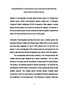
COMPACT ANTENNA ARRAYS FOR MIMO APPLICATIONS Marin Stoytchev(1) +, Hugo Safar(1), Aris L. Moustakas(2), Steve Simon(2) (1) Agere Systems, 700 Mountain Ave, Murray Hill, NJ, USA (2) Lucent Technologies, Bell Laboratories, 700 Mountain Ave, Murray Hill, NJ, USA Abstract: We use antenna-antenna interactions to reduce spatial correlations among antenna elements, which allows for closely packed arrays for MIMO applications in small portable devices. The reduction in spatial correlations is a result of the modification of the antennas’ radiation pattern when the elements are brought close to each other. We show how a particular dielectric antenna element can be manipulated so that closely placed elements have either nearly isotropic radiation patterns or more anisotropic ones. Accordingly, we find that in a multiplescattering environment the correlation between antennas with isotropic pattern has the oscillatory behavior with period ~λexpected for a 3D Rayleigh fading environment. On the other hand, antennas with anisotropic pattern show low degree of spatial correlation of ~ 0.2 independent of the antenna separation. Electromagnetic simulations confirm our experimental observation and provide a path for a systematic design and optimization of compact antenna arrays. Introduction: Multiple-input multiple-output (MIMO) techniques have attracted a great deal of attention with their potential to achieve high data transmission rates. [1] Central to these schemes is the existence of independent spatial channels allowing simultaneous transmission and reception of independent streams of information. Thus, correlation between antennas could be crucial for the performance of the system. In the case of a rich scattering environment (Rayleigh fading), separating the elements in the receive and transmit arrays by at least λ/2 would ensure the required channel independence. While this does not present a problem in a base station, accommodating multiple-antenna arrays in a small portable device with such a separation between antenna elements might not be possible. In this work, we demonstrate that one can use antenna coupling to build compact antenna arrays with very low correlations between different elements, which makes possible the implementation of MIMO techniques in small terminals. By taking advantage of antenna-antenna interactions, we build arrays in which each element’s radiation pattern has lobes of maximum gain oriented towards different regions of the space, thus effectively de-correlating the received signals regardless of the separation among the antenna elements. Antenna elements: We use dielectric antenna elements (product of Toko, Inc. [2]) designed for use in wireless modems for laptop computers (Fig 1a). The manufacturer’s suggested use is mounting the element on a ground plane that is large compared to the size of the antenna. However, since our objective is to study correlations between antennas that are separated by small distances we use two different antenna realization based on the original element that are schematically presented in Fig. 1b,c. In the first case (b), we use a circular ground plate with a radius of ~ λ/4, while in (c) the ground plate is eliminated completely. Measurements of the gain and the radiation patterns show that both antennas are linearly (vertically) polarized and have resonant frequencies at 2.50 and 2.60GHz, respectively.
(b)
(c)
(a) Fig. 1: (a) image of the antennas used; schematic presentation of elements with (b) and without (c) a ground plate.
0-7803-7070-8/01/$10.00 (c)2001 IEEE
Magnitude of field correlation
1.0
(a)
λ
0.8
(b)
0.6
0.4
0.2
0.0 0.0
0.5
1.0
1.5
Separation between points (units of λ)
Fig. 2. (a) Spatial variations of received power; (b) Magnitude of the resulting field correlations Speckle Pattern: The correlation between the signals measured by two adjacent receive antennas is determined by both the propagation environment and the characteristics of the antennas, including radiation patterns, antenna interaction, etc. In order to determine the effects of antennaantenna interaction on the degree of signal correlation we first determine the correlation between fields measured at different points of space by a single antenna. In this experiment we use a single transmit (Tx) and a single receive (Rx) antenna. The transmit antenna radiates a 2.44 GHz CW modulated at ~ 2 kHz. The complex field is measured at the receive antenna by using a standard heterodyne technique. The measurements were performed in a typical laboratory environment, with a separation of about 7 m between the arrays and no direct line-of-sight (LOS) path. Both Tx and Rx are oriented vertically and are positioned ~ 1.5 m above the ground. The receive antenna is mounted on a horizontal translation stage that covers a 50x70 cm2 area, with a very high precision of ~ 0.2 cm. This yields a two dimensional (2D) map of the received field, from which the spatial correlation function can be readily obtained. To avoid changes in the signal due to changes in the scattering environment the measurements were performed at night hours, when the environment is completely static. A 2D plot of the received power obtained from these measurements is shown in Fig. 2a. A similar pattern is obtained for the phase, but is not presented here for sake of space. The plot shows variations of power with features that are roughly on the scale of λ. The continuity of the speckle pattern indicates that the measured field is static. From this field map we calculate the spatial autocorrelation function defined by: C
E
(∆x) =
V i ⋅V Vi
2
* j
⋅ V
2 j
(1 )
where ∆x is the distance between points “i” and “j”, Vi is the voltage measured at point “i” and Vi * denotes its complex conjugate. We note that the signal Vi is, to a very good approximation, proportional to the component of the electric field at position i along the direction of polarization of the antenna. The brackets denote average over the ensemble defined by pairs separated by the same distance (within 0.2 cm, given our experimental resolution). The magnitude of the correlation function with ∆x is shown in Fig. 2b. We note that the correlation function presented here is obtained from measurements in a single location and that the pairs of points of detection do not span all possible orientations, which does not form a complete statistical ensemble. Thus, the result obtained gives only the gross features expected. The oscillatory behavior of the field correlation is clearly seen with a magnitude of the order of unity for closely spaced points and a minimum for ∆x ~ 0.6λ. Antenna-Antenna Interaction and Radiation Patterns: The correlation function presented above would give the correlation between the signals measured by two independent noninteracting antennas. However, the antennas are physical objects and it is to expect that they will
f
q 0
0
-10
-10 300
60
300
60
240
120
-20 -20
-30
Data
-20
-20 240
120
-10
-10 180
180
Simulation
H plane
V plane
(a)
(b)
Fig. 3 (a) Measured (top) and simulated (bottom) radiation patterns; (b) Vertical radiation pattern for isolated elements (black line) and elements separated by λ/5 (red line) affect each other’s radiation patterns, when brought close together. This effect could lead to changes in the correlations between the antennas to a greater or lesser extent. To determine the effects of the presence of a second antenna on the radiation pattern of an antenna close by we have performed both measurements and simulations of the radiation patterns for the two realizations of antennas used. The results for the shorted antenna at its resonance frequency are presented in Fig. 3. The simulations are made with Ansoft HFSS antenna analysis software using the antenna dimensions and the value of the real part of the dielectric constant (εr = 4) as inputs. Data and simulations show quantitatively similar modifications of the radiation pattern of the active antenna compared to its original dipole pattern, when a 50 Ω-loaded second antenna (dummy) is placed close by (the result shown here are for an antenna spacing of λ/5). Fig. 3b shows the horizontal radiation patterns of a single isolated antenna (black line) and in the presence of the dummy (red line). As a result, in the two-antenna array of Fig. 3(b) the horizontal radiation pattern of the antenna on the right has a main lobe directed towards the right and visa-versa for the antenna on the left, thus creating directional diversity. We expect, therefore, that in multiple scattering environments this effect will reduce the correlations between the two antennas. Two-Antenna Correlations: To investigate the effect of the proximity of two antennas on the correlation between the signals received, we have made measurements of the correlation between the fields detected by two antennas as a function of their separation. The measurements were performed in the same location as in the case of the single antenna mapping of the field. For realizing a statistical ensemble the receive antennas were being moved in a random fashion with respect to the walls, while keeping their orientation vertical (the transmit antenna has the same orientation and is kept stationary). The field received by each antenna was measured simultaneously using a standard two-channel receiver. Measurements were performed with antennas with and without ground plates operated at their resonant frequencies, 2.50 GHz and 2.60 GHz respectively. In addition, since antenna impedance and mutual interaction and radiation pattern are frequency dependent, we have also measured the correlations with elements without ground plate operated slightly off resonance, at 2.44 GHz. At this frequency, while the antenna gain is slightly reduced by ~3 dB, we found the most drastic changes of the antenna radiation pattern in the presence of a second antenna. For a given separation between antenna elements we calculate the correlation between the fields measured by each element by using (1), where Vi is now the voltage measured at Rx1 and Vj is the voltage at Rx2. The results are shown in Fig. 4. In the case of elements with a ground plate (a), we obtain correlations close to the function sin(x)/x corresponding to 3D diffusive wave propagation for non-interacting antennas [4]. For elements without ground plate at the resonant frequency (b) we find similar behavior, but with reduced correlation values. Finally, for elements without ground plate at 2.44 GHz (c) small correlation values of approximately 0.2 throughout the entire range of separations are observed.
Correlation Magnitude
1.0
(a) sin(kx)/kx (A) f0 = 2.5 GHz
0.5
0.0 0.0
0.5
1.0
1.5 0.0
0.5
(b)
(c)
(B) f0 = 2.6 GHz Simulation
(B) f0 = 2.5 GHz
1.0
1.5 0.0
0.5
1.0
1.5
Antenna Separation (units of λ)
Fig. 4: Measured correlations for the different antenna realizations: (a) elements with ground plate; (b) elements without ground plate operated at 2.60GHz, also shown is the result from simulations in full green triangles; (c) elements without ground plate operated at 2.44GHz These results are consistent with the measurements and the simulations of the radiation patterns of the antennas in the presence of a second antenna, where we observe a transition from nearly isotropic radiation patterns in case (a) to highly anisotropic ones in case (c). This finding indicates the possibility of using antenna interactions for creating radiation patterns with directional diversity, so that the signals measured remain uncorrelated, even for closely located antennas. This will allow successful implementation of MIMO techniques in small wireless devices. In addition to measuring the correlation functions between two antennas we have also calculated the correlation values for certain antenna separation. From the far-field obtained from the 3D EM simulations as a function of direction E(θ,φ), the antenna correlations can be calculated using: E 1 ( θ, ϕ ) ⋅E 2 ( θ, ϕ ) + d θ d ϕ ∫ 12 C = (2) 2 2 E E 1 ( θ, ϕ ) d θ d ϕ 2 ( θ, ϕ ) d θ d ϕ ∫ ∫ The results from these calculations assuming complete mixing are given in Fig. 4b (full triangles) and show good agreement with the measured values. Thus, we demonstrate a method of simulating the radiation patterns and using these to calculate the correlations between antennas for the design and optimization of compact arrays with reduced spatial correlations. Conclusions: We have performed a complete experimental study of spatial correlations among antenna elements in indoor environments. Single-antenna measurements of the static electric field pattern illustrate the interference produced by multipath propagation and allow us to obtain the spatial correlation function corresponding to non-interacting antennas. Measurements and simulations of the radiation patterns of antennas brought close to each other show that one can create patterns with directional diversity. Direct measurements of the correlation between two receive antenna elements showed that this in turn leads to very small correlations between antenna elements. This makes possible the realization of compact antenna arrays that allow for MIMO implementations in small wireless devices. Moreover, we demonstrate a reliable method of calculating the correlations between antenna elements using far-field radiation patterns obtained from 3D EM simulations that can be used for array optimization in various applications. REFERENCES: [1] G. J. Foschini, M. Gans, “On Limits of Wireless Communications in a Fading Environment when Using Multiple Antennas,” Wireless Personal Communications 6, 311-335 (1998). [2] Antenna specifications can be found at http://www.toko.com/passives/antennas/dac.asp [3] R. G. Vaughan, N. L. Scott, “Closely Spaced Monopoles for Mobile Communications,” Radio Science 28, 1259 (1993). [4] A. L. Moustakas, H. U. Baranger, L. Balents, A. M. Sengupta, and S. H. Simon, “Communication through a Diffusive Medium: Coherence and Capacity,” Science 287, 287-290 (2000).