Abstractâ In this paper, we propose an efficient model order reduction (MOR) algorithm, called MTermMOR, for modeling inter- connect circuits with large ...
Compact Reduced Order Modeling for Multiple-Port Interconnects ∗
Pu Liu∗ , Sheldon X.-D. Tan∗ , Bruce McGaughy† , Lifeng Wu† Department of Electrical Engineering, University of California, Riverside, CA 92521 † Cadence Design Systems Inc., San Jose, CA 95134
Abstract— In this paper, we propose an efficient model order reduction (MOR) algorithm, called MTermMOR, for modeling interconnect circuits with large number of external ports. The proposed method overcomes the difficulty associated with Krylov subspace based projection MOR methods for reducing circuits with many ports. The novelty of the proposed method lies on the fact that we separately compute the poles and residues of each transfer function in the reduced admittance matrices. Specifically we apply traditional subspace projection method for computing poles and use hierarchical symbolic analysis for computing frequency responses of admittances to determine the residues of transfer functions. In this way, we only use necessary poles (smaller number of poles) to archive the same accuracy than subspace projection based methods. Finally convex programming based optimization is used to enforce the passivity of the reduced models. The new method can lead to much smaller reduced models for a given frequency range or much higher accuracy given the same model sizes than subspace projection based methods for multi-port interconnect circuits. Experimental results on several industry interconnect circuits demonstrate the advantage of the proposed method over the subspace projection based methods.
I. I NTRODUCTION Compact modeling of passive RLC interconnect circuits by model order reduction techniques has been intensively studied in the past due to the urgent need to reduce the increasing circuit complexity as technology scales. The most efficient and successful one is based on subspace projection [9], [5], [11], [8], [6], which was pioneered by Asymptotic Waveform Evaluation (AWE) algorithm [9] where explicit moment matching was used to compute dominant poles at low frequency. Later more numerical stable techniques are proposed [5], [11], [8], [6] by using implicit moment matching and congruence transformation. One problem with the existing projection based model order reduction techniques is that they are not efficient to reduce circuits with many ports. This is reflected in several aspects of the existing algorithms like PRIMA [8]. First, the time complexity of PRIMA is proportional to the number of ports of the circuits as moments excited by every port need to be computed and matrix-valued transfer functions are generated. Second, the poles of the reduced models are linearly increasing with the number of ports, which make the reduced models much larger than necessary. The fundamental reason is that all the projection methods are working directly on the moments which contain the information of both poles and residues for the corresponding transfer function. To deal This work is funded by NSF CAREER Award CCF-0448534, UC Micro #05-111 via Cadence Design System Inc.
with more ports, we have more transfer functions and thus more poles and residues to compute. However, poles among different transfer functions are the same for the same circuits as poles are characteristics of a system. But projection based methods can’t take advantage of this as they operate directly on moments. As more residues are computed for more transfer functions, more poles are also generated. However, generating more poles does not always help to improve the accuracy of the reduced models because more block moments are not always matched as the number of poles increases. As a result, projection based methods lead to larger reduced models than necessary when the number of ports are larger. One way to resolve this problem is by means of port reductions. Recent work by Feldmann et al [4] exploited the port dependence to reduce the number of ports under some error metric constraints. This work however is limited to circuits with main similar ports and it can’t be applied to general linear circuits with many independent ports. Another approach which is also amenable for a circuit with multiple ports is the hierarchical model order reduction methods [13], [10]. But hierarchical model order reduction is also numerically unstable except for tree circuits [13]. The improvement version can produce more accurate models at the expense of multi frequency point expansions [10]. In this paper, we proposed a new model order reduction method that overcomes the difficulty associated with subspace projection based MOR methods for reducing circuits with many ports. The basic idea of the proposed method is to separately compute the poles and residues of the transfer functions in the reduced admittance matrices. This can be achieved firstly by applying traditional subspace projection methods to compute the poles and then using hierarchical symbolic analysis for computing frequency responses of admittances to determine the residues of transfer functions. Since the traditional projection based MOR is used only for computing the poles, we only need to compute the poles necessary for the accuracy requirements. To ensure the passivity of the reduced model, a convex programming based optimization is applied finally. Our experimental results show that the new method can lead to much smaller reduced model sizes for a given frequency range or much higher accuracy given the same model sizes than subspace projection based methods. This paper is organized as the follows: Section II reviews the Krylov subspace based projection methods and points out the their weakness for reducing circuit with multiple ports. Section III will present our new model order reduction algorithm called MTermMOR, which consists of three steps. Section IV will present the experimental results, which demonstrates the advantage of the proposed method over the projection methods on several real industry interconnect
II. R EVIEW OF S UBSPACE P ROJECTION BASED MOR M ETHODS In this section, we review the Krylov subspace based projection methods and point out the their weakness for reducing circuit with multiple port. We look at the most representative Krylov subspace method, PRIMA [8]. Without loss of generality, a linear mport electrical circuit can be expressed as C x˙ n = −Gxn + Bum
(1)
T
im = L xn
(2)
where x is the vector of state variables and n is the number of state variables, m is the number of independence sources specified as ports. C, G and B are matrices from stamping of circuit devices and L indicates the output port. Define A = −G−1 C, A ∈ �n×n and R = G−1 B, R = [r0 , r1 , ..., rm ] ∈ �n×m . The y-parameter matrix after Laplace transformation is Y (s) = LT (G + sC)−1 B = LT (In − sA)−1 R where In is the n × n identity matrix. The block moments of Y (s) are defined as the coefficients of Taylor expansion of Y (s) around s = 0: Y (s) = M0 + M1 s + M2 s2 + ...
(3)
where Mi ∈ �m×m and can be computed as Mi = LT Ai R The idea of model order reduction is to find a compact system of a much smaller size than the original system. Krylov subspace based method accomplishes this by projecting the original system on a special subspace which expands the same space as the block moments of the original system. Specifically, the Krylov subspace is defined as Kr(A, R, q)
2
k−1
R, = colsp[R, AR, A R, ..., A k k k A r0 , A r1 , ..., A rl ] k = �q/m�, l = q − km.
(4) (5)
˜ = X T GX G ˜ = XT L L
the reduced system of size q is found as ˜ xn + Bu ˜ m C˜ x ˜˙ n = −G˜ im
˜ T xn =L
−3
1.4
x 10
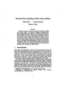
1.2 Original System with 219 nodes MtermMOR model with 9 poles PRIMA model with 9 poles
1
0.8
0.6
0.4
0.2
0 0
1
2
3
4
5
Frequency
For simplicity of expression, we assume q = m × k in the following. In reality any k can be chosen. Then, PRIMA tries to find orthogonal matrix X ∈ �n×q such that colsp(X) = Kr(A, R, q). With C˜ = X T CX ˜ = XT B B
We use the following practical industry interconnect circuit from our industry partner to further illustrate this problem. The circuit has 3 ports and 219 nodes. Fig. 1 shows the frequency response of one of the nine transfer functions. With 3 block moments, PRIMA matches the exact response up to 3GHz fairly well. However, to generate the Krylov subspace in (5), we need 9 columns, which indicates the reduced system size is 9, i.e. it has 9 poles. However with the new method proposed in this paper, we can actually obtain a reduced system of the same size but matches the original system response up to 100GHz and still preserves passivity as PRIMA does. As the number of ports grows, generating a certain number of block moments becomes more and more expensive and the reduce system becomes much larger. However, in real industrial interconnect circuits, subcircuits can easily have ten to hundreds ports, and substrates can even be models with hundreds of ports. For this kind of circuits, the Krylov subspace projection method will be extremely inefficient.
Siemens (mho)
circuits. The conclusion and future works are presented in section V.
(6) (7)
The reduced systems have q poles, which are the dominant poles of the original systems. Notice that the order of block moments k is related to q by k = �q/m�. To match the first block moment (k = 1), we need at least m poles. For every one order of block moment increase, we need to add additional m poles, which leads a highly inefficient reduction process.
6
7
8
9
10 10
x 10
Fig. 1. Frequency response of 3-input circuit.
III. T HE P ROPOSED N EW M ODEL O RDER R EDUCTION M ETHOD : MT ERM MOR In this section, we present the new model reduction algorithm, which is suitable for circuits with multiple ports. The key idea of the proposed method is to compute the poles and residues of the rational admittances (transfer functions) separately. In this way, we can avoid the generation of unnecessary poles as done in the traditional subspace projection methods. The new method consists of three steps to produce compact passive models for passive interconnect circuits. MTermMOR: The New Model Order Reduction 1. Compute the required poles by a subspace projection based method. 2. Compute the frequency responses of all the rational admittances for the desired frequency ranges by symbolic
A. Computation of System Poles By Subspace Projection Methods
eliminate poles that have little impact on the frequency range of our interest. Indeed as shown in Fig. 2, we can use only 4 of the 9 poles in a example circuit and still match the exact response very well. The size of the model system is reduced from 219 to 4 but with very good accuracy as it matches with the original system up to 100GHz. This example shows that there exist great potential to further reduce the model sizes from subspace projection based methods while maintaining the same or better accuracy. −3
1.4
x 10
1.2 Original System with 219 nodes MtermMOR model with 4 poles PRIMA model with 9 poles
1
Siemens (mho)
hierarchical analysis. 3. Apply convex programming based method to find the residues of each rational admittance and ensure the passivity of the reduced admittance matrix. Since the poles and residues are computed separately, we can only generate required poles which have impacts on the interested frequency range. As a result, only a few poles are typically required. In the sequel, we detail each reduction step. We want to stress that the new method is different from the traditional frequency-domain fitting method in that (1) the poles are computed by projection-based methods which are the most accurate methods (versus methods like direct moment matching); (2) exact admittance responses are obtained by hierarchical simulation method which is more efficient than other numerical methods used in SPICE and other simulators (versus measured results and other simulated results); (3) The resulting reduced model is passive.
0.8
0.6
0.4
For our problem in this step, we are only interested in the poles of the circuits. The computation costs is no longer associated with the number of ports as all the transfer functions among different ports share the same set of poles. There are several ways to find the required system poles that are dependent on how the moments are computed in the subspace projection framework. The simplest way is to compute the moments from just one input (any one port) until the sufficient number of moments are obtained. The second method obtains the moments from different inputs. If we use the moments from all the m ports, we obtain the block moments as used in PRIMA. But we may only need a few orders of block moments as the poles generated will be km, where k is the order of block moments for the accuracy requirement. After the q moments are generated either from one input or multiple inputs, the projection method X is generated and the reduced system is obtained by the congruence transformation as shown in Eq.(6) and Eq.(7). The required q poles can be ˜ whose ˜ −1 C, found by the eigen-decomposition on matrix G eigenvalues are reciprocals of the required poles: 1 (8) pi = − λi where pi and λi are the ith pole and eigenvalue. Moreover, by applying the pole selection rule in [10], we actually prune out a great portion of poles that have little impact in the frequency range of interest. Specifically, in contrast to many analog circuits where most poles carefully designed to lie on the real axis, the poles of interconnect circuits are usually complex poles. As shown in [2], poles that dominate the transient response in interconnect circuits are those near the imaginary axis with large residues. And as observed in [10], the frequency range that a pole has a major impact is closely related to its imaginary part: the pole has peak responses at frequency equaling to the value of its imaginary part divided by 2π. With these observations we can
0.2
0 0
1
2
3
4
5
Frequency
6
7
8
9
10 10
x 10
Fig. 2. Frequency response of 3-input circuit.
B. Symbolic Hierarchical Analysis for Admittance Response Once the poles are computed, we need to compute the residues of each rational admittance function. For this propose, we need to know the frequency response of each rational admittance function in the reduced admittance matrix Yk×k (s). This can be computed efficiently by using the symbolic hierarchical analysis [14]. In the following, we briefly review the hierarchical symbolic analysis first. Then we compare it with SPICE for frequency domain admittance response computation. For a given circuit formulated in the modified nodal analysis (MNA) as M X = b. It can also be rewritten in the following form (Schur’s decomposition): ⎤⎡ I ⎤ ⎡ I ⎤ ⎡ x b 0 M II M IB ⎣ M BI M BB M BR ⎦ ⎣ xB ⎦ = ⎣ bB ⎦ . (9) 0 M RB M RR xR bR The matrix, M II , is the internal matrix associated with internal variable vector xI . Hierarchical reduction is to eliminate all the variables in xI , and transform (9) into the following reduced set of equations: � � B � � B∗ � � x b M BB∗ M BR = , (10) M RB M RR xR bR where M BB∗ = M BB − M BI (M II )−1 M IB and bB∗ = bB − M BI (M II )−1 bI . Suppose that the number of internal variables
BB aBB∗ u,v = au,v −
1 det(M II )
m k1 ,k2 =1
II IB aBI u,k1 Δk2 ,k1 ak2 ,v ,
(11)
where u, v = 1, ..., m and bB∗ u
=
bB u
1 − det(M II )
600
500
Hierarchical Symbolic Analysis SPICE
400
Time (sec)
is t, and the number of boundary variables is m. Then each matrix element in M BB∗ and bB∗ can be written in the following expanded forms:
300
m k1 ,k2 =1
II I aBI u,k1 Δk2 ,k1 bk2 ,
(12)
200
where u = 1, ..., m and Δu,v is the first-order cofactor of det(M ) with respect to au,v . Symbolic hierarchical analysis is used to represent all the determinants like det(M II ) and first-order cofactor like IB II I ΔII k2 ,k1 ak2 ,v and Δk2 ,k1 bk2 symbolically using the determinant decision diagram (DDD) based method. It was shown in [14], it is as efficient as the direct solution methods such as LU decomposition methods and scalable to large circuits. For our problem, we need to compute all the rational admittances in the reduced admittance matrix. For m ports system, we have m2 admittance functions to compute. It turns out that there are huge advantages of using symbolic hierarchical method over LU based numerical methods. The reason is that the cost of computing all the rational admittances are almost similar to the cost of computing just one rational admittance due to the symbolic sharing among all the rational admittances. We use the clock net with 219 nodes to illustrate this. Fig. 3 shows the computation costs of the symbolic hierarchical method versus the SPICE on this circuit with different number of ports used. Notice that each entry in the admittance matrix is essentially a transfer function. For example, when computing frequency response of the (1, 2) entry, we need to apply a voltage source at port 1 and observe the current at port 2. A lot of information can be reused in our hierarchical symbolic analysis engine, but SPICE cannot take advantage of this and we need to change the input and output information for each of the admittance matrix entry. As a result the simulation time of SPICE increases linearly with the number of ports as shown in Fig. 3. But for the hierarchical analysis the computational cost increase is much smaller and the difference will become more significant as more ports are used.
C. Residue Computation and Passivity Enforcement Passivity is an important property of many physical systems. Brune [1] has proved that the admittance and impedance matrix of an electrical circuit consisting of an interconnection of a finite number of positive R, positive C, positive L, and transformers are passive if and only if their rational functions are positive real. For a general linear (linearized) time-invariant network, we describe it in state-space equations as follows. x˙ = Ax + Bu y = Cx + Du
(13)
Where x is n-dimensional state vector, u is p-dimensional input vector, and y is q-dimensional output vector. The
100
0 0
5
10
15
Port Num
20
25
30
Fig. 3. Comparison of computation cost for admittance.
transfer function through Laplace transformation is Y (s) = C(sI − A)−1 B + D
(14)
where I denote an identity matrix with the same dimension as state matrix A. In [3] a Positive Real Lemma has been introduced to check passivity of the system. The following two statements can be proved to be equivalent. (a) a transfer function matrix Y (s) is positive real. (b) Let (A B C D) be a state-space representation of Y (s). ∃K, (15) K = K T , K ≥ 0, such that the Linear Matrix Inequality (LMI) � � T A K + KA KB − C T ≥0 B T K − C −D − DT
(16)
holds. If we include the term proportional to s in the transfer function, which means we would like to know what would happen in infinite frequency, we can write the admittance matrix in terms of (A B C D) as Y (s) = sY ∞ + D + C(sI − A)−1 B
(17)
In order to keep the transfer function consistently positive real, the term Y ∞ must satisfy Y ∞ = (Y ∞ )T , Y ∞ ≥ 0
(18)
In summary, the problem of checking whether the admittance matrix Y (s) is positive real is transferred into the problem of checking whether its corresponding state space model in terms of (A B C D Y ∞ ) is positive semi-definite. It turns out that the latter is more easily to check and enforce than the former. After we apply the traditional subspace projection method for pole computation, we can obtain its state-space representation A and B. We assume that all admittance rational functions share the common poles of the system. Then for a
A=
A1,1 . . . 0
··· .. . ···
0 . . .
Am,m
C1,1 . . . Cm,1
··· .. . ···
C1,m . . . Cm,m
B=
B1,1 . . . 0
··· .. . ···
0 . . .
Bm,m
(19) . Where each Ap,p ∈ �n×n and Bp,p ∈ �n×1 . So the state matrix A ∈ �mn×mn and the input matrix B ∈ �mn×m . Correspondingly the residues we want to compute can be formulated as C=
D=
D1,1 . . . Dm,1
··· .. . ···
D1,m . . . Dm,m
(20) Where each Cp,q ∈ �1×n , Dp,q ∈ �1×1 .So the output matrix C ∈ �m×mn and D ∈ �m×m as well as Y ∞ ∈ �m×m . Using hierarchical symbolic analysis, we get the frequency responses of admittances Yˆ (s) with a set of N sampling points. Let Yˆp,q (sk ) be the exact value of the entry (p, q) at the k th frequency point and Y˜p,q (sk ) be the computational value obtained from the optimized C, D, Y ∞ . The optimization problem is to determine C, D, Y ∞ such that a cost function is minimized with constraints on the error (Y˜p,q − Yˆp,q ). Here the constraints are on the weighted least square error, taken over N frequencies N �
We use PRIMA as the Krylov subspace projection method for pole computation implemented in MATLAB. The frequency responses are computed using the symbolic hierarchical analysis tool. Then the convex programming tool, SeDuMi, take in the poles and frequency response information and perform the optimization to produce the final reduced models in s-domain. The first interconnect circuit clktree50, is a clock tree circuit in 160nm technology. This network contains 210 nodes and 9 terminals. In Fig.4, the PRIMA model’s response is accurate at the frequency no more than 15GHz. However the MTermMOR model’s response matches the original circuit up to 50GHz. Moreover the MTermMOR model only contains 5 dominant poles comparing with 90 poles in PRIMA model. −4
14
x 10
Original System MtermMOR model PRIMA model
12
10
Siemens (mho)
multi-variable m-port network, we can write its state-space representation in the controllable form as
8
6
wk,p,q �Y˜p,q (sk ) − Yˆp,q (sk )�22 < tp,q
(21)
k=1
4
For simplicity, you can assume that wp,q,k = 1 for all values of k, p and q. In this paper we choose wp,q,k = 1/�Yˆp,q (sk )� to normalize the relative error. Now we can write the whole convex optimization problem as minimize: subject to:
∞
t(K, C, D, Y ) Eq. (15), (16), (18), (21) ∀1 ≤ p, q ≤ m, tp,q ≤ t, t ≥ 0
2 0
0.5
1
1.5
2
2.5
Frequency
3
3.5
4
4.5
5 10
x 10
Fig. 4. Frequency response comparison among the original circuit, PRIMA model, and MTermMOR model of the circuit clktree50.
(22)
where m is the port number of the circuit. Both the objective function and the constraints are convex functions of variables t, tp,q , K, C, D, and Y ∞ . Since N may be large, Eq.(21) will lead to a very large number of constraints. Thus we use a more compact form [3] in our implementation. IV. E XPERIMENTAL R ESULTS The proposed method has been implemented using C++ and MATLAB. We tested our algorithm on two real industry interconnect circuits from our industry partner. The experimental results are collected on a PC with P-IV 3.0Ghz CPU and 512MB RAM. The convex programming problem is solved by using a standard optimization package, SeDuMi [12] in our passivity enforcement implementation. SeDuMi is powerful software package add-on for MATLAB, which allows you solve optimization problems with linear, quadratic and semi-definite constraints.
The similar results are obtained from another example sram1026, which is one bit line circuit from a SRAM circuit also in 160nm technology. This circuit includes 516 nodes, 6 inputs and 256 outputs. Due to the large number of terminals, the constraints Eq.(21) will be increased quadratically, which will also increase the computational cost to solve the optimization problem Eq.(22). However this problem can be mitigated by using recently introduced terminal reduction technique [7] before we perform the convex program. After the terminal reduction, the 6 input ports are all kept and the output ports are reduced to 5 comparing with the original 256 output terminals. Then the convex programming algorithm can easily handle the terminal reduced circuit, which has only 11 terminals. The experimental result is shown in Fig.5. PRIMA’s model by using 44 poles is accurate up to 2Ghz while the MTermMOR model matches the original circuit’s response up to 10Ghz with just 4 poles. Both examples clearly demonstrate the advantage of the proposed method. We also realize this reduced model into an equivalent SPICE netlist and compare its step response with that of the
−5
3.82
x 10
3.8
external ports. The proposed method overcomes the difficulty associated with subspace projection based MOR methods for reducing circuits with many ports. Our contribution is the new reductions flow which separately computes the poles and residues of each transfer function in the reduced admittance matrices. The new method can lead to much smaller reduced models for a given frequency ranges or much higher accuracy given the same model sizes than subspace projection based methods. To ensure the passivity, the convex programming based optimization is used. The new method is a closed-loop method as it can produce models matching the desired frequency ranges precisely. Experimental results demonstrated the advantage of the proposed method over the subspace projection based methods.
Original System MtermMOR model PRIMA model
Siemens (mho)
3.78
3.76
3.74
3.72
3.7
3.68
3.66 0
1
2
3
4
5
6
7
8
Frequency
9
10 9
x 10
R EFERENCES Fig. 5. Frequency response comparison among the original circuit, PRIMA model, and MTermMOR model of the circuit sram1026.
original circuit in time domain. The result is shown in Fig.6. 1 0.9
Original System MtermMOR model
0.8
Voltage (V)
0.7 0.6 0.5 0.4 0.3 0.2 0.1 0 0
0.2
0.4
0.6
0.8
Time (s)
1 −10
x 10
Fig. 6. Step response comparison among the original circuit and MTermMOR model of the circuit sram1026.
Although the proposed method is very effective for generating compact models, its capacity is limited by the convex programming step if no terminal is reduced. The current computing configurations (512MB memory) allows the optimization for circuits with about 15 ports in the MATLAB computing environment. But as shown in the examples, with terminal reduction technique, we can actually handle circuits with much large terminals. Also more efficient convex programming implementation in [3] can be used to further improve the capacity. V. C ONCLUSION AND F UTURE W ORKS In this paper, we have proposed a new compact reduced modeling technique to reduce interconnect circuits with many
[1] O. Brune, “Synthesis of a finite two-terminal network whose driving point impedance is a prescribed function of frequency,” Journal of Math. and Phys., vol. 10, pp. 191–236, 1931. [2] E. Chiprout and M. S. Nakhla, “Analysis of interconnect networks using complex frequency hopping,” IEEE Trans. on Computer-Aided Design of Integrated Circuits and Systems, vol. CAD-14, no. 2, pp. 186–200, Feb. 1995. [3] C. P. Coelho, J. Phillips, and L. M. Silveira, “A convex programming approach for generating guaranteed passive approximations to tabulated frequency-data,” IEEE Trans. on Computer-Aided Design of Integrated Circuits and Systems, vol. 23, no. 2, pp. 293–301, Feb. 2004. [4] P. Feldmann, “Model order redution techniques for linear systems with large numbers of terminals,” in Proc. European Design and Test Conf. (DATE), 2004, pp. 944–947. [5] P. Feldmann and R. W. Freund, “Efficient linear circuit analysis by pade approximation via the lanczos process,” IEEE Trans. on ComputerAided Design of Integrated Circuits and Systems, vol. 14, no. 5, pp. 639–649, May 1995. [6] R. W. Freund, “SPRIM: structure-preserving reduced-order interconnect macromodeling,” in Proc. Int. Conf. on Computer Aided Design (ICCAD), 2004, pp. 80–87. [7] P. Liu, S. X.-D. Tan, H. Li, Z. Qi, J. Kong, B. McGaughy, and L. He, “An efficient method for terminal reduction of interconnect circuits considering delay variations,” in Proc. Int. Conf. on Computer Aided Design (ICCAD), 2005, pp. 821–826. [8] A. Odabasioglu, M. Celik, and L. Pileggi, “PRIMA: Passive reduced-order interconnect macromodeling algorithm,” IEEE Trans. on Computer-Aided Design of Integrated Circuits and Systems, pp. 645– 654, 1998. [9] L. T. Pillage and R. A. Rohrer, “Asymptotic waveform evaluation for timing analysis,” IEEE Trans. on Computer-Aided Design of Integrated Circuits and Systems, pp. 352–366, April 1990. [10] Z. Qi, S. X.-D. Tan, H. Yu, L. He, and P. Liu, “Wideband modeling of RF/analog circuits via hierarchical multi-point model order reduction,” in Proc. Asia South Pacific Design Automation Conf. (ASPDAC), Jan. 2005, pp. 224–229. [11] M. Silveira, M. Kamon, I. Elfadel, and J. White, “A coordinatetransformed Arnoldi algorithm for generating guaranteed stable reduced-order models of RLC circuits,” in Proc. Int. Conf. on Computer Aided Design (ICCAD), 1996, pp. 288–294. [12] J. Sturm, “Using SuDuMi 1.02, a matlab toolbox for optimization over symmetric cones,” Optim. Meth. Softw., vol. 10, pp. 625–653, 1999. [13] S. X.-D. Tan, “A general s-domain hierarchical network reduction algorithm,” in Proc. Int. Conf. on Computer Aided Design (ICCAD), 2003, pp. 650–657. [14] X.-D. Tan and C.-J. Shi, “Hierarchical symbolic analysis of large analog circuits via determinant decision diagrams,” IEEE Trans. on ComputerAided Design of Integrated Circuits and Systems, vol. 19, no. 4, pp. 401–412, April 2000.