Comparing Hardware Performance of Fourteen Round Two SHA-3 Candidates Using FPGAs
Ekawat Homsirikamol
Marcin Rogawski
Kris Gaj
George Mason University ehomsiri, mrogawsk,
[email protected]
Last revised: December 21, 2010
This work has been supported in part by NIST through the Recovery Act Measurement Science and Engineering Research Grant Program, under contract no. 60NANB10D004.
Contents 1 Introduction and Motivation
2
2 Methodology 2.1 Choice of a Language, FPGA Devices, and Tools 2.2 Performance Metrics for FPGAs . . . . . . . . . 2.3 Uniform Interface . . . . . . . . . . . . . . . . . . 2.4 Assumptions and Simplifications . . . . . . . . . 2.5 Optimization Target . . . . . . . . . . . . . . . . 2.6 Design Methodology . . . . . . . . . . . . . . . .
. . . . . .
. . . . . .
. . . . . .
. . . . . .
. . . . . .
. . . . . .
. . . . . .
. . . . . .
. . . . . .
. . . . . .
. . . . . .
. . . . . .
. . . . . .
4 4 4 7 9 9 10
3 Comprehensive Designs of SHA-3 Candidates 3.1 Notations and Symbols . . . . . . . . . . . . . . . . . . 3.2 Basic Component Description . . . . . . . . . . . . . . 3.2.1 Multiplication by 2 in the Galois Field GF(28 ) 3.2.2 Multiplication by n in the Galois Field GF(28 ) 3.2.3 AES . . . . . . . . . . . . . . . . . . . . . . . . 3.3 BLAKE . . . . . . . . . . . . . . . . . . . . . . . . . . 3.3.1 Block Diagram Description . . . . . . . . . . . 3.3.2 256 vs. 512 Variant Differences . . . . . . . . . 3.4 Blue Midnight Wish (BMW) . . . . . . . . . . . . . . 3.4.1 Block Diagram Description . . . . . . . . . . . 3.4.2 256 vs. 512 Variant Differences . . . . . . . . . 3.5 CubeHash . . . . . . . . . . . . . . . . . . . . . . . . . 3.5.1 Block Diagram Description . . . . . . . . . . . 3.5.2 256 vs. 512 Variant Differences . . . . . . . . . 3.6 ECHO . . . . . . . . . . . . . . . . . . . . . . . . . . . 3.6.1 Block Diagram Description . . . . . . . . . . . 3.6.2 256 vs. 512 Variant Differences . . . . . . . . . 3.7 Fugue . . . . . . . . . . . . . . . . . . . . . . . . . . . 3.7.1 Block Diagram Description . . . . . . . . . . .
. . . . . . . . . . . . . . . . . . .
. . . . . . . . . . . . . . . . . . .
. . . . . . . . . . . . . . . . . . .
. . . . . . . . . . . . . . . . . . .
. . . . . . . . . . . . . . . . . . .
. . . . . . . . . . . . . . . . . . .
. . . . . . . . . . . . . . . . . . .
. . . . . . . . . . . . . . . . . . .
. . . . . . . . . . . . . . . . . . .
. . . . . . . . . . . . . . . . . . .
. . . . . . . . . . . . . . . . . . .
. . . . . . . . . . . . . . . . . . .
13 13 15 15 15 16 19 19 21 24 24 24 26 26 26 29 29 31 33 33
2
. . . . . .
. . . . . .
Comparing Hardware Performance of Fourteen Round Two SHA-3 Candidates
3.8
3.9
3.10
3.11
3.12
3.13
3.14
3.15
3.16
3.17
3.7.2 256 vs. 512 Variant Differences Groestl . . . . . . . . . . . . . . . . . 3.8.1 Block Diagram Description . . 3.8.2 256 vs. 512 Variant Differences Hamsi . . . . . . . . . . . . . . . . . . 3.9.1 Block Diagram Description . . 3.9.2 256 vs. 512 Variant Differences JH . . . . . . . . . . . . . . . . . . . . 3.10.1 Block Diagram Description . . 3.10.2 256 vs. 512 Variant Differences Keccak . . . . . . . . . . . . . . . . . . 3.11.1 Block Diagram Description . . 3.11.2 256 vs. 512 Variant Differences Luffa . . . . . . . . . . . . . . . . . . . 3.12.1 Block Diagram Description . . 3.12.2 256 vs. 512 Variant Differences SHA-2 . . . . . . . . . . . . . . . . . . 3.13.1 Block Diagram Description . . 3.13.2 256 vs. 512 Variant Differences Shabal . . . . . . . . . . . . . . . . . . 3.14.1 Block Diagram Description . . 3.14.2 256 vs 512 Variant Differences SHAvite-3 . . . . . . . . . . . . . . . . 3.15.1 Block Diagram Description . . 3.15.2 256 vs. 512 Variant Differences SIMD . . . . . . . . . . . . . . . . . . 3.16.1 Block Diagram Description . . 3.16.2 256 vs. 512 Variant Differences Skein . . . . . . . . . . . . . . . . . . . 3.17.1 Block Diagram Description . . 3.17.2 256 vs. 512 Variant Differences
. . . . . . . . . . . . . . . . . . . . . . . . . . . . . . .
. . . . . . . . . . . . . . . . . . . . . . . . . . . . . . .
. . . . . . . . . . . . . . . . . . . . . . . . . . . . . . .
. . . . . . . . . . . . . . . . . . . . . . . . . . . . . . .
. . . . . . . . . . . . . . . . . . . . . . . . . . . . . . .
. . . . . . . . . . . . . . . . . . . . . . . . . . . . . . .
. . . . . . . . . . . . . . . . . . . . . . . . . . . . . . .
. . . . . . . . . . . . . . . . . . . . . . . . . . . . . . .
. . . . . . . . . . . . . . . . . . . . . . . . . . . . . . .
. . . . . . . . . . . . . . . . . . . . . . . . . . . . . . .
. . . . . . . . . . . . . . . . . . . . . . . . . . . . . . .
. . . . . . . . . . . . . . . . . . . . . . . . . . . . . . .
. . . . . . . . . . . . . . . . . . . . . . . . . . . . . . .
. . . . . . . . . . . . . . . . . . . . . . . . . . . . . . .
. . . . . . . . . . . . . . . . . . . . . . . . . . . . . . .
. . . . . . . . . . . . . . . . . . . . . . . . . . . . . . .
. . . . . . . . . . . . . . . . . . . . . . . . . . . . . . .
3 . . . . . . . . . . . . . . . . . . . . . . . . . . . . . . .
. . . . . . . . . . . . . . . . . . . . . . . . . . . . . . .
. . . . . . . . . . . . . . . . . . . . . . . . . . . . . . .
. . . . . . . . . . . . . . . . . . . . . . . . . . . . . . .
4 Design Summary and Results 4.1 Design Summary . . . . . . . . . . . . . . . . . . . . . . . . . . . . . . . . . 4.2 Relative Performance of the 512 and 256-bit Variants of the SHA-3 Candidates 4.3 Results . . . . . . . . . . . . . . . . . . . . . . . . . . . . . . . . . . . . . . .
35 39 39 41 43 43 45 48 48 48 53 53 57 58 58 58 65 65 65 67 67 67 69 69 70 75 75 82 86 86 87 90 90 91 93
5 Results from Other Groups 108 5.1 Best Results from Other Groups . . . . . . . . . . . . . . . . . . . . . . . . 108 5.2 Best Results . . . . . . . . . . . . . . . . . . . . . . . . . . . . . . . . . . . . 109
4
E. Homsirikamol, M. Rogawski, and K. Gaj
6 Conclusions and Future Work
114
A Absolute Results for Ten FPGA Families
116
Abstract Performance in hardware has been demonstrated to be an important factor in the evaluation of candidates for cryptographic standards. Up to now, no consensus exists on how such an evaluation should be performed in order to make it fair, transparent, practical, and acceptable for the majority of the cryptographic community. In this report, we formulate a proposal for a fair and comprehensive evaluation methodology, and apply it to the comparison of hardware performance of 14 Round 2 SHA-3 candidates. The most important aspects of our methodology include the definition of clear performance metrics, the development of a uniform and practical interface, generation of multiple sets of results for several representative FPGA families from two major vendors, and the application of a simple procedure to convert multiple sets of results into a single ranking. The VHDL codes for 256 and 512-bit variants of all 14 SHA-3 Round 2 candidates and the old standard SHA-2 have been developed and thoroughly verified. These codes have been then used to evaluate the relative performance of all aforementioned algorithms using ten modern families of Field Programmable Gate Arrays (FPGAs) from two major vendors, Xilinx and Altera. All algorithms have been evaluated using four performance measures: the throughput to area ratio, throughput, area, and the execution time for short messages. Based on these results, the 14 Round 2 SHA-3 candidates have been divided into several groups depending on their overall performance in FPGAs.
Chapter 1
Introduction and Motivation Starting from the Advanced Encryption Standard (AES) contest organized by NIST in 1997-2000 [1], open contests have become a method of choice for selecting cryptographic standards in the U.S. and over the world. The AES contest in the U.S. was followed by the NESSIE competition in Europe [2], CRYPTREC in Japan, and eSTREAM in Europe [3]. Four typical criteria taken into account in the evaluation of candidates are: security, performance in software, performance in hardware, and flexibility. While security is commonly recognized as the most important evaluation criterion, it is also a measure that is most difficult to evaluate and quantify, especially during a relatively short period of time reserved for the majority of contests. A typical outcome is that, after eliminating a fraction of candidates based on security flaws, a significant number of remaining candidates fail to demonstrate any easy to identify security weaknesses, and as a result are judged to have adequate security. Performance in software and hardware are next in line to clearly differentiate among the candidates for a cryptographic standard. Interestingly, the differences among the cryptographic algorithms in terms of hardware performance seem to be particularly large, and often serve as a tiebreaker when other criteria fail to identify a clear winner. For example, in the AES contest, the difference in hardware speed between the two fastest final candidates (Serpent and Rijndael) and the slowest one (Mars) was by a factor of seven [1][4]; in the eSTREAM competition the spread of results among the eight top candidates qualified to the final round was by a factor of 500 in terms of speed (Trivium x64 vs. Pomaranch), and by a factor of 30 in terms of area (Grain v1 vs. Edon80) [5][6]. At this point, the focus of the attention of the entire cryptographic community is on the SHA-3 contest for a new hash function standard, organized by NIST [7][8]. The contest is now in its second round, with 14 candidates remaining in the competition. The evaluation is scheduled to continue until the second quarter of 2012. In spite of the progress made during previous competitions, no clear and commonly 2
Comparing Hardware Performance of Fourteen Round Two SHA-3 Candidates
3
accepted methodology exists for comparing hardware performance of cryptographic algorithms [9]. The majority of the reported evaluations have been performed on an ad-hoc basis, and focused on one particular technology and one particular family of hardware devices. Other pitfalls included the lack of a uniform interface, performance metrics, and optimization criteria. These pitfalls are compounded by different skills of designers, using two different hardware description languages, and no clear way of compressing multiple results to a single ranking. In this paper, we address all the aforementioned issues, and propose a clear, fair, and comprehensive methodology for comparing hardware performance of SHA-3 candidates and any future algorithms competing to become a new cryptographic standard. Our methodology is based on the use of FPGA devices from various vendors. The advantages of using FPGAs for comparison include short development time, wide availability of tools, and a limited number of vendors dominating the market. The hardware evaluation of SHA-3 candidates started shortly after announcing the specifications and reference software implementations of 51 algorithms submitted to the contest [7][8][10]. The majority of initial comparisons were limited to less than five candidates, and their results have been published at [10]. The more comprehensive efforts became feasible only after NISTs announcement of 14 candidates qualified to the second round of the competition in July 2009. Since then, several comprehensive studies have been reported in the Cryptology ePrint Archive [11][12], at the CHES 2010 workshop [13][14], and during the Second SHA-3 Candidate Conference [15][16][17][18]. This report is an extension of our earlier papers presented at CHES 2010 and the SHA-3 Candidate Conference [13][16]. To our best knowledge, this is the first report that presents the detailed block diagrams of all 14 Round 2 SHA-3 Candidates, and a comprehensive set of results covering two major SHA-3 variants (SHA-3-256 and SHA-3-512) implemented using 10 FPGA families from two major vendors, Xilinx and Altera.
Chapter 2
Methodology 2.1
Choice of a Language, FPGA Devices, and Tools
Out of two major hardware description languages used in industry, VHDL and Verilog HDL, we choose VHDL. We believe that either of the two languages is perfectly suited for the implementation and comparison of SHA-3 candidates, as long as all candidates are described in the same language. Using two different languages to describe different candidates may introduce an undesired bias to the evaluation. FPGA devices from two major vendors, Xilinx and Altera, dominate the market with about 90% of the market share. We therefore feel that it is appropriate to focus on FPGA devices from these two companies. In this study, we have chosen to use ten families of FPGA devices from Xilinx and Altera. These families include two major groups, those optimized for minimum cost (Spartan 3 from Xilinx, and Cyclone II, III, and IV from Altera) and those optimized for high performance (Virtex 4, 5, and 6 from Xilinx, and Stratix II, III, and IV from Altera). Within each family, we use devices with the highest speed grade, and the largest number of pins. As CAD tools, we have selected tools developed by FPGA vendors themselves: Xilinx ISE Design Suite v. 12.3 (including Xilinx XST, used for synthesis) and Altera Quartus II v. 10.0 Subscription Edition Software.
2.2
Performance Metrics for FPGAs
Choosing proper performance metrics for the implementation of hash functions (or any other cryptographic transformations) using FPGAs is a non-trivial task, and no clear consensus exists so far on how these metrics should be defined. Below we summarize our proposed approach, which we applied in our study. 4
Comparing Hardware Performance of Fourteen Round Two SHA-3 Candidates
5
Speed. In order to characterize the speed of the hardware implementation of a hash function, we suggest using Throughput, understood as a throughput (number of input bits processed per unit of time) for long messages. To be exact, we define Throughput using the following formula: block size T hroughput = (2.1) T · (HT ime(N + 1) − HT ime(N )) where block size is a message block size, characteristic for each hash function, HT ime(N ) is a total number of clock cycles necessary to hash an N-block message, T is a clock period, different and characteristic for each hardware implementation of a specific hash function. Throughput defined this way is typically independent of N (and thus the size of the message), as in all hash function architectures we investigated so far, the expression HT ime(N + 1) − HT ime(N ) is a constant that corresponds to the number of clock cycles between processing of two subsequent input blocks. The effective throughput for short messages is always smaller, and is expressed by the formula N · block size T hroughputef f = (2.2) T · HT ime(N ) In this paper, we provide the exact formulas for HT ime(N ) for each SHA-3 candidate (see Table 4.2), and values of f = 1/T for each algorithm–FPGA device pair (see Tables 4.8 and 4.9). Therefore, we provide sufficient information to calculate and compare values of the effective throughputs for each specific message size, which may be of interest in a given application. For short messages, it is more important to evaluate the total time required to process a message of a given size (rather than throughput). The size of the message can be chosen depending on the requirements of an application. For example, in the eBASH study of software implementations of hash functions, execution times for all sizes of messages, from 0-bytes (empty message) to 4096 bytes, are reported, and five specific sizes 8, 64, 576, 1536, and 4096 are featured in the tables [19]. The generic formulas we include in this paper (see Table 4.2) allow the calculation of the execution times for any message size. In order to characterize the capability of a given hash function implementation for processing short messages, we present in this study the comparison of execution times for messages ranging in size from 0 to 1000 bits before padding. Resource Utilization/Area. Resource utilization is particularly difficult to compare fairly in FPGAs, and is often a source of various evaluation pitfalls. First, the basic programmable block (such as CLB slice in Xilinx FPGAs) has a different structure and different capabilities for various FPGA families from different vendors. For example, in Virtex 5 and Virtex 6, a CLB slice includes
6
E. Homsirikamol, M. Rogawski, and K. Gaj
four 6-input Look-Up-Tables (LUTs); in Spartan 3 and Virtex 4, a CLB slice includes two 4-input LUTs. In Cyclone II, III, and IV, the basic programmable block is called Logic Element (LE); in Stratix II, III, and IV, the basic programmable component has a different structure and is called ALUT (Adaptive Look-Up Table). Taking this issue into account, we suggest avoiding any comparisons across family lines. Secondly, all modern FPGAs include multiple dedicated resources, which can be used to implement specific functionality. These resources include Block RAMs (BRAMs), multipliers (MULs), and DSP units in Xilinx FPGAs, and memory blocks, multipliers, and DSP units in Altera FPGAs. In order to implement a specific operation, some of these resources may be interchangable, but there is no clear conversion factor to express one resource in terms of the other. Therefore, we suggest in the general case, treating resource utilization as a vector, with coordinates specific to a given FPGA family. For example, Resource U tilizationSpartan3 = (#CLBslices, #BRAM s, #M U Ls)
(2.3)
Resource U tilizationCycloneIII = (#LE, #memory bits, #M U Ls)
(2.4)
Taking into account that vectors cannot be easily compared to each other, we have decided to opt out of using any dedicated resources in the hash function implementations used for our comparison. Thus, all coordinates of our vectors, other than the first one have been forced (by choosing appropriate options of the synthesis and implementation tools) to be zero. This way, our resource utilization (further referred to as Area) is characterized using a single number, specific to the given family of FPGAs, namely the number of CLB slices (#CLBslices) for Xilinx FPGAs, the number of Logic Elements (#LE) for Cyclone families, and the number of Adaptive Look-Up Tables (#ALU T ) in Stratix families. Unfortunately, in four out of ten families, namely Cyclone II, Cyclone III, Cyclone IV, and Stratix II, the complete elimination of the use of memory blocks is very difficult, and might require a substantial redesign of the circuit. This is because these families have no concept of distributed memory, i.e., memory implemented inside of basic configurable building blocks of Altera FPGAs, such as Logic Elements or Adaptive Look-Up Tables. As a result, each time memory is inferred by the VHDL code, this memory is implemented using memory blocks characteristic for a given family (of the size of 4 kbits in Cyclone II, 9 kbits in Cyclone III and IV, and of the sizes of 512 bytes, 4 kbits, or 512 kbits in Stratix II). In our analysis below we neglect these memory requirements, as typically they amount to a relatively small percentage of memory resources available in target FPGAs. The resource utilization vector in FPGAs (or even its simplified one-coordinate form, referred to as Area above) cannot be easily translated to an equivalent area or the number of transistors in ASICs. Any attempts to define a resource utilization unit that would apply to both technologies (such as an equivalent logic gate) have been mostly unsuccessful, and of limited value in practice. The only common denominator is cost, but unfortunately the prices of integrated circuits, and FPGAs in particular, are not commonly available, and are affected by multiple non-technical factors (including the number of units ordered, the relationship between companies, etc.)
Comparing Hardware Performance of Fourteen Round Two SHA-3 Candidates
2.3
7
Uniform Interface
In order to remove any ambiguity in the definition of our hardware cores for SHA-3 candidates, and in order to make our implementations as practical as possible, we have developed an interface shown in Fig. 2.1a, and described below. In a typical scenario, the SHA core is assumed to be surrounded by two standard FIFO modules: Input FIFO and Output FIFO, as shown in Fig. 2.1b. In this configuration, SHA core is an active module, while a surrounding logic (FIFOs) is passive. Passive logic is much easier to implement, and in our case is composed of standard logic components, FIFOs, available in any major library of IP cores. Each FIFO module generates signals empty and full, which indicate that the FIFO is empty and/or full, respectively. Each FIFO accepts control signals write and read, indicating that the FIFO is being written to and/or read from, respectively. The aforementioned assumptions about the use of FIFOs as surrounding modules are very natural and easy to meet. For example, if a SHA core implemented on an FPGA communicates with an outside world using PCI, PCI-X, or PCIe interface, the implementations of these interfaces most likely already include Input and Output FIFOs, which can be directly connected to a SHA core. If a SHA core communicates with another core implemented on the same FPGA, then FIFOs are often used on the boundary between the two cores in order to accommodate for any differences between the rate of generating data by one core and the rate of accepting data by another core. Additionally, the inputs and outputs of our proposed SHA core interface do not need to be necessarily generated/consumed by FIFOs. Any circuit that can support control signals src ready and src read can be used as a source of data. Any circuit that can support control signals dst ready and dst write can be used as a destination for data. The exact format of an input to the SHA core, for the case of pre-padded messages, is shown in Fig. 2.2. Two scenarios of operation are supported. In the first scenario, the message bitlength after padding is known in advance and is smaller than 2w . In this scenario, shown in Fig. 2.2a, the first word of input represents message length after padding, a)
clk
rst
clk
rst
b)
SHA core w
din
dout
src_ready
dst_ready
src_read
dst_write
w
ext_idata w fifoin_full fifoin_write
clk
rst
clk
rst
clk
rst
clk
rst
Input FIFO din
dout
full
empty
write
read
w fifoin_empty fifoin_read
din
dout
src_ready
dst_ready
src_read
dst_write
rst
clk
rst
Output FIFO
SHA core idata
clk
odata w fifoout_full fifoout_write
din
dout
full empty write read
ext_odata w fifoout_empty fifoout_read
Figure 2.1: a) Input/output interface of a SHA core. b) A typical configuration of a SHA core connected to two surrounding FIFOs.
8
E. Homsirikamol, M. Rogawski, and K. Gaj a)
b) w bits
w bits
msg_len | last = 1
seg_0_len | last=0
msg_len_bp seg_0 seg_1_len | last=0 message
seg_1 . . .
seg_n-1_len | last=1 seg_n-1_len_bp seg_n-1
Figure 2.2: Format of input data for two different operation scenarios: a) with message bitlength known in advance, and b) with message bitlength unknown in advance. Notation: msg len – message length after padding, msg len bp – message length before padding, seg i len – segment i length after padding, seg i len bp – segment i length before padding, last – a one-bit flag denoting the last segment of the message (or one-segment message), “|” – bitwise OR.
expressed in bits. This word has the least significant bit, representing a flag called last, set to one. This word is followed by the message length before padding. This value is required by several SHA-3 algorithms using internal counters (such as BLAKE, ECHO, Shavite-3, and Skein), even if padding is done outside of the SHA core. These two control words are followed by all words of the message. The second format, shown in Fig. 2.2b, is used when either message length is not known in advance, or it is greater than 2w . In this case, the message is processed in segments of data denoted as seg 0, seg 1,. . . ,seg n-1. For the ease of processing data by the hash core, the size of the segments, from seg 0 to seg n-2 is required to be always an integer multiple of the block size b, and thus also of the word size w. The least significant bit of the segment length expressed in bits is thus naturally zero, and this bit, treated as a flag called last, can be used to differentiate between the last segment and all previous segments of the message. The last segment before padding can be of arbitrary length < 2w . This segment is processed in the same way as the entire message in scenario a). This way there is no need for any additional signal to distinguish between these two scenarios. Scenario a) is a special case of scenario b). In case the SHA core supports padding, the protocol can be even simpler, as explained in [20]. Please note that scenario b) is very similar to the way data is processed by a typical software API for hash functions, such as [21]. The Update function of the software API corresponds to processing segments from seg 0 to seg n-2. The function Final corresponds to the processing of the last segment of data, seg n-1.
Comparing Hardware Performance of Fourteen Round Two SHA-3 Candidates
2.4
9
Assumptions and Simplifications
Our study is performed using the following assumptions. Only the SHA-3 candidate variants with the 256-bit and the 512-bit outputs have been implemented and compared at this point. Other variants, treated either independently or as combinations of multiple variants (all-in-one hash cores) may be subjects of future comparisons. Padding is assumed to be done outside of the hash cores (e.g., in software). All investigated hash functions have very similar padding schemes, which would lead to similar absolute area overhead if implemented as a part of the hardware core. The relative area penalty will be higher for cores with smaller area used for main processing. The complexity of the padding circuit will also depend on the assumptions regarding the smallest unit of a message (bit, byte, or word), which may be different for specific applications. Only the primary mode of operation is supported for all functions. Special modes, such as tree hashing or MAC mode are not implemented (their implementation would actually work against the respective candidates, because of the area and speed penalty introduced by these extra features). There is also no support for providing salt specific to each message. The salt values are fixed to all zeros in all SHA-3 candidates supporting this special input (namely BLAKE, ECHO, SHAvite-3, and Skein).
2.5
Optimization Target
We believe that the choice of the primary optimization target is one of the most important decisions that needs to be made before the start of the comparison. The optimization target should drive the design process of every SHA-3 candidate, and it should also be used as a primary factor in ranking the obtained SHA-3 cores. The most common choices are: Maximum Throughput, Minimum Latency, Minimum Area, Throughput to Area Ratio, Product of Latency times Area, etc. Our choice is the Throughput to Area Ratio, where Throughput is defined as Throughput for long messages, and Area is expressed in terms of the number of basic programmable logic blocks specific to a given FPGA family. This choice has multiple advantages. First, it is practical, as hardware cores are typically applied in situations, where the size of the processed data is significant and the speed of processing is essential. Otherwise, the input/output latency overhead associated with using a hardware accelerator dominates the total processing time, and the cost of using dedicated hardware (FPGA) is not justified. Optimizing for the best ratio provides a good balance between the speed and the cost of the solution. Secondly, this optimization criterion is a very reliable guide throughout the entire design process. At every junction where the decisions must be made, starting from the choice of a high-level hardware architecture down to the choice of the particular FPGA tool options, this criterion facilitates the decision process, leaving very few possible paths for further investigation.
10
E. Homsirikamol, M. Rogawski, and K. Gaj
On the contrary, optimizing for Throughput alone, leads to highly unrolled hash function architectures, in which a relatively minor improvement in speed is associated with a major increase in the circuit area. In hash function cores, latency, defined as a delay between providing an input and obtaining the corresponding output, is a function of the input size. Since various sizes may be most common in specific applications, this parameter is not a well-defined optimization target. Finally, optimizing for area leads to highly sequential designs, resembling small general-purpose microprocessors, and the final product depends highly on the maximum amount of area (e.g., a particular FPGA device) assumed to be available.
2.6
Design Methodology
Our design of all 14 SHA-3 candidates followed an identical design methodology. Each SHA core is composed of the Datapath and the Controller. The Controller is implemented using three main Finite State Machines, working in parallel, and responsible for the Input, Main Processing, and the Output, respectively. As a result, each circuit can simultaneously perform the following three tasks: output hash value for the previous message, process a current block of data, and read the next block of data. The parameters of the interface are selected in such a way that the time necessary to process one block of data is always larger or equal to the time necessary to read the next block of data. This way, the processing of long streams of data can happen at full speed, without any visible input interface overhead. The finite state machines responsible for input and output are almost identical for all hash function candidates; the third state machine, responsible for main data processing, is based on a similar template. The similarity of all designs and reuse of common building blocks assures a high fairness of the comparison. The design of the Datapath starts from the high level architecture. At this point, the most complex task that can be executed in an iterative fashion, with the minimum overhead associated with multiplexing inputs specific to a given iteration round, is identified. The proper choice of such a task is very important, as it determines both the number of clock cycles per block of the message and the circuit critical path (minimum clock period). It should be stressed that the choice of the most complex task that can be executed in an iterative fashion should not follow blindly the specification of a function. In particular, quite often one round (or one step) from the description of the algorithm is not the most suitable component to be iterated in hardware. Either multiple rounds (steps) or fractions thereof may be more appropriate. In Table 2.1 we summarize our choices of the main iterative tasks of SHA-3 candidates. Each such task is implemented as combinational logic, surrounded by registers. The next step is an efficient implementation of each combinational block within the DataPath. In Table 2.2, we summarize major operations of all SHA-3 candidates that require logic resources in hardware implementations. Fixed shifts, fixed rotations, and
Comparing Hardware Performance of Fourteen Round Two SHA-3 Candidates
11
Table 2.1: Main iterative tasks of the hardware architectures of SHA-3 candidates optimized for the maximum Throughput to Area ratio Function BLAKE BMW CubeHash ECHO Fugue Groestl
Main Iterative Task Gi ..Gi+3 entire function one round AES round/AES round/ BIG.SHIFTROWS, BIG.MIXCOLUMNS 2 subrounds (ROR3, CMIX, SMIX) Modified AES round
Hamsi
Truncated Non-Linear Permutation P
Function JH Keccak Luffa Shabal SHAvite-3 SIMD Skein
Main Iterative Task Round function R8 Round R The Step Function, Step Two iterations of the main loop AES round 4 steps of the compression function 4 rounds of Threefish-512
Table 2.2: Major operations of SHA-3 candidates (other than permutations, fixed shifts and fixed rotations). mADDn denotes a multioperand addition with n operands. Function
NTT
BLAKE BMW CubeHash ECHO Fugue Groestl Hamsi
S-box
GF MUL
MUL
mADD mADD3 mADD17
LC
JH Keccak Luffa Shabal SHAvite-3 SIMD Skein SHA-256
Linear code
AES 8x8 AES 8x8 AES 8x8 Serpent 4x4 4x4
x02, x03 x04..x07 x02..x05, 0x07
4x4
x02
AES 8x8
x02, x03
x2, x5
Boolean XOR XOR XOR XOR XOR XOR XOR XOR
x3, x5 NTT
ADD /SUB ADD ADD,SUB ADD
x185, x233
ADD,SUB mADD3 mADD5
ADD ADD
NOT,AND,XOR XOR NOT,AND,XOR NOT,XOR NOT,AND,OR XOR NOT,AND,XOR
12
E. Homsirikamol, M. Rogawski, and K. Gaj
other more complex permutations are omitted because they appear in all candidates and require only routing resources (programmable interconnects). The most complex out of logic operations are the Number Theoretic Transform (NTT) [22] in SIMD, linear code (LC) [23] in Hamsi, basic operations of AES (8x8 AES S-box and multiplication by a constant in the Galois Field GF(28 )) in ECHO, Fugue, Groestl, and SHAvite-3; and multioperand additions in BLAKE, BMW, SIMD, and SHA-256. For each of these operations we have implemented at least two alternative architectures. NTT was optimized by using a Fast Fourier Transform (FFT) [22]. In Hamsi, the linear code was implemented using both logic (matrix by vector multiplications in GF(4)), and using look-up tables. AES 8x8 S-boxes (SubBytes) were implemented using both look-up tables (stored in distributed memories), and using logic only (following method described in [24], Section 10.6.1.3). Multi-operand additions were implemented using the following four methods: carry save adders (CSA), tree of two operand adders, parallel counter, and a “+” in VHDL [25]). Finally, integer multiplications by 3 and 5 in Shabal have been replaced by a fixed shift and addition. All optimized implementations of basic operations have been applied uniformly to all SHA-3 candidates. In case the initial testing did not provide a strong indication of superiority of one of the alternative methods, the entire hash function unit was implemented using two alternative versions of the basic operation code, and the results for a version with the better throughput to area ratio have been listed in the result tables. All VHDL codes have been thoroughly verified using a universal testbench, capable of testing an arbitrary hash function core that follows interface described in Section 2.3 [26]. A special padding script was developed in Perl in order to pad messages included in the Known Answer Test (KAT) files distributed as a part of each candidates submission package. An output from the script follows a similar format as its input, but includes apart from padding bits also the lengths of the message segments, defined in Section 2.3, and shown schematically in Fig. 2.2b. The generation of a large number of results was facilitated by an open source tool ATHENa (Automated Tool for Hardware EvaluatioN) [26]. This benchmarking environment was also used to optimize requested synthesis and implementation frequencies and other tool options.
Chapter 3
Comprehensive Designs of SHA-3 Candidates The designs of all 14 SHA-3 candidates followed the same basic design principle with the core separated into two main units, the Datapath and the Controller. Only the Datapath diagrams are provided in this chapter as the Controller can be derived from the Datapath and the specification of the function, and described using ASM charts. The full specification of each of the algorithms can be found in [27–41].
3.1
Notations and Symbols
Table 3.1 provides the notation and symbols that are being used throughout this chapter.
13
14
E. Homsirikamol, M. Rogawski, and K. Gaj
Table 3.1: Notations and Symbols
Word Block X[i] Xi salt b h w IV SEXT ZEXT R
S ||
A group of bits used in arithmetic and logic operations, typically of the size of 32 or 64 bits. A group of words. Refers to an array position i in X. Refers to a bit position i in X. Salt values are always assumed to be zero and as a result they are omitted from the diagrams. Block size in bits. Hash value size in bits. Word size in bits. Initialization vector Sign extension. Zero extension. Rotation left by R positions. If R is a constant: fixed rotation; if R is a variable: variable rotation implemented using a barrel rotator. Rotation right by R positions. If R is a constant: fixed rotation; if R is a variable: variable rotation implemented using a barrel rotator. Shift left by S positions. If S is a constant: fixed shift; if S is a variable: variable shift implemented using a barrel shifter. Shift right by S positions. If S is a constant: fixed shift; if S is a variable: variable shift implemented using a barrel shifter. Concatenation. By default, the buses concatenate back to the same arrangement as before the separation (split) occurs.
SIPO Serial-in-parallel-out unit.
PISO Parallel-in-serial-out unit. switch endian word switch endian byte
Wordwise endianness switching. Bytewise endianness switching.
Comparing Hardware Performance of Fourteen Round Two SHA-3 Candidates
3.2
15
Basic Component Description
This section describes implementations of selected basic components used in more than one algorithm. These components include multiplication by 2 in GF(28 ), SubBytes, MixColumns, and AES Round.
3.2.1
Multiplication by 2 in the Galois Field GF(28 ) X[7] X[6]
Y[7]
X[5]
Y[6]
X[4]
Y[5]
X[3]
Y[4]
X[2]
Y[3] Y[2]
X[1]
Y[1] Y[0]
X[0]
Figure 3.1: Basic : x2
3.2.2
Multiplication by n in the Galois Field GF(28 )
Galois Field multiplication by n other than 2 is summarized in Table 3.2. Table 3.2: Galois Field Multiplication by n x3(X) = x2(X) ⊕ X x4(X) = x2(x2(X)) x5(X) = x4(X) ⊕ X x6(X) = x4(X) ⊕ x2(X) x7(X) = x4(X) ⊕ x3(X)
16
3.2.3
E. Homsirikamol, M. Rogawski, and K. Gaj
AES
AES is a basic building block of many SHA-3 candidates. An AES round consists of three basic operations, SubBytes, ShiftRows, and MixColumns as shown in Figure 3.2. The SubBytes operation, shown in Figure 3.3, performs direct substitution on all bytes of its input. MixColumns performs multiplication of a constant 4x4 matrix by each word of its input. A word of AES contains 32 bits or 4 bytes. Hence, four instances of MC (MixColumn) are required to process the entire AES block of 128 bits, as shown in Figure 3.4 . The SBOX and ShiftBytes operations of AES and their full specifications can be found in [42] and [43]. x 128
SubBytes ShiftRows MixColumns 128 128
key
128
y
Figure 3.2: Basic : AES Round
Comparing Hardware Performance of Fourteen Round Two SHA-3 Candidates
x 128
8
8
8
x[0]
8
x[15]
AES SBOX 8
AES SBOX 8
8
y[0]
8
y[15] 128
y
Figure 3.3: Basic : AES SubBytes
17
18
E. Homsirikamol, M. Rogawski, and K. Gaj
x
a)
128
x[0]
x[1]
x[2]
x[3]
32
32
32
MC
MC
MC
32
32
32
32
y[2]
y[3]
y[0]
y[1]
32
MC
128
y
b)
Note : All buses are 8−bit wide b0
b1
b2
b3
x2
x2
x2
x2
b0’
b0’
b2’
b3’
Figure 3.4: Basic : AES MixColumns. a) Applying MixColumns to the entire AES block, and b) MC: Applying MixColumns to a single word.
Comparing Hardware Performance of Fourteen Round Two SHA-3 Candidates
3.3 3.3.1
19
BLAKE Block Diagram Description
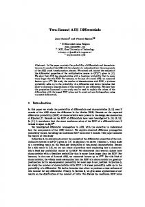
Figure 3.5 shows the datapath of BLAKE. In this design, the combinational CORE implements one half of the BLAKE’s round [27]. Thus, two clock cycles are necessary to implement the full round. First, a message block is loaded into SIPO. Once done, the block is stored in a temporary register, used to hold the message block until this block is fully processed by the CORE. This temporary register allows the next message block to be loaded simultaneously into SIPO. The message block msg and the constant c are then applied as inputs to the function PERMUTE and the obtained output is passed to the design’s CORE. Simultaneously, the chaining value, CV, is initialized with the the Initialization Vector, IV , and an input to the CORE, V , is initialized with the value dependent on the chaining value, the counter, t, and a lower half of the constant c. The initial value of V is mixed by the CORE with an output of the block PERMUTE, CM , for twenty clock cycles (10 rounds). Once this operation is completed, an additional clock cycle is required for finalization. The output of Finalization is used as the next chaining value, for intermediate message blocks, or as the final hash value for the last message block. The Initialization unit performs the following function: h[0] h[1] h[2] h[3] v[0] v[1] v[2] v[3] v[4] v[5] v[6] v[7] h[5] h[6] h[7] . ←− h[4] c[0] v[8] v[9] v[10] v[11] c[1] c[2] c[3] t[0] ⊕ c[4] t[1] ⊕ c[5] c[6] c[7] v[12] v[13] v[14] v[15] The Finalization unit performs the following operation: h0 [0] ← h[0] ⊕ v[0] ⊕ v[8] h0 [1] ← h[1] ⊕ v[1] ⊕ v[9] h0 [2] ← h[2] ⊕ v[2] ⊕ v[10] h0 [3] ← h[3] ⊕ v[3] ⊕ v[11] h0 [4] ← h[4] ⊕ v[4] ⊕ v[12] h0 [5] ← h[5] ⊕ v[5] ⊕ v[13] h0 [6] ← h[6] ⊕ v[6] ⊕ v[14] h0 [7] ← h[7] ⊕ v[7] ⊕ v[15]. In Figure 3.6, an operation of the BLAKE’s PERMUTE module is presented. A new value of the variable m is selected depending on the round number using a wide multiplexer preceded by constant permutations. A permutation table is shown in Table 3.3. The selection signal of the multiplexer cycles from 0 to 19 (and then again back to 0 for BLAKE64) until all BLAKE’s rounds are executed. Each output of the multiplexer is then mixed with the respective constant using the transformation XOR W CROSS (defined in the note to Fig. 3.6) and registered afterwards.
20
E. Homsirikamol, M. Rogawski, and K. Gaj IV
BLAKE−32 : b=512, h=256 BLAKE−64 : b=1024, h=512
b/2
b/2
1
0 b/2 b/2
c
b/2
b/8
t c[0..7]
din
t
h
Initialization
b/2
c
v
CV 64 b
b b/2
SIPO
1
0
b
b
b/2 b msg
b
b
constant
V
V b/2
b/2
CM
CM
PERMUTE
CORE VP b
b v
Finalization h’
h b/2
b/2 b/2
PISO 64
dout Figure 3.5: BLAKE : Datapath
Comparing Hardware Performance of Fourteen Round Two SHA-3 Candidates
21
Table 3.3: BLAKE : Permutation Constants
hi σ0 σ1 σ2 σ3 σ4 σ5 σ6 σ7 σ8 σ9
0 14 11 7 9 2 12 13 6 10
1 10 8 9 0 12 5 11 15 2
2 4 12 3 5 6 1 7 14 8
3 8 0 1 7 10 15 14 9 4
4 9 5 13 2 0 14 12 11 7
5 15 2 12 4 11 13 1 3 6
6 13 15 11 10 8 4 3 0 1
7 6 13 14 15 3 10 9 8 5
8 1 10 2 14 4 0 5 12 15
9 12 14 6 1 13 7 0 2 11
10 0 3 5 11 7 6 15 13 9
low 11 12 2 11 6 7 10 4 12 6 5 15 3 9 4 8 7 1 14 3
13 7 1 0 8 14 2 6 4 12
14 5 9 15 3 1 8 2 10 13
15 3 4 8 13 9 11 10 5 0
The CORE unit is shown in Figure 3.7 and represents one half of the BLAKE’s round. As specified in [27], there are two levels of G functions and therefore a permutation between the first and the second half-round is required. This permutation is performed wordwise and is shown in Table 3.4. LVL2 transforms the state matrix (output of 4 parallel G functions) into a new matrix appropriate for the second half-round. LVL1 is a permutation inverse to LVL2.
input output
input output
0 0
Table 3.4: Blake : Half Round Permutations LVL2 (forward) 1 2 3 4 5 6 7 8 9 10 11 12 1 2 3 5 6 7 4 10 11 8 9 15
13 12
14 13
15 14
0 0
LVL1 (inverse) 5 6 7 8 9 4 5 6 10 11
13 14
14 15
15 12
1 1
2 2
3 3
4 7
10 8
11 9
12 13
The G-function in the CORE unit is shown in Figure 3.8. Note that the XOR operations used to calculate input values CM2i and CM2i+1 , which are normally depicted as a part of the G-function, are omitted in our design. These operations were placed as a part of the PERMUTE unit and therefore skipped here. R1, R2, R3 and R4 are rotating constants. The values of these constants are shown in Table 3.5
3.3.2
256 vs. 512 Variant Differences
BLAKE-64 doubles the word size of BLAKE-32, thereby increasing the block size as well. Hence, the IV and the constant are changed from 512 bits to 1024 bits. These values can
22
E. Homsirikamol, M. Rogawski, and K. Gaj
msg
constant
BLAKE−32 : b=512,w=32 BLAKE−64 : b=1024,w=64
b
small_permute b b
b
P σ 0 hi
b
b
P σ 1 hi
0
i
P σ 8low P σ 9 low
b/2
1
b
Pσ9hi
P σ 0 low b/2
b
b/2
b/2
2
17
b/2
18
19
small_permute 5
b/2
i 5
b/2
b/2
m Note: hi and low denotes top and bottom half of the permutation table m = m[0..7] cm2i = m 2i cm2i+1= m 2i+1
c = c[0..7] c2i+1
XOR_W CROSS
c
b/2
CM
c2i Figure 3.6: BLAKE : PERMUTE Table 3.5: BLAKE : Rotation Constants of BLAKE-32 R1 R2 R3 R4 16 12 8 7
be found in Section 2.2.1 of [27]. BLAKE-64 introduces also an increase in the number of mixing rounds from 10 to 14. As a result, the number of clock cycles required in our design for processing a single block of message increases from 21 to 29. The multiplexer selection signal in the PERMUTE unit loops back when the round number reaches 10. Hence, after reaching 19, this selection signal goes back to 0. Finally, the rotation constants are adjusted to reflect the increased word size. These values are described in Table 3.6.
Comparing Hardware Performance of Fourteen Round Two SHA-3 Candidates
V[0] V[8] V[4] V[12] w A
CM[0,1]
2w
cm
w B
w C
V[1] V[9] V[5] V[13]
w
w
D
w
A
G_function
CM[2,3]
cm
2w
B
w C
V[2] V[10] V[6] V[14]
w
w
D
A
G_function
F
w
CM[4,5]
B
F
b/4
V[3] V[11] V[7] V[15]
w
C
w
D
G_function
cm
2w
w
23
A
CM[6,7]
2w
B
w C
w D
G_function
cm
F
b/4
w
F
b/4
b/4
b
BLAKE−32 : b=512, w=32 BLAKE−64 : b=1024, w=64 w=b/16
LVL2 permute
LVL1 permute
b
b
0
1 b
vp
Figure 3.7: BLAKE : CORE CM2i
CM2i+1
w
A
w
BLAKE−32 : w=32 BLAKE−64 : w=64
w
w
w
w
w
w
w
w
w
w
w