Testing Software and Systems (ICTSS) is the merge of two traditional and impor- tant events which have ... Ana Cristina de Melo (University of Sao Paulo, Brazil).
CRIM ― Documentation/Communications
Proceedings of the 22nd IFIP International Conference on Testing Software and Systems: Short Papers
Editors Alexandre Petrenko Adenilso Simão José Carlos Maldonado October, 2010 ISBN-13: 978-2-89522-136-4 Financial Partner:
Preface
Testing has steadily become more and more important within the development of various software and systems, motivating an increasing amount of research, trying to solve both new challenges imposed by the advancement in other areas of computer science and long-standing problems. Testing has evolved during the last decades from an ad-hoc and under-exposed area of systems development to an important and active research area. The 22nd International Conference on Testing Software and Systems (ICTSS) is the merge of two traditional and important events which have served the testing community as an important venue for discussing advancements in the area. Those events, namely, TestCom the IFIP TC6/WG6.1 International Conference on Testing of Communicating Systems, and Fates International Workshop on Formal Approaches to Testing of Software, together form a large event on testing, validation, and specification of software and systems. They have a long history. TestCom Testing of Communicating Systems is an IFIP-sponsored series of international conferences, previously also called International Workshop on Protocol Test Systems (IWPTS) or International Workshop on Testing of Communicating Systems (IWTCS). It is devoted to testing of communicating systems, including testing of communication protocols, services, distributed platforms, and middleware. The previous events were held in Vancouver, Canada (1988); Berlin, Germany (1989); McLean, USA (1990); Leidschendam, The Netherlands (1991); Montreal, Canada (1992); Pau, France (1993); Tokyo, Japan (1994); Evry, France (1995); Darmstadt, Germany (1996); Cheju Island, South Korea (1997); Tomsk, Russia (1998); Budapest, Hungary (1999); Ottawa, Canada (2000); Berlin, Germany (2002); Sophia Antipolis, France (2003); Oxford, UK (2004); Montreal, Canada (2005); and New York, USA (2006). Fates Formal Approaches to Testing of Software is a series of workshops devoted to the use of formal methods in software testing. Previous events were held in Aalborg, Denmark (2001); Brno, Czech Republic (2002); Montreal, Canada (2003); Linz, Austria (2004); Edinburgh, UK (2005); and Seattle, USA (2006). From 2007 on, TestCom and Fates have been jointly held in Tallinn, Estonia (2007), Tokyo, Japan (2008) and Eindhoven, The Netherlands (2009). The objective of ICTSS 2010 was to be a forum for researchers from academia as well as industry, developers, and testers to present, discuss, and learn about new approaches, theories, methods and tools in the field of testing software and systems. The accepted full papers of the conference were published by Springer as the LNCS volume 6435 ”Testing Software and Systems”. These proceedings contain accepted short papers of ICTSS 2010. It is published by CRIM, Canada, which is one of the organizers of this conference. October 2010
Alexandre Petrenko Adenilso Simao Jose Carlos Maldonado
Conference Organization Program Chairs Alexandre Petrenko (CRIM, Canada) Adenilso Simao (University of Sao Paulo, Brazil) Jose Carlos Maldonado (University of Sao Paulo, Brazil)
Steering Committee Paul Baker (Motorola, UK) Ana R. Cavalli (Telecom SudParis, France) John Derrick (University of Sheffield, UK) (Chair) Wolfgang Grieskamp (Microsoft Research, USA) Roland Groz (Grenoble Institute of Technology, France) Toru Hasegawa (KDDI R&D Labs., Japan) Manuel Nunez (University Complutense de Madrid, Spain) Alexandre Petrenko (CRIM, Canada) Jan Tretmans (Embedded Systems Institute, The Netherlands) Andreas Ulrich (Siemens AG, Germany) Margus Veanes (Microsoft Research, USA)
Program Committee Paul Baker (Motorola, UK) Antonia Bertolino (ISTI-CNR, Italy) Roberto S. Bigonha (Federal University of Minas Gerais, Brazil) Gregor v. Bochmann (University of Ottawa, Canada) Ana R. Cavalli (Telecom SudParis, France) John Derrick (University of Sheffield, UK) Sarolta Dibuz (Ericsson, Hungary) Khaled El-Fakih (American University of Sharjah, UAE) Gordon Fraser (Saarland University, Germany) Wolfgang Grieskamp (Microsoft Research, USA) Roland Groz (Grenoble Institute of Technology, France) Toru Hasegawa (KDDI R&D Labs., Japan) Klaus Havelund (Jet Propulsion Laboratory, USA) Rob Hierons (Brunel University, UK) Teruo Higashino (Osaka University, Japan) Dieter Hogrefe (University of Gottingen, Germany) Antti Huima (Conformiq Inc., USA) Thierry Jeron (IRISA Rennes, France) Ferhat Khendek (Concordia University, Canada) Myungchul Kim (ICU, Korea) Hartmut Konig (BTU Cottbus, Germany)
Victor V. Kuliamin (ISP RAS, Russia) David Lee (Ohio State University, USA) Bruno Legeard (Smartesting, France) Patricia Machado (Federal University of Campina Grande, Brazil) Giulio Maggiore (Telecom Italia Mobile, Italy) Jose Carlos Maldonado (University of Sao Paulo, Brazil) Eliane Martins (University of Campinas, Brazil) Ana Cristina de Melo (University of Sao Paulo, Brazil) Brian Nielsen (University of Aalborg, Denmark) Daltro Jose Nunes (Federal University of Rio Grande do Sul, Brazil) Doron Peled (University of Bar-Ilan, Israel) Alexandre Petrenko (CRIM, Canada) S Ramesh (General Motors India Science Lab, India) Augusto Sampaio (Federal University of Pernambuco, Brazil) Ina Schieferdecker (Fraunhofer FOKUS, Germany) Adenilso Simao (University of Sao Paulo, Brazil) Kenji Suzuki (University of Electro-Communications, Japan) Jan Tretmans (Embedded Systems Institute, The Netherlands) Andreas Ulrich (Siemens AG, Germany) Hasan Ural (University of Ottawa, Canada) M. Umit Uyar (City University of New York, USA) Margus Veanes (Microsoft Research, USA) Cesar Viho (IRISA Rennes, France) Carsten Weise (RWTH Aachen, Germany) Burkhart Wolff (University of Paris-Sud, France) Nina Yevtushenko (Tomsk State University, Russia) Xia Yin (Tsinghua University, China)
Local Chair Marcel Oliveira (Federal University of Rio Grande do Norte, Brazil)
Local Organization Thais Batista (Federal University of Rio Grande do Norte, Brazil) David Deharbe (Federal University of Rio Grande do Norte, Brazil)
Table of Contents
Formal Conformance Verification I. Burdonov and A. Kosachev . . . . . . . . . . . . . . . . . . . . . . . . . . . . . . .
1
Composability Test of BOM based models using Petri Nets I. Mahmood, R. Ayani, V. Vlassov and F. Moradi . . . . . . . . . .
7
Test Suite Reduction in Good Order: Comparing Heuristics from a New Viewpoint A. Bertolino, E. Cartaxo, P. Machado, E. Marchetti and J. Ouriques . . . . . . . . . . . . . . . . . . . . . . . . . . . . . . . . . . . . . . . . . . . . . . . . . .
13
A Multi-objective Tabu Search Algorithm for Reducing Mutation Test Costs ´ A. Banzi, G. Pinheiro, J. Arias, T. Nobre, A. Pozo and S. Vergilio . . . . . . . . . . . . . . . . . . . . . . . . . . . . . . . . . . . . . . . . . . . . . . . . . . . . . .
19
Automatic Test Generation for Data-Flow Reactive Systems with time constraints O. L. N. Timo, H. Marchand and A. Rollet . . . . . . . . . . . . . . . . .
25
Testing Continuous Systems Conformance Using Cross Correlation J. Palczynski, C. Weise and S. Kowalewski . . . . . . . . . . . . . . . . . .
31
Automating Test Case Execution for Real-Time Embedded Systems A. Q. Macedo, W. L. Andrade, D. Rodrigues and P. Machado . . . . . . . . . . . . . . . . . . . . . . . . . . . . . . . . . . . . . . . . . . . . . . . . . . . .
37
A Code Based Approach to Generate Functional Test Scenarios for Testing of Re-hosted Applications N. S. Dsouza, A. Pasala, A. Rickett and O. Estrada . . . . . . . .
43
A Tool for Automatic Generation of Executable Code from Testing Models C. Pons and F. Palacios . . . . . . . . . . . . . . . . . . . . . . . . . . . . . . . . . . . . .
49
Generating Test Cases From B Specifications: An Industrial Case Study A. Moreira, E. Matos, F. Souza and R. Coelho . . . . . . . . . . . . .
55
Approach for a Real-Time Hardware-in-the-Loop System Based on a Variable Step-Size Simulation D. Ulmer and S. Wittel . . . . . . . . . . . . . . . . . . . . . . . . . . . . . . . . . . . . .
61
Automated GUI Testing on the Android Platform M. Kropp and P. Morales . . . . . . . . . . . . . . . . . . . . . . . . . . . . . . . . . . .
67
Automating Inspection of Design Models Guided by Test Cases A. Rocha, P. Machado and F. Ramalho . . . . . . . . . . . . . . . . . . . . .
73
Concurrent Software Testing: A Systematic Review M. Brito, K. Felizardo, P. Souza and S. Souza . . . . . . . . . . . . . .
79
Evolving a Computerized Infrastructure to support the Selection of Model-Based Testing Techniques A. Dias-Neto and G. Travassos . . . . . . . . . . . . . . . . . . . . . . . . . . . . . .
85
Using Probabilistic Model Checking for Safety Analysis of Complex Airborne Electronic Systems F. C. Carvalho and J. M. P. Oliveira . . . . . . . . . . . . . . . . . . . . . . . .
91
Learning Finite State Models of Observable Nondeterministic Systems in a Testing Context K. El-Fakih, R. Groz, M. N. Irfan and M. Shahbaz . . . . . . . . .
97
Assume-guarantee Reasoning with ioco Testing Relation L. B. Briones . . . . . . . . . . . . . . . . . . . . . . . . . . . . . . . . . . . . . . . . . . . . . . . . 103 Test Driven Development with Oracles and Formal Specifications S. Alawneh and D. Peters . . . . . . . . . . . . . . . . . . . . . . . . . . . . . . . . . . . 109 Iterative Software Testing Process for Scrum and Waterfall Projects with Open Source Testing E. Collins and V. F. Lucena Jr . . . . . . . . . . . . . . . . . . . . . . . . . . . . . . 115
I. Burdonov and A. Kosachev
1
Formal conformance verification Igor Burdonov1, Alexander Kosachev1, 1
Institute for System Programming of the Russian Academy of Sciences, A. Solzhenitsyna st. 25, 109004 Moscow, Russia {igor, kos}@ispras.ru
Abstract. In this paper, we propose a method for verification the so-called saco-relation between an implementation and the specification LTSs. We show that this verification can be finite and complete if the number of states and actions of LTSs is finite. Keywords: LTS model, conformance relation, formal verification.
1 Introduction In formal model based conformance verification, one usually assumes that the specification and a system under test (SUT) are represented by the same formal models and there is a binary relation that has to be checked via the verification process. In this paper, we limit ourselves with so-called functional restrictions which describe how a system should interact with its environment; these restrictions are described by the specification. A SUT is conforming if its interaction satisfies the same external restrictions. In various application domains the functional behavior (or the specification) of a system can be described by the LTS model. In this paper, we assume that we should compare two LTS models, one of which describes the reference behavior while another one describes the behavior of a SUT. We introduce a conformance relation between LTSs and show how this conformance relation can be verified.
2 Conformance relation and how to check it
2.1 Interaction and its safety The conformance relation is based on the interaction model. We can only observe the behavior that is induced by the environment and can be observed by the environment. Such interaction can be modeled by a testing machine [1-6]. The testing machine is a black box where an implementation (SUT) is embedded. The environment is modeled by an operator who presses buttons allowing an implementation to execute some
Short Papers of the 22nd IFIP ICTSS, Alexandre Petrenko, Adenilso Simao, Jose Carlos Maldonado (eds.), Nov. 08-10, 2010, Natal, Brazil.
2
Formal Conformance Verification
actions. Observations can be of two types: an implementation executes an allowed action or an implementation refuses to execute any allowed action. We underline that not a single action but a set of actions is allowed when pressing a button. For example, when talking about reactive systems the set of actions is partitioned into two sets of inputs and outputs. Each input action is applied to an implementation by pressing a button that corresponds to this input. However, when expecting the reply of an implementation a button is pressed that allows to accept any output action. Each button has its own set of permissible actions. An action can be observed if the action is allowed by a pressed button and an implementation can execute the action. If an implementation cannot execute any action allowed by a pressed button then a refusal is observed. After observing execution of an action or after observing the refusal all external actions are forbidden before another button is pressed. Thus, interaction depends on sets of actions associated with buttons as well as on the set of buttons for which a refusal can be observed. For the sake of simplicity, in this paper, we assume that all refusals are observable. Correspondingly, the interaction is completely described by a set L of external actions and a collection R of sets of actions associated with buttons. We also assume that ∪R = L and refer to such an interaction as to R-interaction. An implementation can often execute not only external actions but also the internal (non-observable) action τ. Such actions are always allowed. As usual, we assume that a finite sequence of internal actions needs finite time to be executed while an infinite sequence of such actions can be executed infinitely long. An infinite sequence of τactions is called divergence and is denoted by Δ. Divergence can induce a problem, since when pressing a button an operator does not know how long he has to wait for a response or internal actions will be executed forever. Therefore, an operator is deadlocked as he cannot continue the interaction and cannot stop it. We also consider a special action that cannot also be controlled by buttons; this actions called destruction is denoted by γ. The action γ models undesirable system behavior including the system destruction that is not allowed through ordinary interaction. For example, in defense devices such an action can correspond to selfdestruction. Moreover, the destruction can describe the non-specified behavior in partial specifications. When people do not consider a destruction they motivate this that an implementation should only check if parameters are correct when calling an implementation [7,8]. If parameters of a message are incorrect then the implementation should ignore a message or should mention about an error. Such requirement is understandable when an implementation is for “a common use” and should be foolproof. However, when interacting with internal components or subsystems to which an access is strongly limited such checking seems to be superfluous. If the parameter structure is complex and the correctness conditions are not trivial such checking adds unnecessary complexity when designing a system and the system performance is also adversely affected. There is an alternative to use the strong specification of calling operators [9]. For instance, a call for deallocation memory that was not got earlier via memory request is incorrect as it violates preconditions. Correspondingly we should check not how components response to incorrect requests of other components but whether those requests are correct. In other words, since we would like to assure the implementation correctness (not its
Short Papers of the 22nd IFIP ICTSS, Alexandre Petrenko, Adenilso Simao, Jose Carlos Maldonado (eds.), Nov. 08-10, 2010, Natal, Brazil.
I. Burdonov and A. Kosachev
3
environment) we are not interested in the implementation behavior when a request is incorrect. Specification destruction describes situations when an implementation is allowed to have any behavior including the real destruction. Destruction semantics assumes that the destruction cannot happen if the environment behavior is correctly implemented. The interaction is safe if the destruction cannot occur and buttons are pressed only there isn’t divergence in an implementation. 2.2 LTS and LTS traces LTS is a tuple S = LTS(VS,L,ES,s0) where VS is the non-empty set of states with the initial state s0, L is the non-empty set of external actions, ES⊆VS×(L∪{τ,γ})×VS is the set of transitions. As usual, a transition from state s to state s′ via action z is denoted s⎯z→s′ while s⎯z→ denotes that there is a transition from state s via action z, s⎯z→ =def ∃s′(s⎯z→s′). A sequence of sequential transitions is a path of LTS. A step of LTS functioning in a testing machine is an execution of a single transition that is allowed by a current button and is specified at a current state (τ- and γ-transitions are always allowed). If there are several such transitions then only one of them can be executed. State s is divergent (s↑) if s is the initial state of an infinite path of τ-transitions (in particular, of a τ-cycle); otherwise, state s is convergent (s↓). State is stable if there are no τ- or γ-transitions at this state. Refusal P∈R occurs at a stable state if at this state there are no transitions under actions of the set P. At each stable state we add a virtual loop s⎯P→s for each possible refusal P, while at each divergent state Δ-transitions s⎯Δ→ are added. In the obtained LTS we consider only paths which are not prolonged after Δ- and γ-transitions. A trace is a sequence of action labels of path transitions without symbol τ. If a path with trace σ has the initial state s and the final state s′ then we denote this by s⇒σ⇒s′ while s⇒σ⇒ denotes that there is a trace σ with the initial state s, s⇒σ⇒ =def ∃s′ (s⇒σ⇒s′). The set T(s) = {σ| s⇒σ⇒} is the set of traces at state s. 2.3 Safety hypothesis and safe conformance We now define the relation “a button is safe after a trace”: button P is safe after trace σ if there is no divergence after the trace and the destruction cannot occur after an action allowed by the button P. Only safe buttons are pressed through the safe interaction. Formally, the button P is safe: At state s: P safe s =def s↓ & ¬s ⇒〈γ〉⇒ & ∀z∈P ¬s⇒〈z,γ〉⇒; For the set S of state: P safe S =def ∀s∈S P safe s; After trace σ with the starting state s: P safe s after σ =def P safe (s after σ), where s after σ =def {s`|s⇒σ⇒s`}. The button safety implies the safety of actions and refusals. Refusal P is safe if the button P is safe. Action z is safe if this action is allowed by some safe button P, i.e., z∈P. A trace with the initial state s is safe if 1) ¬(s⇒〈γ〉⇒), 2) and each trace action
Short Papers of the 22nd IFIP ICTSS, Alexandre Petrenko, Adenilso Simao, Jose Carlos Maldonado (eds.), Nov. 08-10, 2010, Natal, Brazil.
4
Formal Conformance Verification
is safe after the corresponding trace prefix. The set of all safe traces at state s is denoted by Safe(s). By default, the initial state of all traces and paths is the initial state of the LTS. The safety requirement results in the set of safe implementations. This set is determined by the safety hypothesis: implementation I is safe for the specification S if 1) the implementation does not contain a trace 〈γ〉 if there is no such trace at the initial state of the specification 2) after each common safe trace of an implementation and the specification any button that is safe in the specification is safe in the implementation after this trace: I safe for S =def (γ∉T(s0) ⇒ γ∉T(i0)) & ∀σ∈Safe(s0)∩T(i0) ∀P∈R (P safe s0 after σ ⇒ P safe i0 after σ). An implementation I is conforming to the specification S if I is safe and the following conformance condition holds: any observation that is possible in the implementation after pressing a safe button is allowed by the specification. I saco S =def I safe for S & ∀σ∈Safe(s0)∩T(i0) ∀P safe s0 after σ (obs(i0 after σ, P) ⊆ obs(s0 after σ, P)), where obs(M,P) =def {u∈P∪{P}|∃m∈M & m⇒〈u〉⇒} is the set of observations which are possible at states of the set M when pressing the button P. When the safety hypothesis cannot be checked the hypothesis becomes a precondition of testing; the testing objective then is to check the conformance relation. Both conditions can be checked when formal verification is used.
3 Verification technique We first establish restrictions for the interaction model, implementation and specification which allow finite conformance verification and which are considered in this paper. We assume that the set L of actions is finite, thus, the number of the sets R is finite, correspondingly, a set corresponded to each button and the set L∪R of observations also are finite; moreover, the sets of states of an implementation and the specification are finite, i.e., their sets of transitions are finite. The idea behind our approach is as follows. Consider all the states of an implementation which are reachable by traces that are safe in the specification: ∪{i0 after σ|σ∈Safe(s0)}. For each such state consider a collection S(i) of subsets of states of the specification: S(i) = {s0 after σ | σ∈Safe(s0) & i∈(i0 after σ)}. This collection has subsets of states of the specification after all traces which are safe in the specification, are traces of the implementation and have the final state i. When verifying we will construct such collections S(i) step by step adding to them sets s0 after σ. At the beginning we check the condition 〈γ〉 ∉ T(s0) ⇒ 〈γ〉 ∉ T(i0) as a part of the safety hypothesis. If this condition holds then at each time instance at each state i another part of the safety hypothesis and of the conformance relation is checked: ∀P∈R ∀S∈S(i) (P safe S ⇒ P safe i & obs({i},P)⊆obs(S,P)). If these conditions do not hold then a fault is claimed. If all the collections S(i) are completely constructed then the verification is completed with the verdict “OK”. We first construct intermediate data structures for the specification and implementation. Specification data structures do not depend on an implementation
Short Papers of the 22nd IFIP ICTSS, Alexandre Petrenko, Adenilso Simao, Jose Carlos Maldonado (eds.), Nov. 08-10, 2010, Natal, Brazil.
I. Burdonov and A. Kosachev
5
and are used without modification when verifying any implementation using the same R-interaction. Correspondingly, implementation data structures do not depend on the specification and can be used for checking its conformance w.r.t. any specification when using the same R-interaction. Correspondingly, we would not take into account such data structures when estimating the verification algorithm complexity. For the specification, we consider a collection of subsets of final states of safe traces: safeder(s0) = {s0 after σ|σ∈Safe(s0)}. For each subset S∈safeder(s0), the set A(S) = (∪{P∪{P}|P safe S})∪{τ} contains all safe observations (actions and refusals) and symbol τ while the set B(S,u) = ∪{s after 〈u〉|s∈S} contains each state s′ such that there is a transition (s,u,s′), s∈S in the specification; we also assign B(S,τ) = S. Apparently, B(S,u) = ∅ if there are no such transitions. In fact, when proceeding in the way discussed above we derive the observable form of the specification LTS; states of the observable form are sets of states S = s0 after σ, where σ∈Safe(s0), a transition S⎯u→S′ means that S′ = B(S,u) and B(S,u) ≠ ∅. For an implementation, we consider a set of states which are reachable via safe traces (in the implementation): ∪safeder(i0). For each state i∈∪safeder(i0) we define the following sets: C(i) = 〈i⎯u→i`|u=τ ∨ ∃P safe i u∈P〉 is a set of all safe transitions at state i; D(i) = 〈i⎯u→i`|∀P safe i u∉P〉 is a set of transitions at state i which are not safe. The safe hypothesis for an implementation is equivalent to the condition ∀i⎯u→i`∈D(i) ∀S∈S(i) u∉A(S) while the conformance relation is equivalent to the condition ∀i⎯u→i`∈C(i) ∀S∈S(i) u∈A(S)⇒B(S,u) ≠ ∅. A proposed algorithm is based on deriving sets S(i) step by step while checking safety and conformance at each step. A special intermediate list W of pairs (S, i⎯u→i`) is constructed where S∈S(i) and i⎯u→i`∈C(i)∪D(i). At the beginning it holds that S(i0) = {S0} where S0 = {s0 after 〈〉} is a set of states of the specification after the empty trace and W has each pair (S0, i0⎯u→i`) where i0⎯u→i`∈C(i0)∪D(i0). An algorithm step is as follows. If the list W is empty then the algorithm stops with the verdict “conforming”. Otherwise, the head item (S, i⎯u→i`) of the list W is selected and is deleted from the list. For the selected item, first, the safety hypothesis is checked. If i⎯u→i`∈D(i) & u∈A(S) then an implementation is claimed as a faulty implementation and the algorithm stops. If there is no fault then the conformance is checked. If i⎯u→i`∈D(i) or i⎯u→i`∈C(i) & u∉A(S) then the next step of the algorithm is performed. If i⎯u→i`∈C(i) & u∈A(S) & B(S,u) = ∅ then an implementation is claimed as a faulty implementation and the algorithm stops. If there is no fault and B(S,u)∈S(i`) then the next step of the algorithm is performed. Otherwise, the set B(S,u) is added to S(i`) while each pair (B(S,u),i`⎯u`→i``) where i`⎯u`→i``∈C(i`)∪D(i`) is added to the list W, and the next step of the algorithm is performed. It is easy to show that an implementation is claimed as a conforming implementation if and only if the implementation conforms to the specification. We also notice that the algorithm is easy for parallel programming, since algorithm steps corresponded to different items of the list W can be performed in parallel; if
Short Papers of the 22nd IFIP ICTSS, Alexandre Petrenko, Adenilso Simao, Jose Carlos Maldonado (eds.), Nov. 08-10, 2010, Natal, Brazil.
6
Formal Conformance Verification
there is no fault then the algorithm stops when there are no steps to be performed and the list W is empty. We now estimate the algorithm complexity in the worst case that is in the case when parallel programming is useless. Since each pair (S, i⎯u→i`) can appear in the list W at most once, the number of algorithm steps is equal to O(m⋅2n) where m=|EI| is a number of implementation transitions, and n = |VS| is the number of states of the specification. At each step we can assume that time needed for all actions such as checking whether an item belongs to a given set, extracting items of the set B and adding an item to S(i`), is a proper constant, all observations, all implementation states and all subsets of the set of specification states are hashed by integers, A and S are two-dimensional Boolean arrays, C and D are three-dimensional Boolean arrays and B is a two-dimensional array of numbers of subsets of the set of specification states. The exception should be made for adding pairs (B(S,u), i`⎯u→i``) to the list W where i`⎯u→i``∈C(i`)∪D(i`). Summarizing the above we obtain O(m⋅2n) pairs. If sets of transitions C(i`) and D(i`) are additionally represented as lists for every state i`, this operator needs O(m⋅2n) time units to be executed. Thus, the resulting estimation equals O(m⋅2n). Coefficient 2n is the maximal number of states of the observable form (2n - 1) of the LTS specification. If the observable form has the same number of states as the initial specification that happens when the specification is deterministic, i.e., has no τ transitions and at each state there is at most one transitions for each action, then this coefficient equals n. Intuitively seems that the algorithm complexity on average is much less especially when using parallel programming and we are intended to study this upper bound more rigorously.
References 1. Bourdonov, I.B., Kossatchev, A.S., and Kuliamin, V.V.: Formalization of Test Experiments. Programming and Computer Software, 2007, Vol. 33, No. 5, pp.239-260 2. Bourdonov, I.B., Kossatchev, A.S., and Kuliamin, V.V.: Conformance theory for the systems with input refusals and destruction . Moscow, Nauka, 2008 (in Russian) http://panda.ispras.ru/~RedVerst/RedVerst/Publications/TR-03-2006.pdf 3. Bourdonov, I.B.: Conformance theory for functional formal model based testing of software systems . D-r Thesis, Moscow, ISP RAS, 2008 (in Russian) http://panda.ispras.ru/~RedVerst/RedVerst/Publications/TR-01-2007.pdf 4. van Glabbeek, R.J.: The linear time - branching time spectrum. CONCUR’90 (J.C.M. Baeten and J.W. Klop, ed.), LNCS 458, Springer-Verlag, 1990, pp 278–297. 5. van Glabbeek, R.J.: The linear time - branching time spectrum II; the semantics of sequential processes with silent moves. CONCUR’93 (E. Best, ed.), LNCS 715, SpringerVerlag, 1993, pp. 66–81 6. Milner, R.: Modal characterization of observable machine behaviour. CAAP 81 (G. Astesiano and C. Bohm, ed.), LNCS 112, Springer-Verlag, 1981, pp. 25–34 7. Tretmans, J.: Test Generation with Inputs, Outputs and Repetitive Quiescence. SoftwareConcepts and Tools, Vol. 17, Issue 3, 1996. 8. Heerink, L.: Ins and Outs in Refusal Testing. PhD thesis, University of Twente, Enschede, The Netherlands, 1998. 9. Hoare, C.A.R.: An axiomatic basis for computer programming. Communications of the ACM, 12(10), October 1969.
Short Papers of the 22nd IFIP ICTSS, Alexandre Petrenko, Adenilso Simao, Jose Carlos Maldonado (eds.), Nov. 08-10, 2010, Natal, Brazil.
I. Mahmood, R. Ayani, V. Vlassov and F. Moradi
7
Composability Test of BOM based models using Petri Nets Imran Mahmood1 , Rassul Ayani1 , Vladimir Vlassov1 , and Farshad Moradi2 2
1 Royal Institute of Technology (KTH), Stockholm, Sweden Swedish Defense Research Agency (FOI), Stockholm, Sweden
Abstract. Reusability is a widely used concept which has recently received renewed attention to meet the challenge of reducing cost and time of simulation development. An approach to achieve effective reusability is through composition of predefined components which is promising but a daunting challenge in the research community. Base Object Model (BOM) is a component-based standard designed to support reusability and composability in distributed simulation community. BOM provides good model representation for component reuse however this framework lacks capability to express semantic and behavioral matching at the conceptual level. Furthermore there is a need for a technique to test the correctness of BOM-compositions in terms of structure and behavior. In this paper we discuss verification of BOM based model and test its suitability for the intended purpose and objectives. We suggest a technique through which the composed model can automatically be transformed into a single Petri Net (PN) model and thus can further be verified using different existing PN analysis tools. We further motivate our approach by suggesting a deadlock detection technique as an example, and provide a case study to clarify our approach. Keywords: Verification, Model Based testing, Composability, Petri Nets
1
Introduction
Software reuse is the process of creating dynamic systems from existing components instead of building them from scratch. Reusability has recently gained renewed interest as an effort to minimize the cost and time associated with the development process. Composability is one of the effective means to achieve reusability. The concept of Composability was pioneered by Mike Petty in his theory of composability in Modeling and Simulation (M&S) community[6], according to which, “Composability is the capability to select and assemble simulation components in various combinations into simulation systems to satisfy specific user requirements”. Composability is divided into syntactic and semantic levels. Syntactic composability means that the components can be connected to each other. Semantic composability refers to the fact that the coupling of components is considered meaningful, computationally valid and conforms to the intended objectives of the simulation. Semantic composability is broken down into two
Short Papers of the 22nd IFIP ICTSS, Alexandre Petrenko, Adenilso Simao, Jose Carlos Maldonado (eds.), Nov. 08-10, 2010, Natal, Brazil.
8
Composability Test of BOM based models using Petri Nets
sub-levels namely Static Semantic, which means that the components have same understanding of the concepts and the relations between them, and Dynamic Semantic that deals with the behavioral correctness of the composition[3]. There are some other levels of composability such as Pragmatic composability which we do not consider in this paper. BOM (Base Object Model) represents an integrated framework that posses the ability to rapidly compose simulation components. It provides a foundation to define and characterize these components at a conceptual level. BOM encapsulates information needed to formally represent a simulation component. BOM is a SISO standard and encapsulates information needed to describe a simulation component. BOM was introduced as a conceptual modeling framework for HLA (High Level Architecture) which is an IEEE standard for distributed simulation. State-machine, which is an essential part of BOM provides means to formalize the change in the state of an entity with respect to its corresponding actions, thus in a way it depicts the abstract model of the behavior of the BOM towards each action[2]. However external techniques are needed for the composability verification of BOM based components. PN is an effective graphical tool and mathematical formalism for modeling concurrent systems and their behaviors. PN has existed for many decades and has been used in modeling, analysis and verification of a large variety of systems [5]. A PN is an algebraic structure of 3-tuple: PN = (P, T,ϕ) where: – P is a finite set of places P = {p1 , p2 , . . . , pn } – T is a finite set of transitions T = {t1 , t2 , . . . , tn } – ϕ is a set of arcs ϕ ⊆ (P×T) ∪ (T×P) | P∩T = φ and P∪T6=φ A major strength of PN is its support for analysis of many properties and problems associated with concurrent systems. Some of the important PN properties are briefly defined as follows: Reachability A marking µ is said to be reachable from a marking µ0 if there exists a sequence of firings that transforms µ0 to µ. The set of all possible markings reachable from µ0 in a net P(N, µ0 ) is denoted by R(N, µ0 ). The reachability property determines whether µx ∈ R(N, µ0 ). Reachability is a fundamental basis for studying the dynamic behavior of a system [4]. Liveness A PN P(N, µ0 ) is said to be live if, no matter what marking has been reached from µ0 it is still possible to make further progress by firing an enabled transition of the net. A live PN guarantees deadlock-free operation, no matter what firing sequence is chosen [4] In this paper we employ the well-suited analytical strength of PN tools to test various system properties such as deadlock freedom. We propose a verification process and a framework to allow the assessment of a composed model by transforming it into a PN model and apply suitable analytical methods which are commonly being practiced by the PN community. As compared to our previous approach[3] in which we used Finite State Automata, using PN for verification proves to be more fruitful due to the broader range of verification tools and techniques that are available. The remainder of this paper is organized as follows: Section 2 contains the major contribution of this work covering the proposed
Short Papers of the 22nd IFIP ICTSS, Alexandre Petrenko, Adenilso Simao, Jose Carlos Maldonado (eds.), Nov. 08-10, 2010, Natal, Brazil.
I. Mahmood, R. Ayani, V. Vlassov and F. Moradi
9
methodology for the verification. A case study is presented in section 3 to support our concept whereas section 4 concludes this paper.
2
Test and Verification of a composed model
In this section we discuss our proposed verification process and the framework in which this process has been implemented. Our approach for the verification of BOM based composed models is essentially based on the conversion of a composed model to PN model and applying different analytical techniques to verify the required system properties. We use the Platform Independent PN Editor (PIPE) as an underlying layer for PN analysis [1]. PIPE is an open source Java based PN graphical editor and analysis tools library. It not only provides a graphical preview and editing facility for PN models, but also supports visual simulation (commonly known as Token game animation) and analysis techniques. Our verification framework is integrated with PIPE environment to utilize these facilities. Following are the two main steps in our proposed verification process: 2.1
Transformation of BOM to Petri
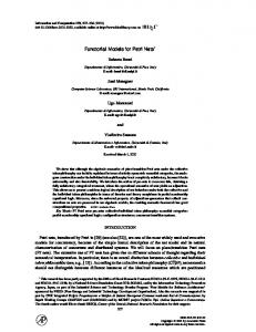
In this step, BOM is transformed into PN model. In the preparatory phase a composed BOM model is parsed using our BOM parser and the objects of state-machines, and corresponding events of all the members of composition are collected. Then the composition is analyzed to check completeness of model in terms of structure of state-machines and the presence of associated events for each state to be able to exit. In case of no such association it is verified whether the particular state is a final state or not. The event pairs are also matched among the member components so that for each receiver component a corresponding sender of an event is present. This procedure is applied to ensure that the composition is structurally correct and suitable to proceed with. For more details see [3]. Finally the BOM model is automatically transformed into a PN model. A PN model is ideally represented using PNML (PN Markup Language) which is an XML-based standard interchange format for PN. We propose the basic transformation algorithm as given in figure 2a. The input for this procedure is a BOM object C of the composed model which is generated by the parser. In order to meet the requirements of PNML, we also assume default values such that tokens at each place are set to zero and arc weights are set to 1. As we are not considering Timed PN in this work so we also set the timed Boolean variable to false. These settings can be modified later for experimentation at the time of execution & analysis. In this algorithm for each state-machine in the composed model (line 2) every state is traversed one by one (line 3) and its corresponding place is created1 in 1
Create functions are used to write XML code to a file according to the PNML notation.
Short Papers of the 22nd IFIP ICTSS, Alexandre Petrenko, Adenilso Simao, Jose Carlos Maldonado (eds.), Nov. 08-10, 2010, Natal, Brazil.
10
Composability Test of BOM based models using Petri Nets
Fig. 1. a) Our Algorithm b) Transformation from BOM to PN
PNML format (line 4). Since a state may have multiple next states and their associated exit events so for each next state (line 5), a place is created (line 6) provided it does not already exist. Then a transition is created for the exit event associated with the next states (line 8). After that an input arc is created from the place to transition (line 9) and an output arc is created from the transition to the next place (line 10). Duplication is avoided in the entire process. This procedure can be graphically viewed in figure 2b, (assuming that the two state-machines have a common exit event) Also the graphical placing (X and Y positions) for each place, transition and arc is handled automatically in such a way that all the places of each member component are aligned in a vertical lane and their transitions are created between the lanes to show the interaction among different components in order to facilitate visibility. When the entire BOM model is traversed, a PNML file is generated that corresponds to the PNML standard and can be used in any PN simulation tool for execution.
2.2
Petri Net Analysis
In the analysis step, we perform Reachability analysis on the PNML model generated in the previous step with user given input parameters. To initiate this procedure we use PIPE library to construct a reachability tree and populate it with our PNML model generated in the previous step. We perform this operation programmatically to facilitate automation. After the initialization of the root marking, the tree recursively expands by constructing further markings until all the markings of the model have been created. If no more marking can be created, i.e., no further transition is enabled it reaches a dead marking. By detecting a dead marking in the tree, we assert that a deadlock is detected provided that it is not a final marking. We propose a minor change in the original definition of deadlock in a Dead (or L0-live) PN as some models may have terminal points e.g., when a Final State in a finite State-machine is reached. So we define a “Final Marking” as a successful termination point which is not considered as a dead marking even though no further transitions could be fired. Thus we propose a deadlock detection method in which we find at least one dead marking from
Short Papers of the 22nd IFIP ICTSS, Alexandre Petrenko, Adenilso Simao, Jose Carlos Maldonado (eds.), Nov. 08-10, 2010, Natal, Brazil.
I. Mahmood, R. Ayani, V. Vlassov and F. Moradi
11
where no further transitions could be fired, provided it is not a final marking. We input the final marking as a parameter for reachability analysis.
3
Case Study
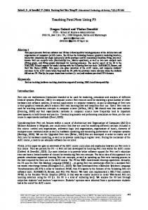
In this section we discuss a restaurant case study to test our verification approach. This is a simple composed model of two BOM components namely Customer and Waiter. In step 1, Restaurant BOM is parsed and the corresponding objects are generated and the model is transformed into PNML format using our proposed algorithm. Figure 2a represents the sequence diagram of the restaurant. Statemachines of customer and Waiter are presented in Figure 2b where as the generated PN is illustrated in 2c.
Fig. 2. a) Sequence Diagram b) Statemachine c)PN
When PN model is executed in PIPE simulator, a token is dispatched from the Arrive place representing the arrival of a customer who orders food. But it requires an available Waiter from Ready place to proceed. After Order Food transition is fired, one token will be produced to Waiting and the other will be produced to Preparing Food, place. In the same way, all the interactions between customer and waiter will continue, until the customers have reached Leaving whereas the waiter goes back to Ready. In step 2, the reachability analysis module is initiated and the final marking parameter [0,0,0,5,1,0,0] (i.e., all five customers leave the restaurant and the waiter is back to ready) is given as input to distinguish it from the dead markings. When the module completed the execution, it verified that the model is deadlock free as only one dead marking was detected in the tree which was exempted by the final marking parameter. The Reachability Tree can be viewed at: http://web.it.kth.se/~imahmood/SimpleRestaurant.html. In the tree each node (in blue) represents a marking and is denoted by a number and transitions are the arrows connecting next marking. From the tree it can be seen that node 50 (in green) is the only dead marking from where no further transition is possible. Thus we verify that although the model terminates it does not have a deadlock.
Short Papers of the 22nd IFIP ICTSS, Alexandre Petrenko, Adenilso Simao, Jose Carlos Maldonado (eds.), Nov. 08-10, 2010, Natal, Brazil.
12
Composability Test of BOM based models using Petri Nets
In a different experiment we introduced another component Kitchen in the composed model. Same procedure was applied however it was noted that few dead markings were detected because, there are some situations in which kitchen is in the cooking place and can be released only when waiter takes food to serve, whereas waiter is waiting for the kitchen to take more orders. This results in a potential deadlock which may or may not occur depending on the sequence of transitions fired. This potential deadlock is detected by our framework. The figures of the PN model and reachability tree of this experiment cannot be shown due to space limitations and can be viewed at: http://web.it.kth.se/ ~imahmood/Restaurant.html . We also encourage interested readers to view more case studies at our web site: http://web.it.kth.se/~imahmood
4
Summary and Conclusion
In this paper we discuss composability test of BOM based compositions using PN. We suggest an algorithm to transform a composed BOM model into a standard PN format known as PNML which can further be used with any PN analysis tool that conforms to this standard. We however suggest using PIPE tool in our framework and provide a technique to detect deadlocks in the composed model. Finally we explain the entire process using a Restaurant case study. We are further interested to consider alternative techniques in the PN to extend the capability of our verification process, such as Timed PN and Colored PN to test and verify more realistic system models. We also are inclined to apply different state space reduction techniques to our framework in order to solve the state explosion problem and optimize the verification process.
References 1. Chung, E., Kimber, T., Kirby, B., Master, T., Worthington, M.: Platform independent petri net editor. Tech. rep., Imperial College, London, Project Report (2007) 2. Gustavson, P.: Guide for base object model (bom) use and implementation. Tech. Rep. SISO-STD-003-2006, Simulation Interoperability Standard Organizations (SISO), Orlando, FL USA (2006) 3. Mahmood, I., Ayani, R., Vlassov, V., Moradi, F.: Statemachine matching in bom based model composition. In: Proc. 13th IEEE/ACM Int. Symp. Distributed Simulation and Real Time Applications DS-RT ’09. pp. 136–143 (2009) 4. Murata, T.: Petri nets: Properties, analysis and applications 77(4), 541–580 (1989) 5. Peterson, J.L.: Petri nets. Computing Surveys vol. Vol 9, no. No. 3 (September 1977) 6. Petty, M.D., Weisel, E.W.: A theory ofsimulation composability. Tech. rep., Virginia Modeling Analysis & Simulation Center, Old Dominion University, Norfolk, Virginia (2004)
Short Papers of the 22nd IFIP ICTSS, Alexandre Petrenko, Adenilso Simao, Jose Carlos Maldonado (eds.), Nov. 08-10, 2010, Natal, Brazil.
A. Bertolino, E. Cartaxo, P. Machado, E. Marchetti and J. Ouriques
13
Test Suite Reduction in Good Order: Comparing Heuristics from a New Viewpoint Antonia Bertolino1 , Emanuela Cartaxo2 , Patr´ıcia Machado2 , Eda Marchetti1 , and Jo˜ ao Felipe Ouriques2 {antonia.bertolino,eda.marchetti}@isti.cnr.it 1 ISTI-CNR, Via Moruzzi, 1, 56124. Pisa, Italy {emanuela,patricia,jfelipe}@dsc.ufcg.edu.br, 2 GMF-UFCG, Av. Apr´ıgio Veloso, 882. Campina Grande, Brazil
Abstract. A new perspective in assessing test suite reduction techniques based on their rate of fault detection is introduced in this paper. This criterion, which is standard in assessing test-suite prioritization, has never been used for reduction. Our proposal stems from the consideration that under pressure testing could be stopped before all tests in the reduced test-suite are run, and in such cases the ordering in the reduced test-suite is also important. We compare four well-known reduction heuristics showing that by considering the rate of fault detection, the reduction technique to be chosen when time is an issue might be different from the one performing the best when testing can be completed. Keywords: Heuristics, Test Ordering, Test Reduction
1
Introduction
Defining a suitable test suite that detects as many faults as possible is a challenge to software testers. To address it, test requirements are often defined as coverage criteria to be met, based on the assumption that a test suite that achieves the coverage is an effective one. Moreover, due to resource constraints, a test manager goal is to define a minimum such suite. In practice, test suites have a number of redundant test cases, particularly the ones that are automatically generated. In this sense, test suite reduction techniques have been investigated [1]. These techniques aim at reducing the size of a test suite as far as the test requirements can be reached. Therefore, test suite reduction is a key strategy to be applied independently of the kind of testing to be performed. However, even this reduced test suite can be too big to meet resource constraints, and the tester may still face the problem of selecting only a few test cases. This issue has been mostly investigated in regression testing, where tests have to be periodically re-executed. In this case, prioritization techniques have been applied to define an order to execute the regression test cases by increasing the chances of early fault detection during retesting [2]. Several recent studies have compared reduction techniques considering their efficacy in decreasing test-suite size and their impact on fault detection effectiveness. Chen and Lau [3] present guidelines for choosing the most appropriate
Short Papers of the 22nd IFIP ICTSS, Alexandre Petrenko, Adenilso Simao, Jose Carlos Maldonado (eds.), Nov. 08-10, 2010, Natal, Brazil.
14
Test Suite Reduction in Good Order: Comparing Heuristics from a New ... 2
Test Suite Reduction in Good Order
heuristic-based technique according to the size of the reduced suite. Zhong et al. [4] also consider genetic algorithms and the execution time of the suite. On the other hand, Rothermel et al. [5] focus on fault detection capability. Regarding model-based testing, Heimdahl and George [6] present a study based on coverage criteria such as Variable Domain, Transition, Decision, Decision Usage, MC/DC, MC/DC usage. Also considering coverage, Wong et al. [7] conclude that representative sets regarding fault detection capability can be reached. Finally, Harrold et al. [8] investigate separately two algorithms for test suite reduction and one for test suite prioritization taking as test requirement MC/DC coverage. Nevertheless, these studies analyze the reduced test-suite as a whole, without considering the order in which the tests are executed. We consider here test ordering during test reduction, which is different from test prioritization during regression testing. The problem of executing first the most effective test cases while covering test requirements can be handled by following a test selection order based on the choices of the reduction technique, since they usually pick one-by-one a test case from the original test suite. In this sense, the best reduction technique to be applied in a particular context would be the one that meets the test requirements and also chooses the test cases in an order that favors the most relevant ones, particularly regarding fault detection effectiveness. To the best of our knowledge, how the effectiveness of a test reduction heuristic varies in relation to the number of test cases executed is something that has not be analyzed so far. This paper proposes a new viewpoint in evaluating test suite reduction techniques by also considering the order by which test cases are selected (Section 2). For this, two real-world case studies are conducted by considering four wellknown reduction heuristics (Section 3). To evaluate the results, we measure the rate of fault detection, which is commonly applied to assess prioritization techniques. As a result, some techniques may be more effective in selecting up to a certain number of test cases, even if they may not remain the best ones for a bigger number of test cases up to the limit of the complete reduced test suite (Section 4). Note that the goal is to illustrate that techniques can yield a different performance regarding fault detection when ordered subsets are considered and then to motivate evaluation of reduction techniques from this new viewpoint. Providing generally valid conclusions on which heuristic is the most effective is out of scope.
2
Background and Motivation
From Harrold et al. [1], considering generically a test requirement as a statement, a block, a decision, and so on, a test suite reduction can be defined: Given: A test suite T S, a set of test requirements Req = { Req1 , Req2 , . . . , Reqn } to be covered, and subsets of T S: T S1 , T S2 , . . . , T Sn , where each test case of T Si can be used to test Reqi : A representative subset RS of T S that satisfies all of the Req’s must have at least one test case for each Req.
Short Papers of the 22nd IFIP ICTSS, Alexandre Petrenko, Adenilso Simao, Jose Carlos Maldonado (eds.), Nov. 08-10, 2010, Natal, Brazil.
A. Bertolino, E. Cartaxo, P. Machado, E. Marchetti and J. Ouriques Test Suite Reduction in Good Order
15 3
Fig. 1. Test Case Order
Thus the goal of test suite reduction is to construct a subset (RS) of the original test suite that still provides 100% coverage of test requirements. Considering test case prioritization, the problem can be defined as follows [2]: Given: T S, a Test Suite; P T S, a set of permutations of T S; and, f , a function from P T S to real numbers. Find: T S0 ∈ P T S | ∀ T S00 (T S00 ∈ P T S) (T S00 = 6 T S0) ; f (T S0) ≥ f (T S00). The objective function is defined from the goal of the prioritization. Then, a set of permutations P T S is obtained and the P T S0 that has the biggest f (T S0) is chosen. When the goal is to increase fault detection, there is a metric largely used in the literature, named Average Percentage of Fault Detection – APFD. The highest APFD value, the fastest and the best the fault detection rates [2]. Usually heuristics for test suite reduction and prioritization are used in isolation. The ideal solution would be to maximize the number of failures detected while selecting a subset of non-redundant test cases that covers all requirements. To motivate such an approach, let us consider the same toy example presented in [2], where a program is supposed to contain 10 faults and a test suite of 5 test cases, called for simplicity (A,B,C,D,E), is available. When all test cases are executed, independently of their order, the percentage of fault detection is always 100%. To select the best prioritization technique, the APFD measure reached by the associated combination of test cases has been proposed. According to [2], the sets (A,B,C,D,E), (E,D,C,B,A), (C,E,B,A,D) yield respectively the following APFD values: 50%, 64 % and 84%. Hence the third one is the best. Now, suppose we apply three different reduction techniques on the same test suite, obtaining the following reduced sets: TS1 = (B,E,D); TS2 = (A,E,B,C); TS3 = (B,A,C,D,E), all reaching 100% requirements coverage. TS1 performs the best in terms of test size reduction even if TS1 discovers the 70% of the faults, while TS2 and TS3 detect the 100%. As shown in Figure 1, the best technique considering the APFD measure would be TS3, but it is the one having the worst performance in terms of test suite reduction. A practical compromise should consider both the number of test cases executed and the rate of fault detection. On the other hand, if for any reasons the test phase needs to be stopped after only two test case are executed, recalculating the APFD of the first two tests in TS1, TS2, TS3 the following results can be observed: TS1 r = (B,E) detects 7 faults and reaches the 35.5% of APFD; TS2 r = (A,E) detects 5 faults and reaches the 22.5% of APFD; TS3 r = (B,A) detects 4 faults and reaches the
Short Papers of the 22nd IFIP ICTSS, Alexandre Petrenko, Adenilso Simao, Jose Carlos Maldonado (eds.), Nov. 08-10, 2010, Natal, Brazil.
16
Test Suite Reduction in Good Order: Comparing Heuristics from a New ... 4
Test Suite Reduction in Good Order
30% of APFD. In this case the best APFD belongs to TS1 and not anymore to TS3. Thus if testing is stopped before all test cases in the reduced test-suite are run, the ordering in the reduced test-suite is important for selecting the most effective test strategy. This is why we propose to mix the concepts of reduction and prioritization.
3
Case Studies
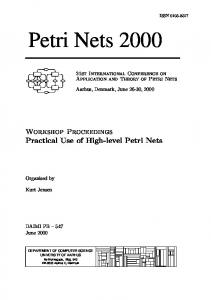
In two real-world case studies, provided by Motorola, we compared four wellknown test suite reduction heuristics – G, GE, GRE and H [3] – from the new viewpoint. The idea is to measure the rate of fault detection to show that the techniques based on these heuristics may present a different performance when considering the progressive coverage of selected test cases up to 100% coverage of the test requirements. For each application, Motorola Software Engineers elaborated the use case documents [9]. From these documents, Labelled Transitions Systems (LTS) are generated and from these, the test cases are obtained by using the LTS-BT tool [10]. We considered transition coverage as test requirement. The applications selected for the case studies are: Application 1 – TaRGeT, a desktop application – with 84 test cases that present redundancy (cover the same requirement); and Application 2 – Direct License Acquisition, a feature for mobile phone applications – with 28 test cases that present redundancy, but each test case has at least one transition that is only covered by it. The test cases were manually executed and the failures captured were associated with faults that can be detected by the suite. For Application 1, 13 faults have been defined, whereas for Application 2, 2 faults have been defined. We have 4 reduced test suites (one for each heuristic) to be compared. Each heuristic was run 20 times. We collected the reduced test suite size for each execution and the number of the failures. For Application 1, the average of reduced test suite size for G, GE, GRE is 74 and for H is 74.45 and the number of faults are for G, GE, GRE and H, respectively, 10.4, 10.4, 10.5 and 10.75. For Application 2, the heuristics did not reduce the test suite, since each of the 28 test cases has at least 1 transition that is covered only by it. So, all heuristics kept on the reduced test suite the same number of test cases of the original test suite and, consequently, the rate of fault detection is not decreased. To evaluate fault detection effectiveness, we constructed box plots to show the distribution of faults in 20 executions. For lack of space, we only report the box plots obtained for Application 1 respectively for heuristics GE, GRE, Greedy and H (Figure 2-5). For Application 1: if the tester is able to execute only 1-5 test cases, then GE and GRE is the best choice (1 fault detected when compared to 0-1 for the others). From 6-20 test cases, G is the best choice (from 3 to 7 faults when compared to from 2 to 6 for the others), whereas for more than 20 test cases, H is the best choice. For Application 2: if the tester is able to execute only 1-10 test cases, then H is the best choice (1-2 faults detected when compared to 0-1 for the others). For more than 10 test cases, GE and GRE are the best
Short Papers of the 22nd IFIP ICTSS, Alexandre Petrenko, Adenilso Simao, Jose Carlos Maldonado (eds.), Nov. 08-10, 2010, Natal, Brazil.
A. Bertolino, E. Cartaxo, P. Machado, E. Marchetti and J. Ouriques Test Suite Reduction in Good Order
Fig. 2. Application 1 - GE
Fig. 3. Application 1 - GRE
Fig. 4. Application 1 - Greedy
Fig. 5. Application 1 - H
17 5
choice (always detect 2 faults). It is important to highlight that GE and GRE heuristics present the same behaviour for all positions. From these case studies, it can be noticed that by analysing the rate of fault detection, it is possible to observe which technique can be more effective, depending on the goals of the tester. Some techniques are more effective when only the first selected test cases can be handled, whereas others improve their performance as more test cases are considered. Of course, the results observed cannot be generalised to other applications different from the two case studies considered here. The presented case studies are just meant to illustrate the differences that may arise. Wider experiments need to be executed to get more general conclusions.
4
Conclusions
Common practice to compare reduction techniques considers that all the test cases in the reduced test suite will be executed. However, if under budget constraints testing is stopped in advance than planned, the test methodology chosen for selecting the test cases during the planning could not be anymore the best choice. In this paper we showed how the fault detection effectiveness of the reduction heuristics could change when testers are forced to drastically reduce the number of test cases scheduled for a certain software. We considered four well-known reduction heuristics – G, GE, GRE and H – and measured their progressive rate of fault detection on two real-world applications. The analysis of the case studies evidences how the performance of the four heuristics can be really influenced by the number of the test cases executed.
Short Papers of the 22nd IFIP ICTSS, Alexandre Petrenko, Adenilso Simao, Jose Carlos Maldonado (eds.), Nov. 08-10, 2010, Natal, Brazil.
18
Test Suite Reduction in Good Order: Comparing Heuristics from a New ... 6
Test Suite Reduction in Good Order
Of course the studies performed so far cannot be used for general conclusions and further investigations are necessary. Our goal was to show that the metrics adopted so far for assessing the relative effectiveness of various reduction approaches probably do not completely match a reality in which the testing phase can be shortened depending on time and cost constraints. Our results suggest that probably a new way of measuring the performance of various heuristics could be necessary. Identifying such a new assessment approach is part of our future work as well as executing more case studies and experiments.
5
Acknowledgements
This work was partially supported by the National Institute of Science and Technology for Software Engineering (INES1 ), funded by CNPq, grant 573964/2008-4 and CT-INFO/CNPq (Process 140074/2008-2).
References [1] Harrold, M.J., Gupta, R., Soffa, M.L.: A methodology for controlling the size of a test suite. ACM Trans. Softw. Eng. Methodol. 2 (1993) 270–285 [2] Elbaum, S., Malishevsky, A.G., Rothermel, G.: Prioritizing test cases for regression testing. In: In Proc. of the Int. Symposium on Soft. Test. and Analysis, ACM Press (2000) 102–112 [3] Chen, T.Y., Lau, M.F.: A simulation study on some heuristics for test suite reduction. Information & Software Technology 40 (1998) 777–787 [4] Zhong, H., Zhang, L., Mei, H.: An experimental comparison of four test suite reduction techniques. In: ICSE ’06: Proc. of the 28th Int. Conf. on Soft. Engineering, New York, NY, USA, ACM (2006) 636–640 [5] Rothermel, G., Harrold, M.J., Ronne, J.V., Hong, C.: Empirical studies of testsuite reduction. Journal of Soft. Test., Verification, and Reliability 12 (2002) 219–249 [6] Heimdahl, M.P.E., George, D.: Test-suite reduction for model based tests: Effects on test quality and implications for testing. In: ASE ’04: Proc. of the 19th IEEE Int. Conf. on Automated Soft. Engineering, Washington, DC, USA, IEEE Computer Society (2004) 176–185 [7] Wong, W.E., Horgan, J.R., Mathur, A.P., Pasquini, A.: Test set size minimization and fault detection effectiveness: A case study in a space application. Journal of Systems and Software 48 (1999) 79–89 [8] Jones, J.A., Harrold, M.J.: Test-suite reduction and prioritization for modified condition/decision coverage. IEEE Trans. Softw. Eng. 29 (2003) 195–209 [9] Nogueira, S., Cartaxo, E., Torres, D., Aranha, E., Marques, R.: Model based test generation: An industrial experience. In: 1st Workshop on Systematic and Automated Soft. Testing - SBBD/SBES 2007, Joao Pessoa, PB, Brazil (2007) [10] Cartaxo, E.G., Andrade, W.L., Neto, F.G.O., Machado, P.D.L.: LTS-BT: a tool to generate and select functional test cases for embedded systems. In: SAC ’08: Proc. of the 2008 ACM Symposium on Applied Computing. Volume 2., New York, NY, USA, ACM (2008) 1540–1544 1
www.ines.org.br
Short Papers of the 22nd IFIP ICTSS, Alexandre Petrenko, Adenilso Simao, Jose Carlos Maldonado (eds.), Nov. 08-10, 2010, Natal, Brazil.
´ A. Banzi, G. Pinheiro, J. Arias, T. Nobre, A. Pozo and S. Vergilio
19
A Multiobjective Tabu Search Algorithm for Reducing Mutation Test Costs ´ Adam Banzi, Gabriel Pinheiro, Jo˜ao Carlos Arias, Tiago Nobre, Aurora Pozo, and Silvia Regina Vergilio ⋆ Computer Science Department, Federal University of Paran´ a CP: 19081, CEP 19031-970, Curitiba, Brazil {adam,gabrielb,joao,tiagon,aurora,silvia}@inf.ufpr.br
Abstract. Some strategies were introduced in the literature to decrease mutation test costs, and to determine sets of essential mutation operators to reduce the number of mutants to be executed without decreasing the mutation score. However, the operator selection, in practice, may include real constraints and is dependent on diverse factors. In fact this is a multiobjective problem, that is, this problem does not have a single solution. Different sets of operators exist for multiple objectives to be satisfied, and some restrictions can be used to choose among the existing sets. To make this choice possible, we introduce in this paper a multiobjective approach based on a Tabu search algorithm. The algorithm was evaluated in a set of C programs and generated a set of solutions that dominate the solutions obtained by other traditional strategies. Keywords: fault-based test, essential mutation operators
1
Introduction
The mutation score is an important measure to evaluate the quality of the test cases. It is usually obtained by executing a lot of mutant programs generated by a set of operators that describe faults. However, for a program, some operators can generate unnecessary and redundant mutants, associated to test cases that do not contribute to increase the score, and are not supposed to reveal additional faults. This makes mutation test very expensive, and to reduce its costs, some strategies were proposed. For example: Randomly Selected X% Mutation [1]; Constrained Mutation [9]; and N Selective Mutation. Other works investigate the determination of essential operators for Fortran [7] and C languages [2, 8] to reduce the number of mutants to be executed without decreasing the global score. However, the mentioned works that address the selection of essential operators present some limitations. The first one [6] is that the experiments described by most works were conducted by using small programs with simple data and control structures. Another problem is that the strategies to determine the set ⋆
This work is partially supported by CNPq
Short Papers of the 22nd IFIP ICTSS, Alexandre Petrenko, Adenilso Simao, Jose Carlos Maldonado (eds.), Nov. 08-10, 2010, Natal, Brazil.
20
A Multi-objective Tabu Search Algorithm for Reducing Mutation ...
of operators are empirical, and provide at the end only a specific set of essential operators, to maximize the mutation score with a low number of mutants. They are not able to generate different good sets according to different objectives. The operator selection, in practice, may include real constraints and is dependent on diverse factors besides the number of mutants and score, such as: number of test data, execution time, number of revealed faults, number of equivalent mutants, and so on. In fact this is a multiobjective problem, that is, this problem does not have a single solution. Different sets of operators exist for multiple objectives to be satisfied, and some restrictions can be used to choose among the existing sets. According to the test objectives and resources, we can desire to use a different essential set of operators that prioritize a certain factor. To make this choice possible, we introduce in this paper a multiobjective Tabu-search algorithm. To allow comparison with the traditional strategies, we illustrate the use of the algorithm in the unit test of real C programs, with two objectives: number of mutants and score. Graphical analysis shows that the solutions presented by the algorithms are better than the solutions of the traditional strategies considering both objectives. This paper is organized as follows. Section 2 introduces the multiobjective formulation of the mutant operator selection problem and describes the implemented algorithm. Section 3 presents experimental results. Section 4 concludes the paper and presents new directions of research.
2
The Multiojective Approach
Optimization problems with two or more objective functions are called multiobjective. In such problems, the objectives to be optimized are usually in conflict, which means that they do not have a single solution. In this way, the goal is to find a good trade-off of solutions that better represent the possible compromise among the objectives, that is, solutions that are not dominated by any other in the objective space. A set of non-dominated objective solutions is called Pareto optimal and the set of all non-dominated solutions is called Pareto Front. We can observe that the problem of selecting a set of operators is in fact multiobjective. It may involve a number Q of different objectives to be optimized: mutation score, number of test cases, number of mutants, number of equivalent mutants, number of faults to be revealed, execution time, and so on. Given a program P , a set of mutation operators O, and a vector of Q objective functions, fi , i = 1...q. The problem is to find a subset O′ , such that O′ is the Pareto optimal set with respect to the objective functions, fi , i = 1...q. The chosen representation for the problem is simple, with the solution being represented by a vector whose positions assume an integer number in the interval [1, N ], being N the number of the mutation operators. Each operator can not appear more than once in the vector. However, the front is dependent on the program, but, it is very expensive to execute the optimization algorithms every time that the test occurs, because of this, the essential sets of operator can be previously established from the
Short Papers of the 22nd IFIP ICTSS, Alexandre Petrenko, Adenilso Simao, Jose Carlos Maldonado (eds.), Nov. 08-10, 2010, Natal, Brazil.
´ A. Banzi, G. Pinheiro, J. Arias, T. Nobre, A. Pozo and S. Vergilio
21
analysis of different fronts obtained for similar programs (in the same application domain). To allow comparison with traditional strategies, in this work, we will take a benchmark, composed by six C programs from the same domain and will consider unit test and two objectives: number of mutants and mutation score. Hence, the problem is the search for sets of mutation operators that maximize the mutation score and minimize the number of mutants. The Tabu Search approach was proposed by Glover [4] to allow hill climbing and avoid local optima. The basic principle of Tabu Search is to pursue the search whenever a local optimum is encountered by allowing non-improving states. Cycling back to previously visited solutions is prevented by the use of memories, called tabu lists, that keep the recent history of the search. In [3] a Multiobjective version of the Tabu algorithm was proposed, the MTabu algorithm (Multiobjective optimization using Tabu search), which runs over a neighborhood using Pareto’s concepts. The algorithm works with the following lists: candidateList - List that receives all the non dominated neighbors of the current solution; paretoList - List that contains already explored non dominated solutions; and tabuList - List that keeps all explored solutions. The MTabu algorithm (see Algorithm 1) begins generating a random solution (SeedSolution). This solution, called currentSolution, is expanded and the neighborhood is kept in candidateList. After then, paretoList and tabuList are updated with the currentSolution. These steps are an iteration of the inner loop. This inner loop is repeated a number of times depending on the maximum number of iterations (max iterations). An external loop controls the number of different randomly generated solutions (maxseed) to be explored.
Algorithm 1 Pseudocode of MTabu. Initialize numberseed, candidateList, paretoList, tabuList; while numberseed < maxseed do counter = 0; currentSolution = SeedSolution(numberseed); while counter < max iterations do for i = 1 to neighborhoodSize do candidate = neighbor(currentSolution); if (not contains(tabuList, candidate)) then Evaluate(candidate); Update(candidateList, candidate); end if end for Update(tabuList, currentSolution); Update(paretoList, currentSolution); currentSolution = randomlySelectedCandidate(candidateList); counter =+ ; end while numberseed =+ ; end while
Short Papers of the 22nd IFIP ICTSS, Alexandre Petrenko, Adenilso Simao, Jose Carlos Maldonado (eds.), Nov. 08-10, 2010, Natal, Brazil.
22
A Multi-objective Tabu Search Algorithm for Reducing Mutation ...
3
Experiments
We used a set of C programs from SIR [5]. These programs have been used as benchmark for many software testing works [6]. All the test data available in the repository were submitted to Proteum, version 1.4 (Linux), and the 71 operators of this version were used. The alive mutants were considered equivalent. The test cases that did not contribute to increase the mutation score in the order of execution were also discarded. At the end, we obtained for each program a test set T that we will call M -adequate. We applied some well known strategies to reduce the number of mutants. Each strategy applies a subset of operators, O′ ⊆ O, which generates a number M ′ of mutants. After this, we determined a set T ′ ⊆ T that is M ′ -adequate, that is, test cases of T that really contribute to increase the mutation score in the same initial execution order. The score obtained considering M and T ′ was then calculated and used in the comparison. In the sequence, we provide a brief description of how the sets O′ and M ′ for each strategy were obtained: a) Randomly Selected X% Mutation: this strategy was implemented to randomly select 10%, 20% and 40% of the mutants generated by each mutation operator. Hence, O′ = O; b) N Selective Mutation: we considered three values for N : 5, 10 and 20. Then, the mutants generated by N = 5 operators that generated more mutants were excluded from the total set M , and a set O′ was used, with (O − 5) operators. Similarly for the other values of N ; c) Essential operators for unit test from Barbosa et al [2]: using the following set of operators: {SWDD, SMTC, SSDL, OLBN, ORRN, VTWD, VDTR, CCCR, CCSR}. In this case O′ = 9. The Tabu-search algorithm was run ten times with: maxseed=5; max itera− tions= 500; tabuListSize=20; neighborhoodSize=10. The Tabu fronts are displayed in Figures 1 to 6, and are used in the comparison with the traditional strategies. To a better visualization, some strategies with bad results do not appear in the figures. We represent only the best points from the applied strategies. For printtokens, the best coverage result of the traditional strategies was obtained by the Selective (N = 5) (score equal to 1), but, the number of mutants is very high (1774), because of this, the correspondent point is not displayed in the graph. MTabu reaches the same coverage with a lower number of mutants (525). This result is also better, in terms of coverage and number of mutants, than the results of Random (N = 20%), Random (N = 40%), Selective (N = 10) and Essential operators. The strategies Random (N = 10%) and Selective (N = 20) have results with lower number of mutants but lower coverage too, in this case, the solution of MTabu (with score = 0.9987 and number of mutants = 271) dominates both. For printtokens2, the best coverage result of the traditional strategies, was obtained by using the Essential operators (score equal to 1), but again, the number of mutants is very high (1221). MTabu reaches the same coverage with a lower number of mutants (535). This result is better than that ones of Random (N = 20%), Random (N = 40%), Selective (N = 5) and Selective (N = 10). The strategies Random (N = 10%) and Selective (N = 20) have results with lower
Short Papers of the 22nd IFIP ICTSS, Alexandre Petrenko, Adenilso Simao, Jose Carlos Maldonado (eds.), Nov. 08-10, 2010, Natal, Brazil.
´ A. Banzi, G. Pinheiro, J. Arias, T. Nobre, A. Pozo and S. Vergilio
23
Fig. 1. Program printtokens.
Fig. 2. Program printtokens2.
Fig. 3. Program schedule.
Fig. 4. Program schedule2.
Fig. 5. Program totinfo.
Fig. 6. Program tcas.
number of mutants but lower coverage too, in this case, the solution of MTabu (with score = 0.9988 and number of mutants = 195) dominates both. The remarks made above are valid to the other programs. For schedule, the best results of the traditional strategies, in terms of mutation score, was obtained by Selective (N = 5) (score equal to 0.9989) with a high number of mutants (907). MTabu reaches the score equal to 1 with a lower number of mutants (690). This result is better than that one obtained by Random (N = 40%). The other strategies have lower coverage and always it is possible to obtain better results with MTabu as observed in Figure 3. In sum, from all figures we observe that the results provided by the traditional strategies are always dominated by the results of MTabu.
Short Papers of the 22nd IFIP ICTSS, Alexandre Petrenko, Adenilso Simao, Jose Carlos Maldonado (eds.), Nov. 08-10, 2010, Natal, Brazil.
24
A Multi-objective Tabu Search Algorithm for Reducing Mutation ...
4
Conclusions
This paper described a multiobjective algorithm using Tabu search (MTabu) to the mutation operator selection problem. To allow comparison with the traditional approach, two objectives were used: number of mutants and mutation score. The results provided by the traditional strategies are always dominated by the results of MTabu, or in other words, there are a lot of solutions that are better than that ones obtained by the traditional strategies. Differently of the traditional strategies, the approach allows that other factors that may influence the selection can be considered. Each solution represents a set of operators, and by analysing the fronts, different sets of essential operators can be generated. A set should be chosen according to the real test restrictions. If the tester is interested in a balance among the objectives, all the solutions can be used. However, if an objective has higher priority, the best solutions considering such objective should be taken. A procedure to determine a set of essential operators according to priorities given to each objective is now being automated, and other evaluation experiments should be conducted. Now, we are investigating the use of three objectives considering the minimization of equivalent mutants. Other research directions include to evaluate objective functions related to the characteristics of the programs being tested, and to explore the use of the approach in other contexts, such as: mutation interface and Java programs.
References 1. Acree, A., Budd, T., DeMillo, R., Lipton, R., Sayward, F.: Mutation analysis. School of Information and Computer Science, Georgia Institute of Technology (1979) 2. Barbosa, E., Maldonado, J., Vincenzi, A.: Towards the determination of sufficient mutant operators for C. Sw Test. Verification and Reliability 11, 113–136 (2001) 3. Baykasoglu, A., Owen, S., Gindy, N.: A Taboo Search Based Approach to Find the Pareto Optimal Set in Multiple Objective Optimisation. Journal of Engineering Optimization pp. 731–748 (1999) 4. Glover, F.: Future Paths for Integer Programming and Links to Artificial Intelligence. Comput. Open Res. pp. 13:533–549 (1986) 5. Hutchins, M., Foster, H., Goradia, T., Ostrand, T.: Experiments of the effectiveness of data data flow and control flow-based W-test adequacy criteria. In: 16th International Conference on Software Engineering (ICSE 1994). pp. 191–200 (1994) 6. Namin, A.S., Andrews, J.H., Murdoch, D.: Sufficient Mutation Operators for Measuring Test Effectiveness . In: ICSE’2008. pp. 351–360 (2008) 7. Offutt, A., Lee, A., Rothermel, G., Untch, R., Zapf, C.: An experimental determination of sufficient mutant operators. ACM Transactions on Software Engineering and Methodology 2(5), 99–118 (1996) 8. Vincenzi, A., Maldonado, J., Barbosa, E., Delamaro, M.: Essential Interface Operators: A Study Case. In: Proceedings of the 13th Brazilian Symp. on Software Engineering. pp. 373–391 (1999), in Portuguese 9. Wong, W., Mathur, A.: Reducing the cost of mutation testing: An empirical study. The Journal of Systems & Software 31(3), 185–196 (1995)
Short Papers of the 22nd IFIP ICTSS, Alexandre Petrenko, Adenilso Simao, Jose Carlos Maldonado (eds.), Nov. 08-10, 2010, Natal, Brazil.
O. L. N. Timo, H. Marchand and A. Rollet
25
Automatic Test Generation for Data-Flow Reactive Systems with time constraints? Omer Nguena Timo1 , Herv´e Marchand2 , and Antoine Rollet1 1
LaBRI (University of Bordeaux - CNRS), Talence, France 2 INRIA, Centre Rennes-Bretagne Atlantique Abstract. In this paper, we handle the problem of conformance testing for data-flow critical systems with time constraints. We present a formal model (Variable Driven Timed Automata) adapted for such systems inspired from timed automata using variables as inputs and outputs, and clocks. In this model, we consider urgency and the possibility to fire several transitions instantaneously. We present a conformance relation for this model and we propose a test generation method using a test purpose approach, based on a region graph transformation of the specification.
1
Conformance testing with VDTA
We define the conformance testing relation tvco for Data-flow reactive systems. such systems are characterized by the fact that they interact with their environment in a continuous way by means of continuous input and output set of events (taking their values in (possibly) infinite domains), while obeying some timing constraints. In this framework, continuous means that the values of the inputs events can be updated at anytime, while the value of the outputs events can always be observed. We choose to model our sytems by Variable Driven Timed Automata (VDTA) [7], a variant of timed automata [2] with only urgent transitions (i.e fired as soon as constraints are true). VDTA rather uses variables communication mechanism than synchronising actions. We first introduce the VDTA model and then our conformance relation tvco. 1.1 Variable driven timed automata (VDTA) Given a set of variables V , each variable Vi ∈ V ranges over a (infinite) domain Dom(Vi ) in N, Q+ or R+ . We denote G(V ) the set of variable constraints defined as boolean combinations of constraints of the form Vi ./ c with Vi ∈ V , c ∈ Dom(Vi ) and ./∈ {}. For a set V , a variable assignment for V is a tuple Πi∈[1..n] ({Vi } × (Dom(Vi ) ∪ {⊥})) and we denote by A(V ) the set of variable assignments for V . Given G ∈ G(V ) and a valuation v ∈ Dom(V ), we write v |= G when G(v) ≡ true. Given a valuation v = (v1 , · · · , vn ) of V and A ∈ A(V ), we define the valuations v[A] as v[A](Vi ) = c if (Vi , c) ∈ A and c 6= ⊥, and v[A](Vi ) = vi otherwise. Intuitively, (Vi , c) of A requires to assign c to Vi if c is a constant from Dom(Vi ); otherwise c is equal to ⊥ and no access to Vi should be done. The identity IdV ∈ A(V ) lets unchanged all the variables of V . We define the constraint G[A] = {v[A] | v |= G}. P rojVi (G) denotes the constraint such that (v1 , · · · , vi−1 , vi+1 , · · · , vn ) |= P rojVi (G) iff ∃vi ∈ Dom(Vi ) such that (v1 , · · · , vn ) |= G. We extend it to a subset V 0 of V and we denote it P rojV 0 (G). ?
This work was supported by French National Agency ANR Testec Project.
Short Papers of the 22nd IFIP ICTSS, Alexandre Petrenko, Adenilso Simao, Jose Carlos Maldonado (eds.), Nov. 08-10, 2010, Natal, Brazil.
26
Automatic Test Generation for Data-Flow Reactive Systems with time ...
Definition 1 (VDTA). A Variable Driven Timed Automaton (VDTA) is a tuple A = hL, X, I, O, l0 , G0 , ∆A i, where L is a finite set of locations, l0 ∈ L is the initial location, G0 ∈ G(I, O) is the initial condition, a constraint with variables in I ∪O and transitions in the transition relation ∆A ⊆ L×G(I, O, X)× A(O) × 2X × L : hl, G, A, X , l0 i ∈ ∆A is a transition such that – G ∈ G(I, O, X) is a boolean combination of elements of G(I), G(O) and G(X) whereas A ∈ A(O) is an assignement on output variables. – X ∈ 2X is a set of clocks that are reset when triggering the transition. G,A,X
In the sequel, we write l −−−−→ l0 when hl, G, A, X , l0 i ∈ ∆A . A is deterministic if G0 is satisfied by at most one valuation (i0 , o0 ); and for all l ∈ L, for all G1 , G2 Gi ,Ai ,Xi
such that l −−−−−−→ li s.t. G1 6= G2 , G1 ∩ G2 is unsatisfiable. A state of a VDTA as above defined is of the form (`, i, o, x) where i, o and x are valuations of input, output and clock variables. A valuation v ∈ Dom(V ) is simply a function that returns the values of the variables in V . If A ∈ A(I) is an assignement on input variables, the valuation i[A] change the value of input variables according to the assignement. If x is clock valuation, X is a subset of clocks, and δ ∈ R+ a delay, the valuation x + δ add δ to each clock value and the valuation x[X 0 ← 0] resets from x all clocks in X . These notions are standard in the literature. Definition 2. The semantics of a VDTA A = hL, X, I, O, l0 , G0 , ∆A i, is a TTS defined by the tuple [[A]] = hS, s0 , Σ, →i where S = L × Dom(I) × Dom(O) × RX + is the (infinite) set of states, s0 = (l0 , i0 , o0 , x0 ) is the initial configuration where x0 is the clock valuation that maps every clock to 0 and (i0 , o0 ) is the only solution of G0 , Σ = A(I) ∪ A(O) ∪ RX + is the (infinite) set of actions, and → is the transition relation with the following three types of transitions:
T1 (l, i, o, x) − → (l0 , i, o[A], x[X ← 0]) if there exists (l, G, A, X , l0 ) ∈ ∆A such that (i, o, x) |= G, A T2 (l, i, o, x) − → (l, i[A], o, x) with A ∈ A(I) if ∀(l, G, A0 , X , l0 ) ∈ ∆A , (i, o, x) 6|= G. δ T3 (l, i, o, x) − → (l, i, o, x + δ) with δ > 0 if for every δ 0 < δ, for every symbolic transition (l, G, X 0 , l0 ) ∈ ∆A , we have (i, o, x + δ 0 ) 6|= G. A
The environment (e.g. the tester) of a system modeled by a VDTA observes all the variables; it can assign a value to an input in I by performing a transition of type T2. Only the system can assign values to outputs in O by performing a transition of type T1. Transitions in A are urgent and output-update transitions T1 are taken prior to input-update T2 and time-elapsing T3 transitions. Notations. We denote → − Ti for transitions of type Ti , i = 1...3. Out(s) = o gives access to the output value of [[A]] in state s = (l, i, o, x) ∈ S. We write A A A s− → when there exists s0 such that s − → s0 otherwise we write s − 6 →. The latter ∗ notation is standard and it extends to sequences in Σ . A run is a sequence of alternating states and actions s = s0 a1 s1 · · · an sn in S.(Σ.S)∗ such that ∀i ≥ ai+1 0, si −→ si+1 . Run(s, [[A]]) denotes the set of runs that can be executed in [[A]] starting in state s and we let Run([[A]]) = Run(s0 , [[A]]). The trace ρ(r) of a run r = s0 a1 s1 · · · an sn is given by the sequence ρ(r) = P rojS (r) = a1 · · · an ∈ Σ ∗ .
Short Papers of the 22nd IFIP ICTSS, Alexandre Petrenko, Adenilso Simao, Jose Carlos Maldonado (eds.), Nov. 08-10, 2010, Natal, Brazil.
O. L. N. Timo, H. Marchand and A. Rollet
27
T r([[A]]) = {ρ(r)|r ∈ Run([[A]])} is the set of traces generated by A. We note CoReach(S) the set of states from which S can be reached in [[A]]. Stable VDTA. Thanks to their priority, several output-update transitions can be triggered in null delay. A stable state is a state from which no output-update transition can be fired. Formally a state s of [[A]] is stable whenever for every A A ∈ A(O), s − 6 →. To leave this state, either the input values need to be updated or we need to let the time elapse. A stable run is a run that ends in a stable state. A VDTA A is stable if there is no loop of unstable states in [[A]]. In the sequel, we shall only consider stable VDTA. Relation with other models. Timed automata [2] and most of its extensions (with delayable, eager [3], lazy transitions and variables [1] or UPPAAL model) use synchronising actions even for passing variable communication values. But the use of synchronising actions is not adequate for variable-based communication systems as the models should describe all synchronisations with the environment and they become rather unclear and big. To our knowledge urgency and variable passing mechanism are not accurately studied in timed systems for model-based testing. Results in [3] show that timed automata and urgent timed automata (with only clock variables) are equivalent in a language point of view. 1.2
Conformance testing relation
Conformance testing consists in checking that an implementation exhibits an observable behavior consistent with its specification. The main idea of conformance relation is that all observable behaviours of the implementation have to be allowed by the specification. Especially: 1. An implementation is not allowed to update a variable in a time (too late or too early) when it is not allowed by the specification. 2. An implementation is not allowed to omit to change a memory-variable at the time it is required by the specification. A general conformance testing activity consists in executing sequences of input and delays and in checking whether the output of the implementation coincide with those of the specification. The tioco relation [5] (a timed extension of ioco [9]) requires to observe all synchronising output actions on sequences (even of duration equals to zero) whereas the conformance relation for VDTA considers the values of outputs in states where many assignements on outputs (state changing) can occur in zero time unit. Each of these output assignement can or cannot be observed depending on the granularities (frequency) of clocks of the tester and the implementation. We assume the same granularity and thus the outputs are observed only when the implementation is in stable states. Given a stable state s, we will thus be interested in the next stable states (or a singleton if the VDTA is deterministic) the implementation can reach from s after the execution of an input-update Ai ∈ A(I). Given two stable states s, s0 ∈ S, we write: i i – s =⇒ s0 if there exists a sequence σ ∈ A(O)∗ s.t s −→ s” − → s0 , i.e. s0 is the unique stable state that can be reached from s after updating the input variables with Ai , only triggering urgent transitions in zero time unit.
A
A
σ
Short Papers of the 22nd IFIP ICTSS, Alexandre Petrenko, Adenilso Simao, Jose Carlos Maldonado (eds.), Nov. 08-10, 2010, Natal, Brazil.
28
Automatic Test Generation for Data-Flow Reactive Systems with time ...
0 – s =⇒ σ = σ1 · · · σn ∈ ({IdO } ∪ R+ )∗ s.t s − → s0 and Ps if there is a sequence 0 δ = δi ∈P rojO (σ) δi , i.e. s is the stable state that can be reached by letting the time elapse during δ units of time with no observable output update. δ
σ
The timed transtion system Obs(A) = (S, s0 , A(I) ∪ R+ , =⇒) is inductively generated from [[A]] by starting from s0 (that is supposed to be stable) and by using the two previous rules. We let ObsRun(A) = Run(Obs(A)) and ObsT r(A) = T r(Obs(A)) denote the set of observed runs and observed traces of A. Finally, α we define s Safter α = {s0 | s =⇒ s0 } and A Safter α = s0 Safter α.
We assume that the implementation Imp and the specification A are both modeled by compatible VDTA (i.e. they share the same input and output variables). Definition 3. Imp conforms to A (Imp tvco A) whenever
∀σ ∈ ObsTr(A), Out(Imp Safter σ) ⊆ Out(A Safter σ)
This relation intends to check if the values of output variables of the implementation are correct after any sequence made of assignments of input variables or time elapsing. The tester can observe all output variables of the implementation. The tester can only update the input variables of the implementation or let the time elapse. Note that the blocking aspect as in [9] is not considered so far.
2
Reachability analysis
When testing, it is sometimes useful to target some particular states of the systems. To do so, we shall use a backward reachability analysis algorithm on the so-called timed abstract graph based on the known region abstraction [2]. We let Reg(X) be the finite set of clock regions with respect to K, the maximal constant clocks in A are compared with. [x] denotes the clock region that contains x, and [[r]] denotes the set of clock valuations whose clock region is equal to r. I Succ(r) denotes the immediate successor of r. A region can be represented by a diagonal clock constraint that involves comparisons of two clocks. If r is a region, then Gr denotes the unique atomic (smallest) clock constraint such that r ⊆ [[Gr ]]. Given G,A,X
a location ` and a region r, GdsA (`, r) = {G | ` −−−−→ `0 and [[r]] ⊆ [[G]]} is the set of constraints whose timing part is satisfied by r.
Definition 4 (Time-abstract graph). The time-abstract graph (TAG) of a VDTA A as above, is the VDTA RG(A) = hReg(A), X, I, O, (`0 , r0 ), G0 , ∆RG i where Reg(A) = L × Reg(X) is the set of locations of RG(A), The transition relation, ∆RG ⊆ Reg(A) × G(I, O, X) × A(O) × Reg(A) is such that: P rojX (G)∧Gr ,A,X
U1 (`, r) −−−−−−−−−−−−→ (`0 , r0 ) iff ∃` −−−−→ `0 s.t. [[r]] ⊆ [[P rojI∪O (G)]], r0 = r[X ← 0] W G0 ∧Gr0 ,IdO ,∅ −−−−→ (`, r0 ) with G0 = ¬( G∈GdsA (`,r) P rojX (G)), r0 = I Succ(r) U2 (`, r) −−−−− G,A,X
Our backward reachability algorithm for deterministic VDTA works on RG(A) instead of [[A]]. It computes predecessors from which we can reach the target configuration of RG(A). A configuration of RG(A) is of the form (q, G) where
Short Papers of the 22nd IFIP ICTSS, Alexandre Petrenko, Adenilso Simao, Jose Carlos Maldonado (eds.), Nov. 08-10, 2010, Natal, Brazil.
O. L. N. Timo, H. Marchand and A. Rollet
29
q is a state of RG(A) and G is a constraint of G(I, O). We consider urgent abstract predecessors (aP redu ), time-elapsing abstract predecessor (aP redδ ) and input-update abstract predecessors (aP rede ) defined over as follows: G0 ,a,Y
aP redu (q, G) = {(q 0 , P rojX (G0 ) ∧ P rojV ar(a) (G) | q 0 −−−−→U1 q ∧ P rojI∪X (G0 )[a] ⊆ P rojI (G)} G0 ,IdO ,∅
aP redδ (q, G) = (q, G) ∪ {(q 0 , P rojX (G0 ) ∧ G | q 0 −−−−−−→U2 q} aP rede (q, G) = (q, (¬
W
G0 ∈GdsA (q)
P rojX (G0 )) ∧ P rojI (G))
We consider aP red(Q, G) = aP redu (Q, G)∪aP redδ (Q, G)∪aP rede (Q, G) where S aP redθ (Q, G) = q∈Q aP redθ (q, G) for θ ∈ {u, i, δ} and a set of configurations Q. Finally, CoReacha (Q, G) = µX.(Q, G) ∪ aP red(X). Proposition 1. Given q = (l, [x]) and G ∈ G(I, O), CoReacha (q, G) is effectively computable.
Q = L × Reg(X) × CM (I, O) where CM (I, O) denotes the set of constraints on input/outputs the maximal constant occuring in them is lower or equal to M , is finite and aP red : 2Q → 2Q is monotonic. Using fixpoint computation results in [8], we get the termination of the computation of CoReacha . Proposition 2 allows to use CoReacha in RG(A) instead of CoReach in [[A]]. Proposition 2. Let G0 ∈ G(I, O) be a constraint. It holds that (l, i, o, x) ∈ Coreach(l0 , G0 ∧ [x0 ]) iff ((l, [x]), i, o) ∈ Coreacha ((l0 , [x0 ]), G0 )
Note that Zones [4] can also be used for the analysis of VDTA provided a sophisticate construction to handle the urgency in the model. For practical issues zones are more suitable but regions are adequate for a theoretical issues.
3
Automatic test generation
In the sequel, specifications are deterministic. The test selection is based on Test Purposes (TP) that allow to select behaviors to be tested from the specification. Definition 5. A test purpose TP of a specification A = hL, X, I, O, l0 , G0 , ∆A i is a deterministic VDTA hS, X ∪X 0 , I, O, s0 , G0 , ∆T P i such that: S is a finite set of locations with a special trap location AcceptT P ∈ S, s0 is the initial location; I, O and X are respectively the input, output and clock variables of the specification; the initial condition G0 ∈ G(I, O) is the one of A; X 0 is the set of clocks with 0 X 0 ∩X = ∅, the transition relation3 is ∆T P ⊆ S ×G(I, O, X, X 0 )×IdO ×2X ×S.
T P is non intrusive with respect to the specification: it does not reset clocks of the specification S and does not assign new values to the output variables. Test purposes are complete, meaning that whatever is the observation of variables or clocks either a transition is taken or the current location does not change. The derivation of test cases proceeds in two steps: Step 1. Product of the specification A and the test purpose T P 3
G ∈ G(I, O, X, X 0 ) if G is a combination of elements of G(I), G(O), G(X) and G(X 0 )
Short Papers of the 22nd IFIP ICTSS, Alexandre Petrenko, Adenilso Simao, Jose Carlos Maldonado (eds.), Nov. 08-10, 2010, Natal, Brazil.
30
Automatic Test Generation for Data-Flow Reactive Systems with time ...
Definition 6 (Synchronous product). Given A = hL, X, I, O, l0 , G0 , ∆A i a specification and a test purpose T P = hS, X 0 ∪ X, I, O, s0 , G0 , ∆T P i, the synchronous product of A and T P is the VDTA A×T P = hL×S, X∪X 0 , I, O, (l0 , s0 ), G0 , ∆A×T P i where ∆A×T P is defined by the following rules (R1 , R2 , R3 ): V G∧Gs ,A,X G,A,X R1 : (l, s) −−−−−−−→ (l0 , s) with Gs = G0 ∈GT P (s) ¬G0 iff there is l −−−−→ l0 V Gl ∧G0 ,IdO ,X 0 G,IdO ,X 0 R2 : (l, s) −−−−−−−−−→ (l, s0 ) with Gl = G0 ∈GA (l) ¬G0 iff there is s −−−−−−→ s0 G∧G0 ,IdO ,X ∪X 0
G,A,X
G0 ,IdO ,X 0
R3 : (l, s) −−−−−−−−−−−→ (l, s0 ) iff there are l −−−−→ l0 and s −−−−−−−→ s0
An output-update transition can be performed either exclusively in the specification (R1 ), or exclusively in the test purpose (R2 ), or simultaneously in both systems (R3 ). We can show that T r(A) = T r(A × T P ) and ObsT r(A) = ObsT r(A × T P ). The set of locations of the form (l, AcceptT P ) is denoted Acc. Step 2. Symbolic test case selection and execution. Let P ass be the set of locations of the form (Acc, r) in RG(A × T P ). Locations of RG(AT P ) are tagged with adequate constraints on the input/output variables when computing CoReacha (P ass). A symbolic test case is a path from the initial location of RG(A × T P ) to a location in P ass. The execution of a test case consists, in each location, to select an input or a delay that satifies the tagged input constraint or allows to change the region. An implementation Imp passes a test case if and only if any test run leads to a pass verdict. Similar to [7], we can show that our algorithm for a specification A and for all test purposes T P is complete w.r.t. all possible test cases and the relation tvco.
4
Concluding Remarks
We described an adapted conformance relation and a model-based testing framework with test purposes for reactive systems modeled by VDTA. A long version of this paper is available in [6].
References
1. Alur, R., Dang, T., Ivancic, F.: Reachability analysis of hybrid systems via predicate abstraction. In: Hybrid Systems: Computation and Control, LNCS 2289. pp. 35–48 (2002) 2. Alur, R., Dill, D.: A theory of timed automata. Theoretical Computer Science 126, 183–235 (1994) 3. Barbuti, R., Tesei, L.: Timed automata with urgent transitions. Acta Inf. 40(5), 317–347 (2004) 4. Bengtsson, J., Yi, W.: Timed automata: Semantics, algorithm and tools. In: Lectures on Concurrency and Petri Nets. pp. 87–124. LNCS (2004) 5. Krichen, M., Tripakis, S.: Conformance testing for real-time systems. Formal Methods in System Design 34(3), 238 – 304 (2009) 6. Nguena Timo, O., Marchand, H., Rollet, A.: Automatic test generation for dataflow reactive systems modeled by variable driven timed automata. Research Report hal-00383203, HAL, CNRS, France (2010) 7. Nguena Timo, O., Rollet, A.: Conformance testing of variable driven automata. In: 8th IEEE WFCS 2010, Nancy, France (May 2010) 8. Tarski, A.: A lattice theoretical fixpoint theorem and its applications. Pacific Journal of Mathematics 5, 285–309 (1955) 9. Tretmans, J.: Test generation with inputs, outputs, and repetitive quiescence. Software-Concepts and Tools 17, 103–120 (1996)
Short Papers of the 22nd IFIP ICTSS, Alexandre Petrenko, Adenilso Simao, Jose Carlos Maldonado (eds.), Nov. 08-10, 2010, Natal, Brazil.
J. Palczynski, C. Weise and S. Kowalewski
31
Testing Continuous Systems Conformance Using Cross Correlation Jacob Palczynski, Carsten Weise, and Stefan Kowalewski Informatik 11, RWTH Aachen University, Ahornstr. 55, 52074 Aachen, Germany {palczynski, weise, kowalewski}@embedded.rwth-aachen.de Abstract. In the development of software for control systems, code is often generated based on models from tools like Simulink. A central question for this approach is in how far model and implementation exhibit the same behavior up to tolerable differences. As this behavior is described by continuous signals, the choice of the best relation describing such an identity is not obvious. In this paper we discuss how to detect similar signal properties shifted in time by analytically calculating the cross correlation of piecewise interpolated sampled signals.
1
Introduction
In the development of software control systems, models and simulations of both the physical system (plant) and the software control system (controller) are used extensively, a prominent tool being Matlab/Simulink [1]. The importance of testing embedded software is a widely discussed topic, in particular their peculiarities, e.g. continuous variables of the controlled systems, or automatically generated code from models [1–3]. As pointed out in [4], models and generated code can behave slightly different in regard to, e.g. continuous variables’ value or unwanted time shifts. The question arises to which extend differences in continuous behavior are tolerable, and when signals are to be treated as different. In our back-to-back-test approach, we treat both model and generated code as black-boxes, i.e. we base our notion of similarity on the observable behaviour and do not consider the inner structure. Instead, we try to compare in how far the implementation behaves similar to the original model up to tolerable differences. These can be slight differences in the actual values, or time-shifts in the signals.The question arises how to compare continuous or at least quasicontinuous signals originating from simulations. As suggested in [5], we define and identify mathematical characteristics in the signals and evaluate the differences between them. In existing work, the evaluation of differences is based on pointwise equality [5, 6, 3]. The problem of tolerable differences can be addressed on different levels of abstraction. In this paper we focus on the recognition of signal properties shifted in time, where we base our comparison on the exact simulation data. We present an intermediate result of our work still in progress, with which we evaluate the time shift between a property in signals by calculating the cross correlation of interpolated signals analytically.
Short Papers of the 22nd IFIP ICTSS, Alexandre Petrenko, Adenilso Simao, Jose Carlos Maldonado (eds.), Nov. 08-10, 2010, Natal, Brazil.
32
Testing Continuous Systems Conformance Using Cross Correlation
In the following section we briefly present the background of the methods we are to apply, including related work. We discuss our approach in Section 3, followed by some exemplary results of our work. We conclude by showing in which direction we are about to continue our efforts.
2
Background
Modelling tools used in embedded system development, e.g. Dymola, Simulink, use so-called solvers to simulate the models’ behaviour. As the name indicates, a solver solves the differential equations representing the model, and chooses the adequate points on the time scale to do so. In this paper, we use Simulink as an exemplary modelling tool. Although the variables in Simulink are treated as continuous over time, the variable data becomes sampled by this type of execution. Depending on the solver, the sampling rate is either fixed or variable.1 There is a need of safeguarding that code and original model behave similarly. The idea of comparing signal properties is discussed in [5, 6], but usually the signals are compared on pointwise equality. Little is said on methods that judge if shifts between function values are acceptable. This is where we contribute with this work, which is also a continuation of our efforts so far [7]. In order to detect and recognise potentially time-shifted properties in both signals it is crucial to compare data at the same points in time. We decided to resample the signals by interpolating the signal between the originally sampled data. The existing interpolation methods can be divided in two groups: (i) methods filling up the data between the given points with one function for all intervals, (ii) piecewise methods using one function per interval. We examine several methods with regard to the properties we expect in the following section. Cross correlation is a well-known method for comparing statistical series, analysing signals, etc., where it is used to evaluate the similarity of shifted data. In spite of that, we are not aware of any application of cross correlation on comparison of simulation and test results in the domain of control systems. For the computation of the cross correlation of two continuous signals, their functions are shifted by τ , the product is integrated afterwards: Z TF /2 1 x∗ (t) y(t − τ ) dt (1) Rxy (τ ) = lim TF →∞ TF −TF /2 | {z } =I
Cross correlation of discrete series is usually calculated in a different way. For example, Matlab offers the function xcorr for the cross correlation of two arrays:
ˆ xy (m) = R 1
N −m−1 P x
∗ n+m yn n=0 ˆ∗ Ryx (−m)
m≥0
(2)
m