pore pressure p are treated as primary variables in a us-p formulation. Neglecting ...... with the aid of the volume averaging rule given in Eq. (4.16)1. 4.2 Study: ...
Computational homogenization and reduced order modeling of diffusion processes in fluid-saturated porous media ¨ Ralf Janicke
¨ T BOCHUM RUHR-UNIVERSITA Institut fu ¨r Mechanik
Computational homogenization and reduced order modeling of diffusion processes in fluid-saturated porous media
Mitteilungen aus dem Institut f¨ ur Mechanik Nr. 168
Herausgeber (Publisher): Institut f¨ ur Mechanik — Schriftenreihe — Ruhr-Universit¨at Bochum D-44780 Bochum
ISBN 3-935892-46-9
c
2016 Ralf J¨anicke, Institut f¨ ur Mechanik, Ruhr-Universit¨at Bochum
Printed in Germany
Einreichung der Habilitationsschrift:
17. August 2015
Tag des Habilitationskolloquiums:
25. Mai 2016
Gutachter:
Prof. Prof. Prof. Prof.
Dr. Dr. Dr. Dr.
Holger Steeb, Klaus Hackl, Kenneth Runesson, J¨org Renner
Computational homogenization and reduced order modeling of diffusion processes in fluid-saturated porous media Habilitationsschrift zur Erlangung der venia legendi f¨ ur das Fachgebiet Mechanik vorgelegt von
Ralf J¨ anicke
Ruhr-Universit¨ at Bochum Fakult¨ at f¨ ur Bau- und Umweltingenieurwissenschaften
Abstract Fluid-saturated porous media are well-known for their manifold attenuation mechanisms caused by wave-induced fluid flow between microscopic or mesoscopic heterogeneities. If elastic waves propagate through such a medium, the pore space is heterogeneously compacted resulting in local pressure gradients. These pressure gradients are equilibrated by a redistribution of the viscous pore fluid (water, gas, oil, etc.), which causes pore pressure diffusion. Hereby, part of the wave energy is lost, and the wave is attenuated. In this contribution, we concentrate on the upscaling behavior of fluid-saturated rocks featuring double porosity, patchy saturation or networks of fluid conduits. Based on Biot’s quasistatic equations of consolidation and an appropriate hybrid-dimensional description of the fracture networks, we establish a computational homogenization framework. To this end, we assume the pressure diffusion to occur within mesoscopic volume elements much smaller than the macroscopic wave length. Hence, diffusion takes place on a length scale much smaller than the observer scale and is considered, from the macroscopic viewpoint, as a local process. The heterogeneous poroelastic medium, therefore, is substituted by a homogeneous macroscopic Cauchy medium with apparent viscoelastic properties. The material properties of the substitute model are derived making use of a novel order reduction technique allowing for a numerically efficient treatment of the scale-transition. The macroscopic internal variables representing the overall viscoelasticity are interpreted as parameters controlling the activity of mesoscopic pressure modes identified by the Proper Orthogonal Decomposition (POD) technique. We show that the resulting decoupled system of evolution equations is equivalent to that of a generalized Maxwell-Zener model. In the second part of this contribution we weaken the locality constraint and allow for macroscopically observable seepage of the pore fluid. Hence, the character of the homogenization problem changes and the macroscopic substitute medium is considered as a poroviscoelastic material. We derive a consistent computational homogenization scheme and enrich the proposed order reduction concept by the required additional features. The contribution is completed by numerous numerical investigations including validation tests and extensive discussions of our findings.
Kurzfassung Im Mittelpunkt dieser Arbeit steht die numerische Simulation und Homogenisierung von D¨ampfungseigenschaften fluid-ges¨attigter por¨oser Medien, die heterogene Substrukturen auf der Mikro- oder der Mesoskala aufweisen. L¨auft eine elastische Welle durch ein solches Material, wird auf Grund der Heterogenit¨aten der Porenraum ungleichm¨aßig komprimiert, und es treten lokale Porendruckgradienten auf. Eine Umverteilung des enthaltenen ¨ etc.) gleicht diese Ungleichgewichte in Form von DruckdiffuPorenfluids (Wasser, Gas, Ol, sionsprozessen wieder aus. Dabei wird ein Teil der Wellenenergie dissipiert, und die Welle wird ged¨ampft. Die vorliegende Arbeit besch¨aftigt sich mit der effektiven makroskopischen Beschreibung dieser kleinskaligen Diffusionsprozesse und ber¨ ucksichtigt dabei Strukturen mit “double porosity” und “patchy saturation” sowie mit fluid-ges¨attigten Rissnetzwerken. Diese Materialien werden mit Biots quasistatischen Konsolidationsgleichungen modelliert, die Beschreibung der Risse erfolgt mittels einer eigens entwickelten hybriddimensionalen Formulierung. In allen F¨allen nehmen wir an, dass sich die Porendruckdiffusion auf endliche mesoskopische Volumenelemente beschr¨ankt, die deutlich kleiner als die makroskopischen Wellenl¨angen sind. Das bedeutet im Umkehrschluss, dass die Porendruckdiffusion auf einer L¨angenskala stattfindet, die viel kleiner ist als die der makroskopischen Beobachterin. Aus dessen Sicht stellt die Porendruckdiffusion einen lokalen Prozess dar. Zur Beschreibung dieses Skalen¨ ubergangs entwickeln wir daher eine numerische Homogenisierungsstrategie, die dieses heterogene poroelastische Material durch ein makroskopisches klassisches Cauchy-Material mit scheinbar viskoelastischen Eigenschaften ersetzt. Die Materialeigenschaften dieses Ersatzmodells leiten wir mit Hilfe eines neuartigen Ordnungsreduktionsverfahrens unmittelbar aus Simulationen auf Mesostrukturebene ab. Hierbei k¨onnen die viskoelastischen internen Variablen des Makromodells als skalare Parameter interpretiert werden, die die Aktivit¨at von mesoskaligen Druckmoden kontrollieren. Diese Druckmoden werden mit Hilfe der “Proper Orthogonal Decomposition” Technik ermittelt und dienen als reduzierte Basis f¨ ur alle m¨oglichen Druckzust¨ande im Kontrollvolumen. Wir k¨onnen nachweisen, dass das resultierende System gew¨ohnlicher Differentialgleichungen als ein verallgemeinertes Maxwell-Zener-Modell interpretiert werden kann. Im zweiten Teil der Arbeit weichen wir die Besch¨ankung auf lokale Druckdiffusionsprozesse auf und ber¨ ucksichtigen zus¨atzlich makroskopische Sickerbewegungen des Porenfluids relativ zum Festk¨orperskelett. Das makroskopische Ersatzmaterial kann jetzt als ein poroviskoelastisches Material interpretiert werden. Wir entwickeln ein an diesen Fall angepasstes numerisches Homogenisierungsverfahren und reichern das zuvor vorgestellte Ordnungsreduktionsverfahren mit zus¨atzlichen Eigenschaften ¨ an. Uber diese methodischen Entwicklungen hinaus enth¨alt die Arbeit zahlreiche numerische Studien. Dabei werden die eingef¨ uhrten Verfahren validiert und die gewonnenen Erkenntnisse bewertet.
Contents
1 Introduction
1
1.1 Seismic attenuation: The physical phenomenon . . . . . . . . . . . . . . .
2
1.2 Computational homogenization . . . . . . . . . . . . . . . . . . . . . . . .
5
1.3 Notation . . . . . . . . . . . . . . . . . . . . . . . . . . . . . . . . . . . . .
8
2 Theoretical foundations
11
2.1 Theory of Porous Media . . . . . . . . . . . . . . . . . . . . . . . . . . . . 12 2.1.1
The concept of volume fractions . . . . . . . . . . . . . . . . . . . . 12
2.1.2
Kinematics in the Theory of Porous Media . . . . . . . . . . . . . . 14
2.1.3
Balance relations . . . . . . . . . . . . . . . . . . . . . . . . . . . . 18
2.1.4
Master balance relations . . . . . . . . . . . . . . . . . . . . . . . . 24
2.2 Biphasic mixtures . . . . . . . . . . . . . . . . . . . . . . . . . . . . . . . . 27 2.2.1
Biot’s equations of linear consolidation . . . . . . . . . . . . . . . . 28
2.2.2
Numerical solution . . . . . . . . . . . . . . . . . . . . . . . . . . . 33
2.3 Computational homogenization . . . . . . . . . . . . . . . . . . . . . . . . 33 2.3.1
The mesoscopic boundary value problem . . . . . . . . . . . . . . . 34
3 A viscoelastic substitute model for heterogeneous poroelastic media
–i–
39
ii
Contents 3.1
Bridging the scales . . . . . . . . . . . . . . . . . . . . . . . . . . . . . . . 40 3.1.1
Extended macro-homogeneity criterion . . . . . . . . . . . . . . . . 40
3.1.2
Averaging rules and consistent boundary conditions . . . . . . . . . 42
3.2
Study: Influence of boundary conditions on the apparent attenuation . . . 45
3.3
Model order reduction . . . . . . . . . . . . . . . . . . . . . . . . . . . . . 53 3.3.1
Variational form of the homogenization problem . . . . . . . . . . . 53
3.3.2
Approximation of mesoscopic field quantities . . . . . . . . . . . . . 55
3.3.3
Evolution of internal variables . . . . . . . . . . . . . . . . . . . . . 57
3.3.4
Mode identification . . . . . . . . . . . . . . . . . . . . . . . . . . . 59
3.4
Study: 1D layered poroelastic medium . . . . . . . . . . . . . . . . . . . . 60
3.5
Study: 2D patchy saturated poroelastic medium . . . . . . . . . . . . . . . 64
3.6
Conclusions . . . . . . . . . . . . . . . . . . . . . . . . . . . . . . . . . . . 68
4 Viscoelastic substitute models for fluid-saturated fractured media 4.1
71
Poroelastic fractures in an impermeable background rock . . . . . . . . . . 73 4.1.1
Computational homogenization . . . . . . . . . . . . . . . . . . . . 75
4.1.2
Model order reduction . . . . . . . . . . . . . . . . . . . . . . . . . 78
4.1.3
Evolution of the internal variables . . . . . . . . . . . . . . . . . . . 79
4.2
Study: A simple poroelastic fracture network . . . . . . . . . . . . . . . . . 80
4.3
A hybrid-dimensional approach . . . . . . . . . . . . . . . . . . . . . . . . 87 4.3.1
Meso-scale modeling . . . . . . . . . . . . . . . . . . . . . . . . . . 88
4.3.2
Computational homogenization . . . . . . . . . . . . . . . . . . . . 93
4.3.3
Approximation of the mesoscopic field quantities . . . . . . . . . . . 99
Contents
iii 4.3.4
Evolution of the internal variables . . . . . . . . . . . . . . . . . . . 101
4.4 Study: A simple hybrid-dimensional fracture network . . . . . . . . . . . . 102 4.5 Conclusions . . . . . . . . . . . . . . . . . . . . . . . . . . . . . . . . . . . 109 5 Poroviscoelasticity: Identification by homogenization
111
5.1 Computational homogenization using pressure BC . . . . . . . . . . . . . . 114 5.2 Model order reduction using pressure BC . . . . . . . . . . . . . . . . . . . 117 5.3 Physical interpretation . . . . . . . . . . . . . . . . . . . . . . . . . . . . . 122 5.4 Computational homogenization using flux BC . . . . . . . . . . . . . . . . 123 5.5 Model order reduction using flux BC . . . . . . . . . . . . . . . . . . . . . 126 5.6 Study: Comparison of PUBC and FUBC . . . . . . . . . . . . . . . . . . . 129 5.7 Conclusions . . . . . . . . . . . . . . . . . . . . . . . . . . . . . . . . . . . 133 6 R´ esum´ e and Outlook
135
A Algorithmic tangent stiffness operator
137
Bibliography
140
1 Introduction
Attenuation of elastic waves in partially saturated porous rocks is of enormous scientific and economic interest for hydrocarbon as well as for geothermal energy production. In the past decades it has been observed that, in particular at low seismic frequencies, oil and gas reservoirs exhibit a significant frequency-dependency of P-wave velocities, see [24, 52, 70] and references therein. It is, therefore, the aim of numerous ongoing research projects to gain a better understanding of the underlying physical processes. It arises the question if the observed attenuation can be used for the interpretation or even inversion of seismic data and for inferring knowledge about the pore fluid saturation or the quality of the reservoir rock. However, it has to be taken into account that seismic attenuation may be caused by manifold physical processes, which are hidden for the external observer. Possible sources for attenuation and dispersion are, for example, the wave-induced fluid flow in heterogeneously saturated porous media containing inclusions or layers with diverging properties [2, 18, 75, 101, 141]. Moreover, attenuation may be related to fluid-saturated fracture networks in rocks [85, 98, 135]. Hereby, the effective hydraulic conductivity of the rock is dictated by the connectivity of fractures and joints in the rock [102, 109]. Since the hydraulic conductivity decides about the possibility to release pore fluid from or to pump fluids through the porous and/or fractured rock, knowledge about fracture connectivity is of high importance for many applications in geothermal energy and hydrocarbon production from shale reservoirs. However, only few analytical solutions for calculating the attenuation behavior of simple fracture networks are available in literature [23, 53].
–1–
2
1.1
1. Introduction
Seismic attenuation: The physical phenomenon
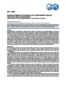
Propagation and attenuation of elastic waves in fluid-saturated rocks can be understood as a true multi-scale problem. Altogether, one may distinguish between three relevant spatial length scales being called macro-, meso- and micro-scale, see Fig. 1.1. Hereby, the macro-scale represents the observable length scale, where the wave propagation takes place. The macro-scale is characterized by rather smooth heterogeneities with a large wave-length. Typically, the macro-level is associated to a length scale of the order of magnitude L > 100 m. The small end of the length scale is defined by the heterogeneous micro-level being defined as the scale of discrete grains and pore channels at λ ∼ 1 mm. A third length scale has to be taken into account if there exist additional heterogeneities at an intermediate length scale significantly larger than the pore scale but smaller than the wave-length of the macroscopic mechanical stimulation (λ ≪ l ≪ L). Typically, the characteristic length of the meso-level is of the order of magnitude l ∼ 1 m.
e�e tive geologi al model (ma ro-s ale)
dis rete grain s ale (mi ro-s ale)
PSfrag repla ements
solid grains ϕs pore �uid ϕf L
λ
poroelasti ba kground fra ture network l
poroelasti meso-s ale
Figure 1.1: The fluid-saturated porous medium in a multi-scale representation.
In literature, attenuation of elastic waves observed in such fluid-saturated rocks is explained by the viscous redistribution of pore fluid taking place at different length scales. Mavko and Nur [87] proposed the squirt flow model, see also [36, 86]. Here, the elastic waves propagating through the fluid-saturated rock are considered to induce pressure gradients in the pore space and, therefore, to squeeze out pore fluid from micro-cracks into neighboring pores or cracks. Due to the viscous properties of this fluid transport process, part of the wave energy is lost, and the mechanical wave is attenuated. Since mass exchange occurs only between cracks or pores and their direct neighbors, the corresponding
1.1. Seismic attenuation: The physical phenomenon
3
fluid transport processes exhibit a rather short (microscopic) range and, consequently, squirt flow phenomena are active at relatively high frequencies (f > 1000 Hz). Further relevant attenuation mechanisms are active at seismic frequencies (0 < f < 100 Hz), where wave-induced fluid flow is caused by fluid pressure gradients between mesoscopic heterogeneities. Hereby, the heterogeneities may be represented by spatially varying properties of the rock matrix as well as of the saturating pore fluid. We, therefore, distinguish between the double porosity model proposed by Pride and Berryman [100] and the patchy saturation model first introduced by White [140, 141]. In the case of double porosity, the solid rock skeleton is supposed to consist of several spatially distributed porous phases and, at the same time, to be saturated by one single pore fluid. The different solid phases may result from heterogeneously consolidated layers building the rock. Alternatively, mesoscopic fractures and joints might coexist with a homogeneous porous rock. By contrast, the patchy saturation defines a rock with homogeneous material properties of the solid skeleton, which is heterogeneously saturated by several pore fluids. In both cases, mechanical waves propagating through such a heterogeneous medium lead to a reduced pore space depending on the solid frame stiffness or the fluid compressibility and induce mesoscopic pressure gradients between regions with varying material properties. The pressure gradients are equilibrated by a redistribution of the viscous pore fluid and cause pore pressure diffusion. Hereby, part of the wave energy is lost and the wave is attenuated at seismic frequencies. This causal relationship between mesoscopic heterogeneities, pore pressure diffusion and seismic attenuation has been recently verified by analytical, numerical and experimental investigations, see, for example, [75, 94, 97, 101, 127]. Hereby, it has been shown that the heterogeneous meso-scale can be successfully modeled by poroelastic formulations based on the work of Biot [7, 8]. From the observer’s viewpoint, only the effective attenuation of the propagating waves is detectable. All the underlying processes, however, are completely hidden and take place on a scale much smaller than the macro-scale. Consequently, the fluid flow or, respectively, the pore pressure diffusion is considered as a local phenomenon. In other words, the mesoscopic diffusion length is much smaller than the macroscopic wave-length. Under these circumstances, the overall medium can be understood as a homogeneous singlephasic (Cauchy) continuum accounting for appropriate viscoelastic dissipation mechanisms. However, the identification of the particular material properties of the macroscopic substitute medium is not a trivial task. This becomes clear if we consider White’s model for a 1D layered medium with patchy pore fluid saturation, see Fig. 1.2 a). Applying macroscopic strains or stresses on such a medium in terms of a step function results in a time-dependent material response featuring a stress-relaxation or, respectively, a creeping behavior. In frequency domain, the attenuation of the effective stiffness coefficient leads to the well-known properties depicted in Fig. 1.2 b). Hereby, the attenuation is quantified using the inverse quality factor Q1 , which is equivalent to the tangent of the phase angle. The White model yields an attenuation proportional to the frequency f in the low-frequency limit and proportional to √1f in the high-frequency limit. Hereby, the transition point is defined by the critical Biot frequency ωc = 2 π fc = ρfbα0 ∞ with the viscous damping parameter b0 , the partial fluid density ρf and the Biot parameter α∞ for
4
1. Introduction
f → ∞, see [74] for more information. However, comparing this result to the attenuation predicted by a (linear) three-parameter Maxwell-Zener substitute, we find that the attenuation of White’s model can, a priori, not be described by this simple viscoelastic model. Thus, more sophisticated substitute models are required even for this 1D case, which could be derived from mesostructural numerical simulations. To this end, Dutta and Od´e
3P model E0 σ
E1
fc
η1
σ log10 1/Q [–]
Sfrag repla ements
White model saturation gas water water σ
a)
White model √ ∝ 1/ f ∝f
∝ 1/f
3P model
σ
b)
log10 f [s−1 ]
Figure 1.2: a) Schematic plot of the viscoelastic 3-parameter (3P) model and White’s model for patchy saturated layered media, see [140]. b) Frequency dependence of the loss factor 1/Q for the 3P and White’s model. For frequencies larger than transition frequency fc the plotted curves are proportional to f1 (3P) and √1f (White).
[33, 34] proposed to use the dynamic Biot equations [9] with spatially varying material parameters to model poroelastic problems with patchy saturation. However, Carcione et al. [21, 19, 20] showed that the fully resolved simulation of wave propagation at low seismic frequencies is numerically inefficient due to the multiple temporal and spatial scales and is, therefore, restricted to artificially small control volumina. By contrast, several authors [82, 110] proposed to solve poroelastic initial value problems. They compute the effective material properties of the viscoelastic substitutes from volume averages of the mesoscopic quantities. Numerical efforts undergo additional reductions if Biot’s equation of (linear) consolidation neglecting inertia effects [6] are used for the description of the mesoscopic poroelasticity model [102, 103, 104, 139]. The presumption that inertia effects can be ignored is justified by the fact that, at low seismic frequencies, the inertia forces observed in fluid-saturated porous rocks during numerical simulation are much smaller than the forces associated with the elastic properties of the rock matrix and the viscous drag forces due to the fluid redistribution. As a consequence, it is possible to numerically investigate the attenuation properties of porous rocks solving transient boundary value problems such as stress relaxation (consolidation) or creeping experiments.
1.2. Computational homogenization
1.2
5
Identifying macroscopic substitute models by computational homogenization
The increasing need for a deeper understanding of microstructural processes and for the development of micro-tailored materials, in particular in the field of materials science, has stimulated a vivid evolution of scale-bridging techniques during the past decades. Something, they all have in common, is that homogenization techniques seek to derive the macroscopic material response based on simulations of the small-scale properties within a control volume with microstructural resolution. Hereby, the control volume has to be chosen large enough for being representative for the entire structure. One well-established homogenization technique being able to involve spatially distributed meso- or microscopic properties is the rigorous mathematical homogenization method, which represents a powerful tool to find coarse-grained solutions for idealized periodic structures. The idea of mathematical homogenization is based on the perturbation and asymptotic theory of partial differential equations and is, therefore, restricted to a geometrically as well as materially linear material behavior, see [1, 3, 5, 114]. We are, however, interested in the numerical modeling of seismic attenuation, which is caused by diffusive fluid transport and redistribution processes between mesoscopic heterogeneities in the poroelastic medium. Moreover, the aimed effective substitute model exhibits apparent viscoelastic properties. Hence, it is essential for the related upscaling problem to include at least material nonlinearities of the mesoscopic mixture and the macroscopic substitute medium. We, therefore, focus on the so-called computational homogenization procedure to accomplish the desired scale transition. The concept of (classical) computational homogenization is well-established in literature, and numerous contributions deal with various applications, see, for example, D¨ uster and Rank [59, 118, 32], Fish [42], Geers and Kouznetsova [51, 71, 72, 73], Huet [62], J¨anicke, Diebels, Steeb and coworkers [63, 66, 67, 117, 128], Larsson and Runesson [78, 76, 77], Michel [88], Miehe [91, 92], Schr¨oder, Balzani and coworkers [4, 116], Steinmann and Mergheim [41, 68], Wriggers and Temizer [124, 125], to name only a few. A comprehensive methodological overview including numerical aspects can be found in [79, 96, 145]. Hereby, Feyel and Chaboche [40] have coined the name FE2 for the numerical solution concept. The idea behind this concept is that kinematic or stress quantities observed at the macroscopic material/integration point are projected to the boundary of a mesoscopic control volume. The resulting boundary value problem can be solved numerically and the stress or, respectively, strain response is homogenized and transferred back to the macrolevel, where it can be used to compute the (tangent) stiffness or, respectively, compliance of the macroscopic substitute medium. This procedure requires the nested solution of one macroscopic and numerous fully-resolved mesoscopic boundary value problems in each individual iteration step. The solution of the mesoscopic boundary value problem replaces, therefore, the unknown macroscopic constitutive relation. However, even using rather small SVE sizes, leads, in particular in materially nonlinear 3D applications, to very high computational costs.
6
1. Introduction
This unsatisfactory situation provoked the development of several reduced order modeling techniques. The transformation field analysis (TFA) [35] and the closely related nonuniform transformation field analysis (NTFA) [89, 90, 108], dedicated to the homogenization of plastic and viscoplastic composites, approximate the inelastic strain fields on the small scale by a finite number of spatial inelastic modes. The variables controlling the evolution of these inelastic modes are considered as the internal variables of the macroscopic model. Fritzen and B¨ohlke [46, 48, 49] extended the NTFA concept by an energetically consistent derivation of the related evolution equations and opened the method to the class of generalized standard materials (GSM). With the hyper reduction technique [112, 113] and the proper generalized decomposition [25], further order-reduction methods are wellestablished in literature. All these approaches make use of the fact that, for numerous applications, the superposition principle can be applied. This is in particular valid for the GSM with material nonlinearities in a geometrically linear setup. Hereby, the superposition principle allows for an additive decomposition of the involved physical fields into elastic and, if necessary, numerous inelastic contributions. The main idea of order reduction is to precompute the material response on the small scale depending on the process and on the internal variables separately in the form of offline precomputations and to superimpose the accordingly weighted responses. Hence, the method yields a semi-analytic effective constitutive relations and the online computation on the large scale is restricted to solve the macroscopic boundary value problem under usage of the precomputed results. Compared to the nested FE2 computation technique this leads to significant numerical savings and makes it possible to address relevant technical applications. In this contribution, we aim to merge the introduced modeling techniques and to extend them towards a numerically efficient computational homogenization method for fluidsaturated porous media. In particular it is our interest to identify the appropriate viscoelastic substitute models for pressure diffusion in poroelastic and fractured media. To this end, the classical scale-bridging concepts as well as the order reduction concepts available in literature need significant generalization. We, therefore, divide this contribution into several thematic sub-problems and start our considerations in Chap. 2 by a review over the foundations and basic concepts of the Theory of Porous Media and their specifications in the case of a biphasic mixture consisting of a porous solid skeleton and a saturating (effective) pore fluid. Hereby, special regard is paid to the quasi-static formulation of poroelasticity. Subsequently, the fundamental concepts of classical computational homogenization are recalled. Chap. 3 is dedicated to the exploration of macroscopic viscoelastic substitute models for poroelastic media with spatially varying material properties on the meso-level. Hereby, we include cases with double porosity, patchy saturation as well as combinations of both. The particular difficulty of this upscaling problem lies in the fact that not all mesoscopic field quantities own an one-by-one representation in the viscoelastic substitute model. The homogenization is, therefore, called selective. To this end, we introduce in Sec. 3.1 a proper volume averaging concept based on an accordingly extended version of Hill’s principle of macro-homogeneity. This allows us to derive a set of consistent boundary conditions for the participating field quantities. The consequences of choosing different
1.2. Computational homogenization
7
boundary conditions are investigated in a first numerical study in Sec. 3.2. After having established the computational homogenization framework, Sec. 3.3 seeks to derive the material properties of the macroscopic substitute medium by a novel order reduction concept for the poro-to-viscoelastic upscaling problem. To this end, it is demonstrated how to derive the viscoelastic internal variables required for the solution of the large scale problem from a finite-dimensional set of pressure modes. The relation to standard viscoelastic rheologies is discussed. After all, the resulting new homogenization method is implemented and applied for numerical studies featuring the 1D White model in Sec. 3.4 and a 2D patchy saturation example in Sec. 3.5. Hereby, we find excellent agreements of the reduced order models with reference computations under various loading scenarios and requiring a reasonably low number of internal variables for the macro-scale formulation. The chapter is completed by the preliminary conclusions given in Sec. 3.6. Chap. 4 aims to sharpen our understanding for attenuation caused by waved-induced fluid flow and, consequently, pore pressure diffusion in mesoscopic fractures and joints. We, therefore, modify our modeling approach in Sec. 4.1 and consider spatially distributed mixtures of elastic and poroelastic constituents on the meso-level. Hereby, the elastic volume fractions are the model representations for crystalline and, therewith, impermeable rocks. The poroelastic inclusions exhibit passably high aspect ratios, high hydraulic permeability and low elastic (solid) stiffness and stand for hydraulically open and mechanically partly closed fractures. After having established the appropriately modified order reduction concept, we numerically investigate the resulting homogenization concept in Sec. 4.2 for a simple fracture network and validate it successfully in comparison to reference computations with full mesoscopic resolution. However, we can show that the poroelastic modeling of the fracture space suffers from several deficiencies. First, the choice of the poroelastic material parameters is not obvious and seems to be rather heuristic. Thus, this model allows for qualitative investigations, only. Second, the numerical efforts to mesh the fracture tips and to solve the resulting equation system restricts the applicable aspect ratios to unacceptably law values. Consequently, we seek for a more efficient modeling approach for the diffusion processes being active in the fractures. To this end, we derive in Sec. 4.3 a dimensionally reduced formulation for the fracture diffusion. Hereby, the individual fractures are considered as planar topologies in a 3D control volume. We allow for pressure diffusion in the individual fractures, mass exchange between the fractures, mass exchange between the fractures and the surrounding rock matrix (leak-off) and, last but not least, pore pressure diffusion in the fluid-saturated porous rock matrix. An adapted version of the order reduction formalism is developed and, interestingly, does not change the structure of the evolution laws in the macro-model. The hybrid-dimensional homogenization concept is successfully validated in Sec. 4.4, whereas Sec. 4.5 recapitulates the key findings and physical interpretations of the observed phenomena. Chap. 5 is dedicated to a rather fundamental extension of the physical processes under investigation. Whereas, so far, the diffusion processes causing the effective viscosity have been restricted to proceed inside the control volume, we now include explicit macroscopic stimulations of the mesoscopic diffusion problem in our concept. In other words, we allow
8
1. Introduction
for macroscopic fluid transport processes. We call the resulting substitute material a poroviscoelastic medium. Hereby, we introduce a volume averaging concept based on an affine macroscopic stimulation of the mesoscopic pore pressure field in Sec. 5.1. Again, an appropriately extended version of Hill’s principle of macro-homogeneity is the center point of our derivations. In Sec. 5.2, the computational homogenization concept is completed by a novel poroviscoelastic version of the reduced order modeling concept. Sec. 5.3 raises some drawbacks of the proposed method. In particular, it can be shown that the derived set of mesoscopic boundary conditions is closely related to the Voigt limit in classical computational homogenization. This motivates us to propose an alternative poro-toporoviscoelastic upscaling approach based on a flux control of the meso-scale problem in Sec. 5.4. We modify the averaging concept accordingly and derive the corresponding order reduction formalism in Sec. 5.5. We show that the structure of the equations controlling the temporal evolution of the macroscopic internal variables remains unchanged compared to the poro-to-viscoelastic problem. However, additional stimulations of the internal variables are provided in terms of the additional macroscopic process variables. We show, moreover, that the derived boundary conditions correspond to the Reuss limit in classical homogenization. The fascinating properties of the different loading scenarios are under investigation in Sec. 5.6. Hereby, we focus on the interesting case of a control volume incorporating a diffusion barrier. We study in detail the activated physical processes and discuss physical interpretations for our observations. The chapter is summed up in the preliminary conclusions given in Sec. 5.7. The present work closes with an overarching recapitulation and discussion of the investigated phenomena and the key finding in Chap. 6. It includes an outlook on future challenges and opening research fields. For the sake of an efficient numerical implementation the algorithmic tangent operators for the proposed viscoelastic constitutive relations are derived in the Appendix of this contribution.
1.3
Notation
Throughout this work we use a tensor notation closely related to the system proposed by de Boer [12]. Generally, vectors and tensors are written as bold characters. Hereby, we restrict our considerations to the orthonormal vector basis E = {e1 , e2 , . . . , en } in the n-dimensional Euclidean vector space En defining the Cartesian coordinates. Accordingly, second and higher rank tensors are written as A2 = Aij ei ⊗ ej , A3 = Aijk ei ⊗ ej ⊗ ek , etc. Hereby, Einstein’s sum convention is considered for indices appearing twice within one product. We use for the inner vector and tensor products the contractions A·b = Aij bj ei , A : B = Aij Bij , etc. The second rank identity tensor is defined as I = δij ei ⊗ ej with the Kronecker symbol δij . Particular regard has to be paid on the notation for the multi-scale problems. Hereby, the quantity ¯⋄ represents the macroscopic counterpart of the mesoscopic quantity ⋄ with the
1.3. Notation
9
identical physical interpretation and the same dimensions. The notation related to the multi-phase aspects of this work is introduced at appropriate points within the subsequent chapters. For the sake of a clear presentation, we do not display coordinate systems throughout all numerical studies and plots. We assume, once for all, Cartesian coordinates with the positive x1 -direction pointing to the right and the positive x2 -directions pointing upwards.
2 Theoretical foundations
After having introduced the general framework and the goals of this work, the following section is dedicated to recall the fundamental modeling and upscaling techniques used for the multi-phase and multi-scale problems under investigation. As we have seen above, we distinguish between three relevant length scales, see Fig. 1.1. Hence, we need to accomplish two upscaling steps, first, the micro-to-meso transition and, second, the mesoto-macro transition. However, both upscaling steps require an individual treatment. This is a consequence of the different physical processes being active at the different length scales. In particular, the amount of structural information that needs to be transported from the particular small to the next larger scale deviates drastically. This issue has to be discussed in more detail. Therefore, it is important to recall that, throughout this work, we are interested in rather slow processes. The wave length of the macroscopic mechanical loading processes is significantly larger than the typical length scale of the meso-level, and it is much larger than the typical length scale of the micro-level. Moreover, the pressure diffusion mechanisms, which are in the focus of this contribution, take place on mesoscopic length scales much larger than the microscopic ones. The mesoscopic material points are, therefore, associated with microscopic Representative Volume Elements (RVE) with a quasi-homogeneous, smeared-out structure. The morphology of the micro-level (for example the spatial distribution of the constituents existing on the microscopic length scale) is hidden for the diffusion processes under investigation. The mesoscopic material behaviour is dictated by the volume fractions of the participating constituent phases (solids, fluids), only. We, therefore, use the Theory of Porous Media (TPM) to derive the mesoscopic material model in terms of effective mesoscopic material parameters taking into account the micro-structural properties in an averaged manner. On the meso-level, the prevalent heterogeneities induce pressure diffusion processes lead-
– 11 –
12
2. Theoretical foundations
ing to a redistribution of the pore fluid inside a mesoscopic RVE. Hereby, the spatial distribution of the heterogeneities (varying saturating fluids or rock matrix properties) plays an important role, and the mesoscopic volume fraction of the involved materials is insufficient for a precise macroscopic substitute model. We, therefore, develop an adopted computational homogenization technique to describe the meso-to-macro transition. In the sequel, we recall the theoretical foundations and relevant techniques for both upscaling approaches.
2.1
Theory of Porous Media
We start our theoretical considerations by a recapitulation of the Theory of Porous Media (TPM). The TPM can be understood as a straight-forward extension of the classical Mixture Theory (MT), see [16, 129, 130]. This well-established theory assumes heterogeneously composed continua consisting of an arbitrary number of miscible and interacting constituents. In contrast to a microscopic description of such multi-phase media, the various interactions between the constituents are resolved on an effective, in our case mesoscopic, length scale rather than on a microstrucutral level. Hence, the microscopic or even intermolecular interaction processes are not explicitly considered but enter a phenomenological description on a larger length scale. It is important to remark that the MT, therefore, does not involve any microscopic information. Moreover, it supposes perfectly miscible mixtures. Investigating the effective properties of a fluid-saturated porous material consisting of, at least, one solid and one fluid constituent, the miscibility is, obviously, not satisfied [17, 142]. The MT has, therefore, been enriched by the volume fractions of the participating phases, resulting in the TPM, see, for example, [13, 14, 29, 37, 38] and citations therein. In the sequel, we follow the argumentation and derivations of the TPM as presented by Diebels [29], Ehlers [38] and Steeb [121]. Further information concerning the operations in analogy to standard continuum mechanics can be found, for example, in [56, 81].
2.1.1
The concept of volume fractions
We consider a mixture ϕ consisting of k constituents ϕα , α = 1, 2, . . . , k. The TPM bases on the fundamental assumption that all constituents of a mixture are statistically distributed within the control volume under consideration. The mixture itself behaves like a usual single phase material whose material properties are computed as the superposition of the interacting continua ϕα . We write ϕ =
k [
α=1
ϕα .
(2.1)
2.1. Theory of Porous Media
13
In other words, all constituents ϕα exist simultaneously at all material points of the superimposed continuum included in the (mesoscopic) homogenized control volume V , see Fig. 2.1. Hereby, the total volume V occupied by the mixture computes as V =
Z
dv =
k X
α
V , with V
α
=
α=1
V
Z
dv
α
=:
V
Z
nα dv.
(2.2)
V
The V α are called the partial volumes of the constituent ϕα , α = 1, 2, . . . , k. The concept PSfrag repla ements
mi ro-s ale
homogenized model
volume fra tions
ϕs
dv f
dv
ϕf
dv s
homogenization
simpli� ation of the mi romorphology
Figure 2.1: Homogenization of a discrete micro-scale model towards a smeared-out, homogenized meso-scale model using the TPM. Here, the example of a biphasic medium is shown with one solid phase ϕs and one fluid phase ϕf .
of volume fractions states that no information about the micro-morphology besides the volume fractions of the particular constituents is considered. In particular, the spatial distribution of the constituents is completely ignored. The concept of volume fractions, therefore, represents a simplified “microstructure” model, see Fig. 2.1. Hereby, the volume fraction of the constituent ϕα is computed as the ratio of the partial volume element dv α and the total volume element dv, nα =
dv α . dv
(2.3)
In accordance with Eq. (2.2)1 , the saturation condition can be introduced as k X
nα = 1.
(2.4)
α=1
In an analogous manner, we can define the total mass M of the mixture as the sum of the partial masses M α of the constituents ϕα . We write M =
Z
V
dm =
k X α=1
α
M , with M
α
=
Z
V
dmα .
(2.5)
14
2. Theoretical foundations
The above relations allow for the introduction of two different definitions for the density. In the TPM, one distinguishes between the effective (true) density ραR and the partial density ρα , α = 1, 2, . . . , k, given as ραR =
dmα , dv α
ρα :=
dmα . dv
(2.6)
The partial mass elements dmα compute, accordingly, as dmα = ραR dv α = ρα dv.
(2.7)
Hence, we can derive the relation between the density functions ρα = nα ραR .
(2.8)
In the case of a liquid S phase ϕl representing a mixture of several constituents ϕβ , β = l 2, 3 . . . , k, where ϕ = kβ=2 ϕβ and ϕ = ϕs ∪ ϕl , the volume fractions may be substituted by the saturation functions sβ of the k − 1 miscible pore fluids ϕβ , s
β
k X nβ l := l , with n = nβ . n
(2.9)
β=2
Hereby, it holds that sβ ∈ [0; 1] under the constraint k X
sβ = 1.
(2.10)
β=2
From a physical point of view, nβ quantifies the volume fraction of the phase ϕβ related to the control volume V , sβ the volume fraction of phase ϕβ related to the total pore space V l . It is, therefore, convenient, to rename the volume fraction of the pore space as the porosity φ computed as l
φ := n
=
k X
nβ .
(2.11)
β=2
2.1.2
Kinematics in the Theory of Porous Media
The TPM describes mixtures as superimposed continua. Considering a material point P in the current configuration at the time t > t0 , the material point is simultaneously occupied by all constituents ϕα , α = 1, 2, . . . , k. However, each constituent follows its individual motion function χα , see Fig. 2.2. In other words, the reference positions of the material particles P α occupying P in the current configuration are not necessarily identical. In
PSfrag repla ements 2.1. Theory of Porous Media
15
urrent on�guration t1 > t0
referen e on�guration
future on�guration
t0
t2 > t1
χs P
Ps
Pβ
Pβ
Ps
χβ x
Xs Xβ
O
Figure 2.2: Motion functions of a superimposed biphasic medium.
general, the different phases proceed from individual reference points. Analogously, their future positions will be, in general, individual for each phase ϕα . The motion function of phase ϕα is, therefore, defined as x = χα (Xα , t),
α = 1, 2, . . . , k.
(2.12)
The motion function χα maps the position vector Xα uniquely onto the current position vector x. The motion function is invertible and, therefore, each material point in the current position can only be occupied by exactly one single material particle P α of each constituent ϕα . The invertibility requires a non-singular Jacobian determinant Jα of phase ϕα with Jα = det
∂χα 6= 0. ∂Xα
(2.13)
The inverse motion function follows as Xα = χ−1 α (x, t).
(2.14)
Hereby, Eq. (2.12) represents, in analogy to standard continuum mechanics, the Lagrangean (material) description of the motion, whereas Eq. (2.14) refers to the Eulerian (spatial) description. Since all constituents follow their own unique motion function, the constituents have individual velocity and acceleration fields, too. In the material description, we can write vα := x˙ α =
∂ 2 χα (Xα , t) ∂χα (Xα , t) ¨α = and aα := x . ∂t ∂t2
Hereby, the dot symbol is used for the partial time derivative ⋄˙ =
∂⋄ . ∂t
(2.15)
In the spatial
16
2. Theoretical foundations
description, it follows with the usual argumentation x′α = x′α (x, t) and x′′α = x′′α (x, t),
(2.16)
with the material time derivative (⋄)′α referring to the motion of ϕα defined as (⋄)′α = ⋄˙ + (⋄ ⊗ ∇x ) · vα ,
(2.17)
which holds for any sufficiently regular and differentiable function ⋄(x, t). Here, we use the ∂ gradient operator ∇x with respect to the current position x, which is defined as ∇x = ∂x . Analogously, the (barycentric) velocity v of the mixture can be defined introduced as v := x′ =
with the definition of the mixture density ρ =
k 1 X α ρ vα , ρ α=1 k P
(2.18)
ρα . The material time derivative of the
α=1
mixture is given by
⋄′ = ⋄˙ + (⋄ ⊗ ∇x ) · v.
(2.19)
Hence, the two material time derivatives (⋄)′α and ⋄′ differ in the velocity associated to the particular convective contribution. Finally, we introduce the solid displacement us = x − Xs
(2.20)
and the seepage velocities of the individual fluid phases ϕβ , for β = 2, 3, . . . , k, wβ = x′β − x′s .
(2.21)
In other words, a Lagrangean description is used for the motion of the solid matrix ϕs , the motion of the fluid constituent ϕβ is formulated in a modified Euelerian (spatial) description. If one computes the derivation of the motion function χα with respect to the reference position vector Xα of the phase ϕα , one obtains the partial deformation gradient Fα =
∂χα (Xα , t) := χα ⊗ ∇Xα = x ⊗ ∇Xα . ∂Xα
(2.22)
Hereby, the material gradient operator ∇Xα represents the derivative with respect to the reference position Xα , α = 1, 2, . . . , k. The inverse deformation gradient F−1 α is α computed as the derivative of the inverse motion function of the phase ϕ with respect
2.1. Theory of Porous Media
17
to the position vector of the current configuration F−1 = α
∂χ−1 α (x, t) = χ−1 α ⊗ ∇x = Xα ⊗ ∇x . ∂x
(2.23)
From Eqs. (2.22) and (2.23) it becomes clear that the deformation gradient Fα refers to the material description, whereas the inverse deformation gradient F−1 α is used for the spatial description. In the undeformed state, the deformation gradients satisfy the condition Fα = F−1 α = I. The invertibility of the deformation gradient requires a strictly positive Jacobian determinant, for α = 1, 2, . . . , k, det Fα = Jα > 0
(2.24)
The deformation gradients can be related to the material and spatial displacement gradients by = I − uα ⊗ ∇x . Fα = I + uα ⊗ ∇Xα and F−1 α
(2.25)
From a physical point of view, the deformation gradient Fα transports line elements dXα of the reference configuration onto line elements dx of the current configuration by the linear mapping dx = Fα · dXα .
(2.26)
Vice versa, the inverse mapping reads dXα = F−1 α · dx.
(2.27)
Both mapping procedures contain stretch and rotation contributions. Indeed, the deformation gradient may undergo an unique polar decomposition into a proper orthogonal rotation tensor Rα and a symmetric and positive definite stretch tensor Uα or, respectively, Vα . We write Fα = Rα · Uα = Vα · Rα .
(2.28)
Further deformation tensors can be derived analyzing the transport properties of squares of line elements. Hence, the relation ds2 = dx · dx = dXα · FTα · Fα · dXα = dXα · Cα · dXα
(2.29)
leads to the definition of the partial right Cauchy-Green deformation tensor Cα = FTα · Fα
(2.30)
of the phase ϕα , α = 1, 2, . . . , k. Vice versa, the relation −1 −1 dSα2 = dXα · dXα = dx · F−T α · Fα · dx = dx · Bα · dx
(2.31)
18
2. Theoretical foundations
defines the partial left Cauchy-Green deformation tensor Bα = Fα · FTα
(2.32)
of the phase ϕα , α = 1, 2, . . . , k. Whereas the Cauchy-Green deformation tensors result in the identity tensor I in the undeformed state, we can derive the partial strain tensors with the value 0 for the undeformed state by computing the differences of line elements square as ds2 − dSα2 = dx · dx − dXα · dXα = dXα · (Cα − I) · dXα = dx · (I − B−1 α ) · dx.
(2.33) (2.34)
The tensors Eα =
1 1 (Cα − I) and A = (I − B−1 α ) 2 2
(2.35)
are called the partial Green-Lagrange and, respectively, the partial Euler-Almansi strain tensor of the phase ϕα , α = 1, 2, . . . , k. In the geometrically linear case, the GreenLagrange strain tensor Eα reduces to the well-known engineering strain εα by εα = Elin α =
1 (uα ⊗ ∇ + ∇ ⊗ uα ). 2
(2.36)
In the geometrically linear case, we suppose the material and the spatial gradients to ∂⋄ . coincide and we use, therefore, the unified derivation symbol ∇⋄ = ∂x Finally, we would like to measure strain rates in terms of the partial strain rate tensor Lα defined as Lα := vα ⊗ ∇x = F′α · F−1 α .
(2.37)
By convenience, the strain rate tensor is additively split into its symmetric and its skewsymmetric part by ( Dα = 21 (Lα + LTα ), Lα = Dα + Wα with (2.38) Wα = 21 (Lα − LTα ).
2.1.3
Balance relations
The quantities introduced so far describe the motions and the deformations of the mixture as well as of its single constituents in a kinematic and, therefore, geometrical fashion. We now seek for the formulation of conservation laws which are, as it is the case for classical single-phase materials, motivated in an axiomatic manner. In the TPM, the analogon to
2.1. Theory of Porous Media
19
the classical conservation laws are the balance relations for the entire mixture. Moreover, the TPM introduces conservation laws for the various constituents ϕα and follows therein the axiomatic statements known as Truesdell’s metaphysical principles, see [129]. Thus, the balance relations for the mixture ϕ as well as those of the single constituents ϕα are supposed to show the structure of the balance relations of the classical single-phase material. The partial conservation laws for the single constituents are completed by appropriate interaction terms representing the various exchange mechanisms between the different phases. In the sequel, we discuss the different conservation laws in detail.
Mass balance The conservation of mass for the phase ϕα requires that the change of mass in time of this constituent equals the mass exchange with other phases. Hence, we can write ˆ α. (M α )′α = M
(2.39)
ˆ α are defined as The mass M α and the mass production M Z Z α α α ˆ = M = ρ dv and M ρˆα dv. V
(2.40)
V
Since the global mass balance, computed as the sum over the partial mass balances, requires the total mass content of the control volume V to be constant in time, it follows directly the constraint for the mass production k X
ˆ α = 0. M
(2.41)
α=1
Localization of this global mass balance expression leads to (ρα )′α + ρα ∇x · vα = ρˆα ⇔
ρ˙ α + ∇x · (ρα vα ) = ρˆα ,
(2.42) (2.43)
where the material time derivative has been evaluated. Moreover, we may substitute the partial mass density by ρα = nα ραR and the partial mass production by ρˆα = n ˆ α ραR resulting in (nα ραR )• + ∇x · (nα ραR vα ) = n ˆ α ραR .
(2.44)
The total mass balance of the mixture computes as the sum of the partial balance relations with the constraint that the mixture’s mass production vanishes. Hence, M ′ = 0.
(2.45)
20
2. Theoretical foundations
Localization of the balance law results in the form known for single-phase continua ρ′ + ρ ∇x · v = 0 ⇔ ρ˙ + ∇x · (ρ v) = 0.
(2.46)
The constraint for the mixture’s vanishing mass production is written as ρˆ =
k X
ρˆα = 0.
(2.47)
α=1
Momentum balance
The momentum balance states that the momentum L of a body changes by action of the external forces F. Following Truesdell’s axioms, the same relation must hold for the constituent ϕα including an appropriate momentum exchange term. Hence, we write the global form of the momentum balance of the phase ϕα , α = 1, 2, . . . , k, as ˆ α, (Lα )′α = Fα + S
(2.48)
ˆ α . The partial momentum Lα , the partial force vector with the momentum production S ˆ α are given by Fα and the momentum production S Z Z Z Z α α α α α α α ˆ = ˆsα dv, L = ρ vα , F = t da + ρ b dv, S (2.49) V
∂V
V
V
with the constraint k X
ˆ α = 0. S
(2.50)
α=1
In other words, the momentum production of the mixture vanishes. Hereby, the vector ˆsα is called the total momentum production of phase ϕα . As usual, the external forces are split into surface tractions tα and body forces ρα bα . The localization of Eq. (2.48) yields ˆ α. ρα aα = Tα · ∇x + ρα bα + p
(2.51)
Hereby, Reynold’s transport theorem, see [56], the Cauchy theorem tα = Tα · n with the partial Cauchy stress tensor Tα and the outwards surface normal vector n as well as the partial balance of mass Eq. (2.43) have been used. Moreover, the direct momentum ˆ α has been defined as exchange p ˆ α = ˆsα − ρˆα vα . p
(2.52)
2.1. Theory of Porous Media
21
The sum over the total momentum productions of all phases ϕα , α = 1, 2, . . . , k, must vanish and it holds k X
ˆsα = 0.
(2.53)
α=1
Hence, the momentum balance of the mixture can we written in local form as ρ a = T · ∇x + ρ b.
(2.54)
Balance of momentum moments Besides the momentum the momentum moments have to satisfy a conservation law: The rate of momentum moments Hα is balanced by the moment of the surface and body forces Mα acting on V . In the case of the partial balance law for the constituent ϕα , a production ˆ α , representing the momentum moment exchange between the particular phases, term H has to be introduced. We, therefore, write ˆ α. (Hα )′α = Mα + H
(2.55)
Here, the definitions H
α
=
Z
(x − x0 ) × ρα vα dv,
(2.56)
V α
M
=
Z
(x − x0 ) × t da +
Z
ˆ α dv h
α
∂V
ˆα = H
Z
(x − x0 ) × ρα bα dv,
(2.57)
V
(2.58)
V
are used. The position vector x0 describes an arbitrary but fixed reference point to compute the force moments. The momentum moment production of the mixture must vanish and, therefore, the constraint k X
ˆα = 0 H
(2.59)
α=1
has to be satisfied. Localization of the global conservation law Eq. (2.55) under usage of Reynold’s transport theorem and the mass balance Eq. (2.43) yields ˆ α. I × Tα = −m
(2.60)
22
2. Theoretical foundations
Hence, the partial Cauchy stresses Tα are only symmetric if the direct momentum exˆ α vanishes. The direct momentum exchange mα and the total momentum change m ˆ α are related by exchange h ˆ α − (x − x0 ) × (ˆ ˆα = h m pα + ρˆα vα ).
(2.61)
The momentum moment production of the mixture must vanish and, therefore, the constraint k X
ˆα = 0 h
(2.62)
α=1
has to be satisfied. The mixture’s balance of momentum moments, therefore, results in the symmetry condition of the total Cauchy stress tensor T, I × T = 0 ⇔ T = TT .
(2.63)
Energy balance
The conservation of energy states that the rate of the partial internal energy E α and the kinetic energy K α of the constituent ϕα stored in the control volume V are balanced by α the power of the partial external forces Pext , the partial thermal power Qα and the partial α energy production Eˆ . We write α (E α + K α )′α = Pext + Qα + Eˆ α
(2.64)
with E
α
=
Z
ρα ǫα dv,
(2.65)
V α
1 = 2
α Pext
Z
K
Z
ρα vα · vα dv,
(2.66)
V
=
α
t · vα da +
Z
q α da +
Z
eˆα dv.
V
(2.67)
Z
ρα r α dv,
(2.68)
V
∂V
ˆα = E
ρα bα · vα dv,
V
∂V
Qα =
Z
(2.69)
2.1. Theory of Porous Media
23
Hereby, we have introduced the partial specific internal energy ǫα , the partial heat flux over the surface q α , the partial radiation r α and the total energy production eˆα . As we have done for the conservation laws above, we execute the localization under usage of Reynold’s transport theorem and the lower balance relations. Moreover, we split the local energy balance into the balance of internal energy ρα (ǫα )′α = Tα : Lα − ∇x · qα + ρα r α + ǫˆα + ρˆα ǫα
(2.70)
and the balance of kinetic energy 1 α ρ (vα · vα )′α = (vα · Tα ) · ∇x − Tα : Lα + ρα bα · vα 2 � � 1 α α vα · vα . +ˆ p · vα + ρˆ 2
(2.71)
ˆ α, It is important to remark that, in absence of a momentum moment production m the partial Cauchy stress Tα becomes symmetric and that the strain rate Lα can be substituted by its symmetric contribution Dα in Eqs. (2.70) and (2.71). The direct energy production is computed as the difference of the total energy production and the lower production terms via � � 1 α α α α α ˆ · vα − ρˆ ǫ + vα · vα . (2.72) ǫˆ = eˆ − p 2 The total energy production must vanish. Hence, the constraint k X
eˆα = 0
(2.73)
α=1
has to be satisfied. The internal and kinetic energy balances of the mixture, therefore, read ρ ǫ′ = T : D − q · ∇x + ρ r,
1 ρ (v · v)′ = (v · T) · ∇x − T : D + ρ b · v. 2
(2.74) (2.75)
Entropy balance The set of balance relations is completed by the balance of entropy. The rate of the partial entropy Sˆα of the constituent ϕα is balanced by the entropy efflux and supply Rα and the entropy exchange in terms of the entropy production Sˆα . We write, (S α )′α = Rα + Sˆα ,
(2.76)
24
2. Theoretical foundations
where we use the definitions Z α S = ρα η α , dv,
R
α
=
V
Z
φαη
Z
ηˆα dv.
· n da +
σηα dv,
(2.77)
V
∂V
Sˆα =
Z
(2.78)
V
Hereby, σηα , φαη and ηˆα represent, respectively, the entropy supply, the entropy efflux and the total energy production. Localization of the global entropy balance yields ρα (η α )′α − ∇x · φαη − σηα = ζˆα ,
(2.79)
with the direct entropy production ζˆα . The total and the direct energy production are related via ζˆα = ηˆα − ρˆα η α .
(2.80)
The constraint on the total entropy production reads k X α=1
ηˆα ≥ 0.
(2.81)
The partial entropy outflux φαη as well as the partial entropy supply σηα can be specified as φαη = −
1 α 1 α α α q and σ = ρ r . η θα θα
(2.82)
Further discussions concerning the entropy principle can be found in [38]. The mixture’s local balance of entropy is given as � � 1 1 ′ q · ∇x − ρ r ≥ 0. ρη + θ θ
2.1.4
(2.83)
Master balance relations
Master balances of the mixture The conservation laws discussed above can be included in the system of Master balances in order to give a better overview over the various relations. In analogy to standard singlephasic materials in classical continuum mechanics, the Master balance of the mixture ϕ
2.1. Theory of Porous Media
25
in the global form is given as Z Z Z Z d ˆ dv, Ψ dv = φ · n da + σ dv + Ψ dt d dt
V
∂V
V
Z
Z
Z
Ψ dv =
V
Φ · n da +
V
σ dv +
V
∂V
(2.84)
Z
ˆ dv. Ψ
(2.85)
V
Hereby, the scalar- or vector-valued functions Ψ or, respectively, Ψ describe the volumespecific densities of the physical quantities to be balanced in V . The flux quantities acting on the surface ∂V are called φ · n and Φ · n. The supply terms are represented by σ and ˆ However, the production terms of ˆ and Ψ. σ, and, finally, we use the production terms Ψ the mixture are, usually, ignored. In other words, it is supposed that the interaction of the mixture with its environment takes place in terms of the surface fluxes or the volume supply. Localization of the global Master balances results in the local forms ˆ Ψ′ + Ψ ∇x · v = ∇x · φ + σ + Ψ,
(2.86)
ˆ Ψ′ + Ψ ∇x · v = Φ · ∇x + σ + Ψ.
(2.87)
The resulting balance laws can be found in compact form in Tab. 2.1. Ψ, Ψ
φ, Φ
σ, σ
ˆ ˆ Ψ Ψ,
ρ
0
0
0
ρv
T
ρb
0
(x − x0 ) × (ρ v)
(x − x0 ) × T
(x − x0 ) × ρ b
0
mass momentum momentum moment internal energy kinetic energy
ρǫ 1 ρv 2
entropy
·v
ρη
−q
0
v·T
ρ r + T : (v ⊗ ∇x )
ρ b · v − T : (v ⊗ ∇x )
0
φη
ση
ηˆ
Table 2.1: The mixture’s balance relations.
The partial Master balance The Master balances for the individual components ϕα of the mixture are introduced in an analogous manner. Hereby, the material time derivative is substituted by its partial
26
2. Theoretical foundations
counterpart evaluated in the direction of the partial velocity vα . Hence, we define Z Z Z Z dα α α α ˆ α dv, Ψ dv = ϕ · n da + σ dv + Ψ (2.88) dt dα dt
V
∂V
V
Z
Z
Z
α
Ψ dv =
V
α
Φ · n da +
V
α
σ dv +
V
∂V
Z
ˆ α dv. Ψ
(2.89)
V
Localization of these global equations yields the local Master balances ˆ α, (Ψα )′α + Ψα ∇x · vα = ∇x · φα + σ α + Ψ
ˆ α. (Ψα )′α + Ψα ∇x · vα = Φα · ∇x + σ α + Ψ
(2.90) (2.91)
The resulting partial balance laws can be found in Tab. 2.2.
Ψα , Ψ α
φα , Φ α
σα , σα
ˆ α, Ψ ˆα Ψ
ρα
0
0
ρˆα
ρα vα
Tα
ρα bα
ˆsα
(x − x0 ) × (ρα vα )
(x − x0 ) × Tα
(x − x0 ) × ρα bα
ˆα h
mass momentum mom. moments internal energy kinetic energy entropy
ρα ǫα
1 α ρ 2
vα · vα
ρα η α
−qα
vα · Tα φαη
ρα r α
+Tα : (vα ⊗ ∇x )
eˆαi
ρα bα · vα
eˆαk
σηα
ηˆα
−Tα : (vα ⊗ ∇x )
Table 2.2: The partial balance relations of the single constituents ϕα , α = 1, 2, . . . , k. Hereby, ˆ α · vα + ρˆα 12 vα · vα . eˆα = eˆαi + eˆαk , with eˆαi = ǫˆα + ρˆα ǫα and eˆαk = p
Hereby, the total production terms are computed as the sum of the direct production and contributions due to lower order productions. We can summarize as follows: ˆsα = p ˆ α + ρˆα vα ,
(2.92)
ˆα = m ˆ α + (x − x0 ) × (ˆ h pα + ρˆα vα ), � � 1 α α α α α ˆ · vα + ρˆ ε + vα · vα , eˆ = εˆ + p 2
(2.93)
ηˆα = ζˆα + ρˆα η α ,
(2.95)
(2.94)
2.2. Biphasic mixtures
27
with the saturation conditions k X
ρˆα = 0,
(2.96)
ˆsα = 0,
(2.97)
ˆ α = 0, h
(2.98)
eˆα = 0,
(2.99)
ηˆα ≥ 0.
(2.100)
α=1
k X α=1
k X α=1
k X α=1
k X α=1
The resulting system of partial differential equations has to be closed by the derivation of appropriate constitutive relations. Throughout this contribution, however, we restrict our considerations on a geometrically linear setting. Whereas we take into account materially nonlinear properties of the mixture, the mixture’s non-linearity results from the interaction of constituents with linear properties. The partial constitutive relations can be derived from standard quadratic potentials. For the sake of brevity, we, therefore, skip the further investigation of the constitutive modeling in the framework of the entropy principle. The interested reader is, for example, referred to [38].
2.2
Biphasic mixtures
Many applications in science and engineering deal with fluid-saturated porous media which consist of one solid constituent ϕs , representing the solid grains and the rock skeleton, and one fluid constituent ϕf , representing the pore fluid. Hereby, the pore fluid might be again a mixture of several miscible constituents. Throughout this work, we will restrict on these biphasic media. We, therefore, simplify the TPM settings as follows. First, the volume fraction occupied by the fluid phase can be computed as nf =
dv f dv
=: φ
(2.101)
and defines the porosity of th rock matrix φ(t), t > t0 , in the current configuration. If the effective pore fluid consists of two fluids, for example water and gas (α ∈ {w, g}), the
28
2. Theoretical foundations
fluid saturation, second, is given as sα =
dv α . dv f
(2.102)
The material parameters of the effective fluid can be, for example, computed using the averaging rules introduced by Wood [143] and Teja and Rice [123].
2.2.1
Biot’s equations of linear consolidation
In the sequel, we seek to rewrite the relevant balance equations and constitutive relations for the biphasic case. For the intended application to attenuation phenomena in the seismic frequency range, we restrict ourselves to the quasi-static case neglecting inertia forces and, moreover, body forces. Thus, the partial momentum balance Eq. (2.51) takes the form ˆ α = 0, Tα · ∇x + p
α ∈ {s, f }.
(2.103)
Neglecting mass production, that is ρˆα = 0, the saturation condition for the momentum production ˆsα Eq. (2.53) can be simplified as ˆss + ˆsf = p ˆs + p ˆ f = 0.
(2.104)
In other words, we exclude any phase transitions between solid and fluid phase. The balance equation for the mixture reduces to T · ∇x = 0
(2.105)
with the total Cauchy stress of the mixture T = Ts + Tf .
(2.106)
In the geometrically linear case, the material and the spatial gradient operator coincide and, therefore, the gradient operator used in Eqs. (2.103) and (2.105) can be simplified according to ∇x → ∇. Moreover, we replace the Cauchy stress tensors T, Tα by their counterparts σ, σ α . Hence, we rewrite Eq. (2.105) as σ · ∇ = 0 with σ = σ s + σ f .
(2.107)
In the sequel, Eq. (2.107) serves as the first Biot equation. We, therefore, introduce constitutive relations for the partial stresses σ s and σ f and follow the concept of effective stresses, first proposed by Terzaghi [126], and extensively discussed, for example, in [11, 15, 115, 120, 131]. Supposing linear elasticity, the partial solid and fluid stresses compute
2.2. Biphasic mixtures
29
as σ s = C : εs − α (1 − φ) p I,
(2.108)
σf =
(2.109)
σ = σs + σf =
− α φ p I, C : εs | {z }
=:σeff (εs (us ))
−α p I . | {z }
(2.110)
=:σ p (p)
Hereby, the effective stress σ eff is the part of the total stress that describes the stress response due to the deformation of the dry solid frame. We use the fourth rank elastic stiffness tensor C and the Biot parameter α to be specified in the sequel. In the case of an isotropic solid skeleton, the effective stress can be computed by means of the volumetricdeviatoric split of the solid strain tensor εs = εsph + εvol s s as σ eff = 2 G εdev + 3 K εsph s s ,
(2.111)
with the effective shear modulus G and the effective bulk modulus K of the dry skeleton. In addition to the effective stress, the total stress includes the contribution σ p due to the pore fluid pressure p. It is important to remark that, first, the pressure p is acting on the fluid phase ϕf as well as on the solid phase ϕs , see Eqs. (2.108) and (2.109), both weighted by their volume fraction φ or, respectively, (1 − φ). Second, the fluid pressure p can not be computed directly as a function of the solid phase displacement field us , but it represents an independent variable. We, therefore, have to consider a second equation coupled to the effective balance of momentum. In the sequel, this missing relation is derived, for numerical purposes, in the sense of a us -p formulation, see [144]. Hence, the pore pressure field p is treated as a second primary variable besides the solid displacement us . To this end, we investigate the partial balances of mass in order to describe the fluid motion relative to the skeleton. Any mass production ρˆα , α ∈ {s, f } is neglected, that is, phase transitions of the constituents are excluded and the partial masses of the two components contained in the control volume V are conserved. We write Z dα nα ρα R dv = 0, α ∈ {s, f }. (2.112) dt V
Taking into account dv = J dV , the time differentiation can be executed as Z � α αR ′ � (n ρ )α + nα ρα R ∇x · vα J dV = 0
(2.113)
V
⇔
Z V
�
� (nα ρα R )• + ∇x (nα ρα R ) · vα + nα ρα R ∇x · vα dv = 0,
(2.114)
where the material time derivative with respect to the motion of the phase ϕα has been
30
2. Theoretical foundations
evaluated. In localized form we find n˙ α ρα R + nα ρ˙ α R + ∇x (nα ρα R ) · vα +nα ρα R ∇x · vα = 0. | {z } convection
(2.115)
Our restriction to the geometrically linear case allows us to neglect the convection term in Eq. (2.115). Moreover, we use again the small strain representations ∇x = ∇ and Dα = ε˙ α = 12 (vα ⊗ ∇ + ∇ ⊗ vα ) for the partial deformation rate tensor. The fluid compressibility β f := 1/K f as well as the compressibility of the solid grains 1/K s are defined by the constitutive relations ρ˙ f R =
∂ρf R 1 fR p˙ = ρ p˙ ∂p Kf ρ˙ sR =
and
(2.116)
1 ρsR (−σ˙ − φ p), ˙ Ks 1 − φ
(2.117)
see, for example, Detournay and Cheng [28], Renner and Steeb [105], Verruijt [131, 132] or Wang [137]. Hereby, the volumetric part σ˙ of the total stress rate σ˙ is defined as σ˙ =
1 tr σ˙ = K ∇ · u˙ s − α p. ˙ n
(2.118)
Here, n represents the dimension of the problem. Taking into account nf = φ and ns = 1 − φ, the partial balances of mass can be rewritten as
−φ˙ −
φ φ˙ + f p˙ + φ ∇ · vf = 0, K
(α = f ),
(2.119)
1 φ σ˙ − s p˙ + (1 − φ) ∇ · u˙ s = 0, s K K
(α = s).
(2.120)
Finally, we combine Eqs. (2.119) and (2.120) and we find � � � � φ α−φ K p˙ = 0. + 1 − s ∇ · u˙ s + φ ∇ · wf + K Kf Ks {z } | {z } | =: α 1 =: M
(2.121)
This result allows us to define the Biot-Willis [10] parameters as α = 1−
K 1 φ α−φ and = + , s f K M K Ks
(2.122)
see also [50]. Thus, we can simplify and write the continuity equation in its final version as ∇ · (φ wf ) + Φ˙ = 0.
(2.123)
2.2. Biphasic mixtures
31
Hereby, we have introduced the storage function Φ representing the volume of fluid accumulated within an unit of bulk volume, Φ = φ + α ∇ · us +
1 p. M
(2.124)
In the geometrically linear case, the changes φ˙ in porosity during the time-dependent process are considered to be negligible and, therefore, the porosity is treated as a material parameter with φ(t > t0 ) = φ(t = 0) =: φ0 . In order to close the equation system we finally introduce a constitutive relation between the pore pressure gradient ∇ p and the filter velocity φ wf . Already in 1856, Henry Darcy found out by experimental evidence that the discharge of pore fluid through a fluidsaturated porous medium can be approximated by a linear dependency on the applied head loss [27]. In his honor, the resulting well-known relation is called Darcy equation and writes φ wf
ks = − f R ∇p. η
(2.125)
Hereby, we use the effective dynamic viscosity η f R of the effective pore fluid and the intrinsic permeability k s of the rock matrix. The intrinsic permeability can be assumed as a function of the pore space’s geometry, in particular of the porosity φ. For example, Carman and Kozeny [22] estimate the intrinsic permeability in a power law format depending on the porosity φ, k
s
φ3 . ∼ (1 − φ)2
(2.126)
By contrast, the intrinsic permeabilities used in the numerical experiments throughout this study originate from physical experiments available in literature for the materials under investigation. It is important to remark that the continuity equation (2.123) in combination with Darcy’s law Eq. (2.125) represents Biot’s second quasi-static equation of a (linear) consolidation process [6, 107]. From a physical viewpoint, this equation measures the amount of pore fluid expelled from a volume element due to an elastic compression of the rock matrix, the solid grains as well as the pore fluid itself. Moreover, it is important to notice that, depending on the material parameters and particularly depending on the intrinsic permeability k s , the pore pressure gradients may reach very high values even in the context of a linear consolidation process, whereas very low velocities for the relative motion of the pore fluid with respect to the solid matrix are observed. In other words, large pore pressure gradients result in the expulsion of a rather small mass of pore fluid. Hence, it is the phenomenon of pore pressure diffusion rather than the pore fluid transport that will be discussed in the sequel. Finally, we summarize the resulting coupled equation system for the quasi-static case
32
2. Theoretical foundations
of linear consolidation in strong format, with respect to the primary variables us and p which will be the basis for the studies on poroelasticity discussed in the following chapters. Thus, it holds σ(εs (us ), p) · ∇ = 0,
˙ s , p) = 0, ∇ · (φ wf (p)) + Φ(u
∀ x ∈ V,
(2.127)
∀ x ∈ V,
(2.128)
with Dirichlet and Neumann boundary conditions u us = u∗s ∀ x ∈ ∂D V, p p = p∗ ∀ x ∈ ∂D V,
u σ · n = t∗ ∀ x ∈ ∂N V,
(2.129)
p φ wf · n = q ∗ ∀ x ∈ ∂N V,
(2.130)
with the outwards surface normal vector n, the mass outflux q = φ wf · n and the surface traction t = σ · n related to the total stress tensor σ. The constitutive relations are summarized as σ =
C : εs −α p I, | {z } | {z }
(2.131)
=:σeff (εs ) =:σ p (p)
φ wf = −
ks ∇ p, ηf R
Φ = φ + α ∇ · us +
(2.132) p . M
(2.133)
All material parameters are specified in Table 2.3. ks φ G, K K s, K f K w, K g sw , sg ∈ [0, 1] ηf R η wR, η gR λ α M Kf ηf R sg
intrinsic permeability porosity (φ = φ0 ) elastic moduli of dry frame (shear, bulk) bulk modulus (solid grains, effective pore fluid) bulk modulus (water, gas) saturation (water, gas) effective dynamic viscosity (effective pore fluid) effective dynamic viscosity (water, gas) = K − 2 G/3 = 1 − K/K s = K f K s /(φ K s − (α − φ) K f ) = (K g K w )/(sg K w + sw K g ) w = η gR (η wR /η gR )s = 1 − sw
Table 2.3: Poroelastic material parameters and definitions. The effective fluid parameters K f and η f R are computed following the averaging rules in [143, 123], respectively.
2.3. Computational homogenization
2.2.2
33
Numerical solution
The numerical simulations throughout the following chapters are performed in the FE system COMSOL Multiphysics. To this end, the coupled equation system Eqs. (2.127) – (2.133) are transformed into their week format. The solid displacement us and the pore pressure p are treated as primary variables in a us -p formulation. Neglecting inertia forces, the remaining hydro-mechanically coupled diffusion problem is carried out in time domain. For more information, see, for example, [103]. The weak formats of the diffusion problems under discussion in this thesis will be introduced in the particular chapters. Alternatively, the poroelastic equation system can be evaluated in frequency domain. More details can be found in the original contributions of Biot [7, 8] or, for example, in [110].
2.3
Computational homogenization
As indicated above, it is insufficient for the second upscaling step from the meso- to the macro-scale model to restrict the homogenized structural information to the volume fractions of the coefficients. In fact, the spatial distribution of the heterogeneous properties plays a central role for the effective material properties on the large scale. We, therefore, apply an extended version of the computational homogenization procedure to accomplish the desired scale transition. We aim to recall the classical first-order computational homogenization technique for applications in single-phasic solid mechanics within this section. The standard approach will be, afterwards, extended towards the various upscaling problems under discussion in the following chapters. Throughout this work, the computational homogenization deals with the meso-to-macro transition. It is, nevertheless, important to remark that, in literature, the participating length scales are commonly called micro- and macro-scale. The homogenization rules are applied accordingly. The concept of computational homogenization supposes the perfect separation of the involved scales, in our case the macro- and the meso-scale. For practical applications, the condition of scale separation requires the characteristic macroscopic length scale L or, respectively, the wave length of the macroscopic loading to be (at least) much larger than the mesoscopic control volume and its characteristic length l, that is L ≫ l. It is the central idea of computational homogenization that macroscopic quantities ⋄¯ can be understood as their mesoscopic counterparts ⋄ averaged over the RVE volume V✷ . Hence, we introduce the volume averaging operator h⋄i✷ as Z 1 ¯⋄ := h⋄i✷ := ⋄ dv. (2.134) V✷ V✷
From a physical viewpoint, the above relation assigns the macroscopic material point to
34
2. Theoretical foundations
be the effective substitute of the mesoscopic RVE. In the sequel, we will derive appropriate homogenization rules in order to exchange information between the two scales.
2.3.1
The mesoscopic boundary value problem
If we are interested in a true two-scale simulation of a meso-heterogeneous material with the so-called FE2 -technique [40], we have to project kinematic or stress quantities computed at the macroscopic material/integration point to the boundary of the mesoscopic RVE occupying the volume V✷ , see Fig. 2.3. The resulting boundary value problem has to be solved numerically and the stress or, respectively, strain response is homogenized and transferred back on the macro-level, where it can be used to compute the (tangent) stiffness or, respectively, compliance of the macroscopic substitute medium. The particular projection and homogenization rules are based on appropriate model assumptions for the scale transition properties of selected quantities. ma ro-s ale B
¯ O ¯ x
PSfrag repla ements kinemati /stress loading lo alization
L x
V�
O
stru tural response homogenization l
meso-s ale
Figure 2.3: Meso-to-macro transition in the framework of computational homogenization.
Restricting ourselves to the kinematically linear case, the volume averaging concept is applied on the strain end stress fields in terms of Z 1 ¯ = hεi✷ = (u ⊗ n)sym da (2.135) ε V✷ ∂V✷
2.3. Computational homogenization
35
and ¯ = hσi✷ = h(x ⊗ ∇) · σi✷ σ
1 = V✷
Z
(x ⊗ t)sym da.
(2.136)
∂V✷
For the transformation from volume into surface integrals we use the Gauss integration rule. Moreover, the momentum balance of a single-phasic medium neglecting body and inertia forces, that is σ·∇ = 0, is inserted into Eq. (2.136). The execution of the averaging rules given above in terms of surface expressions is the key for the definition of consistent boundary conditions for the mesoscopic RVE problem. However, one further essential ingredient is required to formulate the mesoscopic boundary value problem, namely the equivalence of the macroscopic and the mesoscopic stress power. We write ¯ : ¯ε˙ = hσi✷ : hεi ˙ ✷ := hσ : εi ˙ ✷. σ
(2.137)
This relation is known as Hill’s principle of macro-homogeneity, see Hill [60, 61] and, for example, [54, 57, 84, 122]. For the derivation of the mesoscopic boundary value problem it is necessary to transform Eq. (2.137) into a surface expression and we find Z 1 ¯ : ¯ε˙ = u˙ · t da. (2.138) σ V✷ V✷
Here, we use again the Gauss integration rule and the momentum balance of the singlephasic and inertia-free Cauchy medium. The surface traction vector t = σ · n is defined in the usual way involving the outwards surface normal vector n. With this knowledge, we may derive different loading scenarios for the heterogeneous meso-scale model. First, evaluation of the macro-homogeneity condition Eq. (2.137) under the volume constraint Eq. (2.136)1 results in the uniform loading condition ¯·x u = ε
∀ x ∈ V✷ .
(2.139)
Hence, this condition prescribes a uniform mesoscopic strain for all material points in V✷ . ¯ can be In elasticity, it follows immediately that the overall macroscopic stiffness tensor C computed as ¯ = hCi . C ✷
(2.140)
This averaging property has been initially proposed by Voigt [136]. However, this condition is rather restrictive and, indeed, one can show that it leads to an upper bound for ¯ see [96]. Similarly, combining Eq. (2.137) and Eq. (2.135)1 yields the effective stiffness C, the condition ¯ σ = σ
∀ x ∈ V✷ .
(2.141)
Thus, this second condition predicts an uniform stress distribution and can be reformu-
36
2. Theoretical foundations
lated as ¯ = hSi . S ✷
(2.142)
¯ is computed as the volume average of its mesoscopic Hence, the effective compliance S counterpart. This finding is equivalent to the prediction introduced by Reuss [106]. Besides the fact that, again, this condition is very restrictive, it leads to incompatible deformations in heterogeneous media. However, it can be used as an upper bound for the effective compliance and, vice versa, as a lower bound for the effective stiffness. The strict conditions Eqs. (2.139) and (2.141) can be relaxed if the strain and stress fields are prescribed on the surface ∂V✷ , only. To this end we now use the surface versions of the stress and strain averaging rules. Thus, combining Eq. (2.138) with Eq. (2.136)2 results in the so-called Kinematic Uniform Boundary Condition (KUBC) ¯·x u = ε
∀ x ∈ ∂V✷ .
(2.143)
Analogously, the evaluation of Eq. (2.138) together with Eq. (2.135)2 yields the Stress Uniform Boundary Conditions (SUBC) ¯ ·n t = σ
∀ x ∈ ∂V✷ .
(2.144)
After the numerical solution of the resulting mesoscopic boundary value problems, the stress and strain averaging rules Eqs. (2.135)1 and (2.136)1 can be used again to homogenize the particular mesoscopic response required on the macro-level. We have supposed, so far, that the mesoscopic control volume V✷ represents a RVE. Hereby, the word “representative” means that the control volume is large enough to involve all relevant physical processes induced by the mesoscopic heterogeneities. In practical applications, however, the size of the mesoscopic volume element is limited by the available numerical power and, therefore, is generally smaller than the “true” RVE size. Following the terminology established in [99] the practically considered volume elements are called Statistical Volume Elements (SVE). The predicted overall properties are called apparent (SVE-based) instead of effective (RVE-based). However, the usage of SVE bears the problem that, due to their restricted size, the choice of the boundary conditions strongly influences the apparent properties of the substitute medium. Under these circumstances, the KUBC and the SUBC only allow for the definition of upper and lower bounds for the ¯ “true” effective properties.1 These over- and underestimations of the effective stiffness C can be interpreted as the consequence of stiff and, respectively, soft boundary layer effects due to the KUBC and the SUBC. Whereas the surface effects vanish for a true RVE with V✷ → ∞, significant fractions of a SVE volume are part of the boundary layer due to the external loading, see [58, 69]. Hence, further relaxation methods are required in order 1
However, the bounding properties are, obviously, more strict and, therefore, more useful as the Voigt and Reuss bounds. Further bounds have been defined, for example, by Hashin and Shtrikman [54, 55]. For more information, the interested reader is referred to [96].
2.3. Computational homogenization
37
to make the computational homogenization concept applicable for practical purposes. Throughout the following chapters, we make use of the well-established periodic boundary PSfrag where repla ements conditions, the affine displacement field on the surface ∂V✷ prescribed by Eq. (2.143) is superimposed by a periodic fluctuation. Here, we follow the notation presented in [76]. x− (3)
x+ (3)
x+ (2) x
− ∂V�
+ ∂V�
l x+ (1)
x− (1) V�
x− (3)
x− (2) l
Figure 2.4: RVE in 2D under meso-periodicity conditions with image boundary ∂V✷+ and mirror boundary ∂V✷− .
To this end, we split the boundary ∂V✷ into the image boundary ∂V✷+ and the mirror boundary ∂V✷− , see Fig. 2.4. Introducing the “jump operator” J✸K✷ (x) := ✸(x+ ) − ✸(x− )
∀x ∈ ∂V✷+
(2.145)
allows than to define the kinematically driven periodic boundary conditions as ¯ · JxK✷ , JuK✷ (x) = ε
(2.146)
t+ + t− = 0.
(2.147)
The above relations Eqs. (2.146) and (2.147) define the Periodic Boundary Conditions (PBC) involving periodic fluctuations and anti-periodic surface tractions. It is easy to prove that Eqs. (2.146) and (2.147) satisfy the macro-homogeneity condition Eq. (2.138). ¯, the homogenization loop is closed by means of the stress Prescribing the effective strain ε ¯ = hσi✷ . Finally, we are able to sum up the relevant KUBC, SUBC and averaging rule σ PBC in Tab. 2.4.
KUBC PBC SUBC
localization ¯·x u=ε ¯ · JxK✷ JuK✷ = ε t+ + t− = 0 ¯ ·n t=σ
∀ x ∈ ∂V✷ ∀ x ∈ ∂V✷+
homogenization ¯ = hσi✷ σ ¯ = hσi✷ σ
∀ x ∈ ∂V✷
¯ = hεi✷ ε
Table 2.4: Consistent boundary conditions for the standard first-order computational homogenization approach.
38
2. Theoretical foundations
We can now rewrite the mesoscopic boundary value problem in the standard variational format, see [111, 76]. Without loss of generality, we restrict the documentation of the homogenization problem in weak format to the case of PBC. Hence, we seek solutions in the trial space U✷ of admissible displacements that are sufficiently regular in V✷ . We, furthermore, introduce the corresponding trial space of self-equilibrated fluxes T✷ that are sufficiently regular on ∂V✷+ . We write the equations for finding u, t ∈ U✷ × T✷ as au (u, δu) − cu (t, δu) = 0,
(2.148)
¯ · x), −cu (δt, u) = −cu (δt, ε
(2.149)
which hold for any admissible test functions δu, δt ∈ U✷ × T✷ . We define au (u, δu) = hσ(ε(u)) : (δu ⊗ ∇)i✷ , Z 1 u c (t, u) = t · JuK✷ da, V✷
(2.150) (2.151)
∂V✷+
1 ¯ · x) = cu (t, ε V✷
Z
∂V✷+
¯. t ⊗ JxK✷ da : ε
(2.152)
Altogether, the computational homogenization approach introduced above is closed, if one 1) applies a set of boundary conditions on the small scale (KUBC, PBC or FUBC), if one 2) solves the resulting boundary value problem, and if one 3) computes the volume average ¯ ε ¯). Consequently, this procedure requires the nested of the particular dual quantity (σ, solution of one macroscopic and np mesoscopic boundary value problems in each iteration step. Here, np represents the number of macroscopic integration points. The solution of the mesoscopic boundary value problem replaces, therefore, the, a priori unknown, macroscopic constitutive relation. However, even using rather small SVE sizes, leads, in particular in materially nonlinear 3D applications, to very high computational costs. Extending the standard computational homogenization concept towards the addressed cases in poroelasticity, we, therefore, take into account further simplifications and develop an appropriate order reduction method in order to circumvent the nested solution scheme.
3 A viscoelastic substitute model for heterogeneous poroelastic media
After having recalled Biot’s quasi-static equations of consolidation and the modeling concept of linear poroelasticity in Section 2.2, we are now able to solve initial value problems on the poroelastic meso-level. Hereby, the meso-scale is assumed as a strongly heterogeneous poroelastic medium with spatially varying material properties. If an equilibrated poroelastic medium is exposed to a mechanical loading, the resulting elastic deformations induce pore pressure gradients due to these heterogeneities and, consequently, pore pressure diffusion becomes active. The diffusion processes stop as soon as a new equilibrium state is reached. It is important to remark that, within the following study, we restrict ourselves to the case of local pore pressure diffusion. Thus, the characteristic length of pressure diffusion is much smaller than the macroscopic length scale (l ≪ L), see Fig. 1.1. In other words, the pore fluid is trapped in the mesoscopic control volume, any mass exchange with the surrounding environment is suppressed. Hence, we discuss a diffusive pressure redistribution process inside the control volume, where part of the imposed elastic energy is lost. The corresponding attenuation is the only evidence for the internal dissipation mechanism from a macroscopic viewpoint. Hence, the heterogeneous poroelastic medium on the meso-scale has to be replaced by a homogeneous viscoelastic substitute medium on the macro-scale where the hidden diffusion processes are described in terms of viscoelastic internal variables. In this chapter, we propose a computational homogenization scheme for this poro-toviscoelastic scale-transition based on the concept of volume averaging and under the presumption of local pressure diffusion. Since not all poroelastic variables, for example the pore pressure p, are related to one-by-one counterparts in the viscoelastic overall model,
– 39 –
40
3. A viscoelastic substitute model for heterogeneous poroelastic media
the upscaling procedure is called a selective homogenization scheme. In the following sections, we will first derive an appropriate volume averaging framework allowing for various sets of consistent boundary conditions on the volume elements being investigated. Solving the boundary value problems on the meso- and the macro-scale numerically in a staggered scheme, this procedure allows to compute overall viscoelastic material responses in a FE2 -sense. In the second part of this chapter, the homogenization context is amended by an innovative order reduction scheme. Thereby, the viscoelastic material model can be identified in terms of a homogenized evolution equation for internal variables representing the internal/local diffusion processes.
3.1
Bridging the scales
It is the main goal of the volume averaging framework introduced in the sequel to provide appropriate and consistent sets of boundary conditions solving mesoscopic boundary value problems under transient loading scenarios. In literature exist several contributions concerned with the poro-to-viscoelastic upscaling problem, see [103, 110, 139, 141]. Without naming this affinity explicitly, these approaches are closely related to first-order computational homogenization. The authors impose KUBC for the solid velocity us and undrained boundary conditions (UBC) for the pore pressure field without taking into account any fluctuations such as periodic ones. In classical first-order homogenization it is, however, well-known that KUBC overestimate the effective stiffness response with a strong dependency on the size of the underlying SVE. The KUBC choice can even be understood as an upper bound for the effective stiffness, see [96]. Moreover, the UBC, that is mass exchange between SVE and its environment is completely suppressed, can be considered as a possibly to restrictive choice and might severely influence the viscous properties of the overall medium, see [104]. In this section, we would like to remedy these severe deficiencies. Therefore, we introduce an energetically consistent homogenization scheme based on an adopted generalized form of Hill’s principle of macro-homogeneity. The derivations and discussions in the sections 3.1 and 3.2 have been identically published before in [65].
3.1.1
Extended macro-homogeneity criterion
From a physical point of view, it is a natural and rather obvious presupposition for any multi-scale approach that conservation of energy must be satisfied on all involved scales. In particular, it has to be ensured that any change of the free energy stored inside the SVE has a one-by-one counterpart in the nested material point on the overall scale. Thus, it is our first task to specify the Hill principle of macro-homogeneity for the given case. We, therefore, make use of the mesoscopic partial balances of internal energy given in Eq. (2.70). Averaged over the entire SVE, the mesoscopic stress power must equal the
3.1. Bridging the scales
41
¯ x, t) on the macro-level. We write stress power in the corresponding material point P(¯
� ¯ : ¯ε˙ = σ s : ε˙ s − p ˆ s · vs + σ f : ε˙ f − p ˆ f · vf ✷ σ
� ˆ f · wf ✷ , = σ s : ε˙ s + σ f : ε˙ f − p (3.1)
ˆ s +p ˆ f = 0. As already mentioned above, the taking into account the saturation condition p Hill principle has to be satisfied at any time during the process and for any macroscopic material point. Hereby, the stress power of the viscoelastic substitute medium in the point ¯ x, p) is represented by the left hand side of Eq. (3.1). In the given form of Eq. (3.1), P(¯ the dissipation of the viscoelastic substitute model is hidden in the constitutive relation ¯ In this section, overall stresses σ ¯ and, implicitly, the viscous contributions compute for σ. as volume averages of meso-scale quantities. By contrast, the poroelastic stress power on the right hand side of Eq. (3.1) exhibits an explicit dissipation contribution. Hereby, the ˆ f · wf represents the power of the viscous drag forces induced by the relative expression p fluid motion. Since we are interested in imposing boundary conditions on the SVE, the volume integral formulation of the Hill principle Eq. (3.1) is transferred into a surface integral formulation. We, therefore, redistribute the partial stresses and write
� ¯ : ¯ε˙ = (σ s + σ f ) : ε˙ s + σ f : (ε˙ f − ε˙ s ) − p ˆ f · wf ✷ . σ (3.2)
We now make use of the pore fluid’s momentum balance −ˆ pf = σ f · ∇ and insert the f constitutive relations for the fluid stress σ = −α φ p I and rewrite, assuming piecewise constant material parameters, ¯ : ¯ε˙ = hσ : ε˙ s − (α p) ∇ · (φ wf ) − ∇(α p) · (φ wf )i✷ . σ Applying the Gauss integral rule, we finally find Z Z 1 1 ¯ : ¯ε˙ = σ α p q da. u˙ s · t da − V✷ V✷ ∂V✷
(3.3)
(3.4)
∂V✷
Thus, the power of the poroelastic internal forces is balanced by the power of the corresponding external forces depending on the surface traction vector t = σ · n and by the outflux q = φ wf · n. It is noteworthy that the outflux q represents the filter velocity in normal direction and, therewith, the mass outflux of the pore fluid. Already at this stage it becomes obvious that undrained boundary conditions (q = 0 on ∂V✷ ) in combination with KUBC for the solid velocity trivially satisfies the Hill principle in Eq. (3.4).
42
3. A viscoelastic substitute model for heterogeneous poroelastic media
3.1.2
Averaging rules and consistent boundary conditions
In addition to the generalized Hill principle of macro-homogeneity we need to make additional assumptions on kinematic and/or stress-like quantities. In particular, the local flow condition has to be considered in an appropriate way. Moreover, it has to be pointed out that boundary conditions on the balance of momentum and on the continuity equation might be chosen independently from each other. In other words, it is possible to prescribe a Dirichlet-type boundary condition for the displacement field us and, at the same time, a Neumann-type boundary condition for the flux q = φ wf · n. Hence, we may suppose 1. the average strain rate of the solid skeleton to equal the overall strain rate, Z 1 ¯ε˙ = hε˙ s i✷ = (u˙ s ⊗ n)sym da, V✷
(3.5)
∂V✷
2. the average total stress to equal the overall stress,
� ¯ = hσi✷ = (x ⊗ ∇) · σ T ✷ σ Z 1 (t ⊗ x)sym da, = V✷
(3.6)
∂V✷
where integration by parts and the identity σ · ∇ = 0 have been used. Variation of Hill’s principle Eq. (3.3) with regard to Eqs. (3.5) and (3.6) results in the SUBC and KUBC, both well-known from first-order homogenization, ¯ ·n t = σ u˙ s = ¯ε˙ · x
u ∀ x ∈ ∂N V✷ u ∀ x ∈ ∂D V✷
(SUBC),
(3.7)
(KUBC).
(3.8)
As already discussed earlier, we may introduce appropriate relaxation techniques for the boundary conditions. For the sake of simplicity, we focus on the well-established case of a periodic RVE/SVE. To this end, we subdivide the SVE surface ∂V✷ into the image boundary ∂V✷+ and the mirror boundary ∂V✷− , see Fig. 2.4, apply the jump operator and write Ju˙ s K✷ = ¯ε˙ · JxK✷ and t+ + t− = 0
(PBC).
(3.9)
Hence, the first integral of Hill’s principle of macro-homogeneity Eq. (3.4) cancels out and it remains to satisfy the reduced condition Z 1 α p q da = 0. (3.10) V✷ ∂V✷
3.1. Bridging the scales
43
In contrast to the averaging rules for the solid phase strain rate and the total stress, the locality condition of the pressure diffusion deserves a deeper investigation due to the selectivity of the proposed homogenization concept and due to the missing macroscopic counterpart of the pore pressure. We, therefore, need to evaluate a conservation law for the fluid content stored in the RVE. In particular, pumping of pore fluid in or out the volume element must be suppressed. In this case, the RVE’s balance of fluid mass can be written as Z D E 1 ˙Φ = Φ˙ ¯ = − h∇ · (φ wf )i✷ = − q da = 0. (3.11) ✷ V✷ ∂V✷
However, this necessary condition is not sufficient yet, since we might imagine, moreover, situations where the fluid is pumped through the RVE without changing the fluid mass stored in the volume element. Hence, we have to ensure that there is no flux of pore fluid through the RVE in the absence of macroscopic pressure gradients. More precisely, it is required the effective Darcy velocity φ wf , representing the total and macroscopically observable mass flux through the control volume, to vanish. We write Z 1 x q da = 0. (3.12) φ wf = hφ wf i✷ + hx ∇ · (φ wf )i✷ = | {z } V✷ ˙ =−Φ
∂V✷
Hereby, the total mass flux hφ wf i✷ comprises the mass flux through the RVE as well as the shift of the fluid’s mass centroid due to the local fluid redistribution during pressure diffusion. Thus, the total mass flux has to be corrected by the relative mass flux hx ∇ · (φ wf )i✷ as executed in Eq. (3.12).
Seeking now for appropriate boundary conditions for p and the corresponding flux q on the RVE surface we easily find that the undrained boundary conditions q = 0 (UBC) trivially satisfy Eqs. (3.10) - (3.12). However, periodic boundary conditions (PBC) for the pore pressure field do so, too, p q = 0 ∀ x ∈ ∂N V✷
(UBC),
Jα pK✷ = 0 and q + + q − = 0 ∀ x ∈ ∂V✷+
(3.13) (PBC).
(3.14)
Assuming a periodic RVE including periodic material parameters, Eq. (3.14) can be simplified towards JpK = 0. It is important to remark that, in contrast to the KUBC velocity field, the pressure field is not stimulated by any macroscopic pressure gradient. This is in accordance to the locality assumption for the pressure diffusion which supposes a vanishing overall pressure diffusion and, therewith, a vanishing overall pressure gradient. Additionally, it is remarkable that it is not trivially possible to impose pure Dirichlet-type boundary conditions on the pore pressure p. This fact is a consequence of the selective homogenization scheme: The macroscopic counterpart of the mesoscopic pore pressure is a priori unknown.
44
3. A viscoelastic substitute model for heterogeneous poroelastic media us ¯·x us = ε
Dirichlet
p not applicable
KUBC
Periodic
Neumann
¯ · JxK✷ Jus K✷ = ε + − t +t =0
JpK✷ = 0 q + q− = 0
PBC
PBC
¯ ·n t=σ
q=0
SUBC
UBC
+
Table 3.1: Consistent boundary conditions for the poro-to-viscoelastic scale transition under transient loading conditions.
The set of boundary conditions is completed and we give a summarized overview in Tab. 3.1. In Tab. 3.2, we introduce abbreviations for the various combinations of boundary conditions for the upcoming numerical study.
p
us
KUBC PBC SUBC
UBC PBC KU KP PU PP SU SP
Table 3.2: Abbreviations for the six combinations of boundary conditions for solid frame displacement us and pore pressure p or, respectively, their fluxes.
At this stage, we are able to compute the overall viscoelastic material response of heterogeneous poroelastic media in the sense of a FE2 analysis. From standard computational homogenization approaches it is a well-known fact that the choice of applied boundary conditions strongly influences the apparent mechanical properties. This is in particular the case, if we investigate, as necessary for practical applications, a SVE considerably smaller than a true RVE. The homogenization approach proposed in this section extends the boundary conditions for the first-order homogenization problem by a set of boundary conditions for the coupled pressure field. It has to be expected that, similar to the standard KUBC and SUBC, also these additional boundary conditions strongly influence the overall behaviour. Thus, the next section is dedicated to the various sets of mixed boundary conditions for the mesoscopic us -p-problem and there interaction with the SVE size.
3.2. Study: Influence of boundary conditions on the apparent attenuation
3.2
45
Study: Boundary conditions and their influence on the apparent attenuation properties of a 2D patchy saturated poroelastic RVE
As we have found out so far, the poro-to-viscoelastic homogenization approach can be implemented making use of the six sets of boundary conditions given in Tab. 3.2. Hereby, we distinguish between strain control (KU, KP, PU, PP) and stress control (SU, SP). As the overall material properties are expected to be viscoelastic, and, therefore, depend on the deformation rate, we execute numerical stress-relaxation tests in the first and creeping tests in the latter case. In any case, the mesoscopic experiments are carried out for one macroscopic material point, only. In other words, the macroscopic problem is assumed to be homogeneous and homogeneously deformed. The results and discussions presented in this section can be found in published form in J¨anicke et al. [65]. Executing transient stress relaxation and creeping experiments results in a time-dependent description of the effective RVE properties. In the upcoming study, these time-signals are transformed into the frequency domain making use of the Fast Fourier Transform (FFT). For this purpose, the components of the total stress rate tensor σ ¯˙ and of the overall strain rate tensor ¯ε˙ are computed at each time step during the simulation and undergo a FFT, see [103] for more details. Thus, the frequency-dependent components of the effective stiffness tensor can be evaluated in terms of ¯ 4 (f ) : ¯ε˙ (f ), σ ¯˙ (f ) = C
(3.15)
with the frequency f = 21pi ω and the angular frequency ω. We compute the storage modulus as the real part Re(C¯ij ) of the particular component of the stiffness tensor. The apparently viscous attenuation is evaluated in terms of the inverse quality factor Q−1 (Cij ) = −Im(C¯ij )/Re(C¯ij ) representing the negative ratio of imaginary and real part of the stiffness component. The inverse quality factor can be identically represented by ¯4 the loss factor, tan ϕ = 1/Q, with the phase angle ϕ. The fourth rank stiffness tensor C is given in Voigt notation and, therefore, the stress and strain rates are related via ε¯˙11 C¯11 C¯12 C¯13 C¯14 C¯15 C¯16 σ ¯˙ 11 ˙ σ ˙ C¯22 C¯23 C¯24 C¯25 C¯26 ε¯22 ¯22 ¯ ¯ ¯ ¯ σ C33 C34 C35 C36 ε¯˙33 . ¯˙ 33 = (3.16) σ C¯44 C¯45 C¯46 2 ε¯˙23 ¯˙ 23 σ sym C¯55 C¯56 2 ε¯˙13 ¯˙ 13 2 ε¯˙12 C¯66 σ ¯˙ 12 For our investigations on the impact of boundary conditions on the apparent viscoelastic properties we introduce a 2D (plain strain) poroelastic volume element with short and long range heterogeneities randomly distributed in the SVE, see Fig. 3.1. To this end,
3. A viscoelastic substitute model for heterogeneous poroelastic media l1
l2
l2
PSfrag repla ements
11111111 00000000 00000000 11111111 00000000 11111111 00000000 11111111 sw = 0 00000000 11111111 00000000 11111111 00000000 11111111 00000000 11111111
r e2
l1
e1
b)
a)
1
sw [–]
46
0.9
Figure 3.1: Study on boundary conditions for the poro-to-viscoelastic homogenization scheme. a) Geometry of the 2D volume element with circular patch (l1 = 7.5 m, l2 = 2.5 m, l = l1 + l2 = 10 m, r = 2 m). b) Randomly distributed water saturation in the unit cell. The circular patch is gas-saturated (sw = 0). The properties of the effective pore fluid, consisting of water and gas, are computed via the mixture rules given in Tab. 2.3.
rock matrix ks [mD] φ [–] G [GPa] K [GPa] s K [GPa] pore fluids K α [GPa] η αR [mPa s]
surrounding rock patch 100 1000 0.1 0.2 15.8 8.8 16.2 9.6 36.0 36.0 water (α = w) gas (α = g) 2.3 0.022 3 0.01
Table 3.3: Poroelastic material parameters for the patchy saturated medium in the twodimensional study cf. Fig. 3.1, 1 mD≈1e-15 m2 .
we first assume a rock matrix saturated by an effective pore fluid consisting of water and gas with sw + sg = 1. Due to the high compressibility of gas (K g ≪ K w ), the effective compressibility of the mixture deviates significantly from the fluid compressibility even for rather small volume fractions of gas (sw ∈ [0.9, 1]). The mixture rule for the effective fluid properties is given in Tab. 2.3. Second, we introduce a circular, gas-saturated patch (sw = 0, r = 2 m). The circular patch as well as the heterogeneous water saturation in the background medium are randomly distributed. The influence of the SVE-size and the position of the patch in interaction with the different boundary conditions will be addressed below. All material parameters used for this study are given in Tab. 3.3. The effective fluid properties are to be computed following the mixture rule in Tab. 2.3. For the rock skeleton, we use typical material data for a porous reservoir rock. Hereby, the solid properties differ slightly between the solid matrix and patch material. Pressure gradients are, therefore, induced by the heterogeneous distribution of the effective fluid as well as by the heterogeneous solid properties. Hence, even the deformed equilibrium state at t → ∞ (p∞ (x) =const) is inhomogeneous due to the heterogeneity of the dry solid frame.
3.2. Study: Influence of boundary conditions on the apparent attenuation
47
In the following, attenuation is studied under uniform compression in e1 -direction. The loading conditions are applied as a smoothed Heaviside function. More precisely, the final overall strain vector ε¯ = [−0.01, 0, 0, 0, 0, 0]T is applied for strain control. Under stress control, the overall stress vector σ ¯ = [−350, 0, 0, 0, 0, 0]T MPa is used. t = 1s
t = 10 s
KU
t = 0.1 s
PP
frag repla ements
6
7
8
log10 (p(x)) [Pa℄
Figure 3.2: Pore pressure field p(x) under uni axial loading ε1 = −0.01 at different time steps for KU and PP boundary conditions. Starting at t = 1 s, the undrained situation KU evolves an isolated low-pressure regime close to the top right corner of the SVE. By contrast, the pressure fields related to the periodic boundary conditions PP are, by definition, perfectly periodic.
Before we investigate the overall viscoelastic properties of this type of SVE, we first would like to understand the processes being active on the meso-level. To this end, we depict the pore pressure fields p(x) at different time steps under KU and in comparison under PP loading conditions, see Fig. 3.2. Doing so, we first observe a pressure equilibration in the background matrix at times t < 1 s. At t > 1 s, the pressure diffusion process between background matrix and the gas-saturated patch becomes predominant. It is important to remark that in particular this slow diffusion process differs strongly for KU and PP loading conditions. This becomes obviously having a closer look to the upper right corner of the SVE at t = 10 s, where KU conditions induce an isolated low-pressure zone which is, due to the periodicity, not present under PP conditions. This can be observed in an even more pronounced fashion studying the amount of the seepage velocity |wf |, as it
48
3. A viscoelastic substitute model for heterogeneous poroelastic media t = 1s
t = 10 s
KU
t = 0.1 s
PP
ag repla ements
-5.0
-3.5
log10 (|wf |)
-2.0 [m/s℄
Figure 3.3: Amount of seepage velocity |wf | = ks /η f R |∇p| under uniaxial loading ε¯1 = −0.01 at different times and for different boundary conditions. Under KU conditions, the dominating diffusion process follows the main diagonal of the SVE t = 10 s. Under PP regime, the dominating diffusion process at t = 10 s takes place between four symmetry points. The maximum diffusion length is indicated by dashed lines.
is shown in Fig. 3.3. The (fast) equilibration of the pressure gradients in the matrix at t < 1 s seems, again, to be rather independent on the chosen set of boundary conditions. This observation can be explained by the fact the length scale of the heterogeneity, that is the varying fluid property stored in the background matrix, is small compared to the length l representing the SVE size. In other words, from the viewpoint of the background heterogeneity, the SVE presented in Fig. 3.1 seems to be at least close to a true RVE. However, this is not the case at t > 1 s. Focusing again on the upper right SVE corner the diffusion is inactive in the KU case at t = 10 s. By contrast, the periodic boundary conditions in the PP setting allow for a periodic transport of pore fluid or, respectively, a periodic pore pressure diffusion over the boundary. Consequently, we can conclude that, due to periodicity the PP situation restricts the maximum diffusion length to one √ KU half of the SVE diagonal, dmax = 2 l, whereas the maximum √ diffusion length under KU conditions is represented by the full SVE diagonal, dPP = 2/2 l. max
3.2. Study: Influence of boundary conditions on the apparent attenuation
49
We now study the six sets of boundary conditions for the poro-to-viscoelastic homogenization scheme as defined in Tabs. 3.1 and 3.2 applied on the SVE shown in Fig. 3.1. Hereby, we focus on the apparent stiffness component C¯11 . We, therefore, run the six homogeneous compression tests in e1 -direction with the time-dependent loading signals defined above. Computing the time derivatives related to the particular stress relaxation and creeping tests and evaluating the FFT of these signals, we compute the frequencyPSfrag repla ements dependent stiffness component as σ¯˙ 1 (f ) C¯11 (f ) = . ε¯˙1 (f )
36
1e-2
KP PP SP
KU PU SU
35
¯11 ) [�℄ 1/Q(C
Re(C¯11 ) [GPa]
37
(3.17)
fC2 fC1
fC1
KU PU SU
34 1e-4
a)
1e+0
1e-2
f [s
−1
]
1e-6
1e+2
b)
fC2
1e-4
1e-2
f [s
−1
℄
KP PP SP 1e+0
1e+2
Figure 3.4: a) Real part and b) inverse quality factor of the apparent stiffness component C¯11 (f ) under different boundary conditions. The critical frequencies are fC1 = 1.079e-2 s−1 (KU) and fC2 = 3.116e-2 s−1 (PP).
The results for C¯11 (f ) under the six different sets of boundary conditions are depicted in Fig. 3.4 a) in terms of the real part Re(C¯11 ), representing the storage modulus, and b) in ¯ terms of the inverse quality factor Q1 (C¯11 (f )) = − Im(C¯11 (f )) , quantifying the attenuation Re(C11 (f )) in the SVE in the frequency range f ∈ [1e-5, 1e+2] 1s . The storage modulus describes the transition from the softer low-frequency to the stiffer high-frequency regime. Two pronounced diffusion processes are active, see Fig. 3.4 b). For the faster process, maximum attenuation at about f ≈ 5 s−1 refers to the diffusion induced by the short-range fluctuation of fluid properties in the rock matrix. As expected the fast diffusion process does not depend on the chosen boundary conditions. The slower process, representing the long-range diffusion between background medium and gas-saturated patch, shows a pronounced peak at f ≈ 1e-2 s−1 . The impact of the various boundary conditions on us and p can be classified as follows: • Boundary conditions on the solid frame displacement us and stress vector t (KUBC
50
3. A viscoelastic substitute model for heterogeneous poroelastic media and SUBC), respectively, control the overall level of stiffness response, which is visible for the storage modulus and which cancels out for the quality factor due to its computation as a quotient of imaginary and real part of C¯11 . In analogy to the bounds in classical homogenization we observe an increasing stiffness coefficient C¯11 (f ) from SU via PU towards KU and, similarly, from SP via PP towards KP. The difference between undrained and periodic conditions concerning p is limited to the transition zone in frequency domain.
• By contrast, the critical frequency for the transition from low- to high-frequency regime is found to be dominated by the boundary conditions on the pore pressure field p. In particular the undrained boundary condition results in a significantly lower transition frequency than its periodic counterpart. More precisely, the apparent critical frequency for the slow diffusion process predicted by the undrained boundary condition is approximately a factor three lower than the transition frerepla ements quency under periodic boundary conditions. By contrast, the attenuation behaviour of the fast diffusion process due to the short-range background fluctuations is found to be rather insensitive for the chosen set of boundary conditions. This is in accordance to the above discussed observations for the pressure and seepage velocity fields for t ≈ 1e-1 s, see Fig. 3.2 and 3.3. The dependency of the transition frequency on the us -t boundary conditions is minor.
PSfrag repla ements
0.10 KU PU SU
1e+0
fp1
fp2
1/Q(hpi) [�℄
−Re(hpi /¯ σ sph ) [�℄
KP PP SP
0.02
fp1
1e-4 a)
KP PP SP
KU PU SU
1e-6
1e-2
f [s
−1
℄
1e+0
1e-3
1e+2 b)
1e-4
fp2
1e-2
f [s
−1
℄
1e+0
1e+2
Figure 3.5: a) Real part of the � apparent pore pressure hpi✷ (f ), normalized with respect to the effective spherical stress σ ¯ sph ✷ (f ), and b) inverse quality factor of the apparent pore pressure under different boundary conditions. The critical frequencies are identified as fp1 = 4.794e-3 s−1 (KU) and fp2 = 1.318e-2 s−1 (PP).
Similar observations can be made examining the frequency-dependency of the averaged pressure hpi✷ (f ). In Fig. 3.5 a) the real part of hpi✷ (f ), normalized by the apparent spherical stress σ ¯ sph = 1/3 (¯ σ1 +¯ σ2 +¯ σ3 ), is evaluated. The inverse quality factor of hpi✷ (f ) is shown in b). Again, we find the boundary conditions on solid frame displacement us to dominate the level of the real part. At low frequencies, the apparent pore pressure hpi✷ (f )
3.2. Study: Influence of boundary conditions on the apparent attenuation
51
is much lower than the hydrostatic apparent scale stress σ ¯ sph (hpi✷ (f )/¯ σ sph ≈ 1 %). It sph becomes significant at high frequencies (hpi✷ /¯ σ ≈ 9 %). Again, mainly the boundary conditions on the pore pressure p influence the transition frequency. In analogy to the evaluation of the stiffness coefficient C¯11 we find a frequency shift by a factor 2.7 (KU fp1 ≈ 4.8e-3 s−1 , PP fp2 ≈ 1.3e-2 s−1 ). We would like to emphasize, however, that the transition frequencies of C¯11 and hpi✷ are not identical. This can be explained by the fact that C¯11 involves the information in e1 -direction, only. By contrast hpi✷ and, similarly, σ¯ sph comprise the full volumetric information. In the chosen plain-strain setup it can be concluded that, obviously, the critical frequencies for diffusion processes active in e1 and e2 processes are not identical. Hence, the attenuation in the SVE under investigation is anisotropic.
5x5 sw =0
1
3x3
50 m sw [–]
20 m
1x1 10 m
10 m
30 m
50 m
0.9
Figure 3.6: Increasing SVE sizes with randomly distributed patches (white) and uniformly distributed water saturation sw . The volume fractions of gas saturated patches (sw = 0) and water saturated background medium (0.9 ≤ sw ≤ 1) are kept constant for all SVE sizes.
So far, our study was restricted to a very small SVE far away from being representative. In the following, we would like to increase the SVE size from l = 10 m (1x1) to l = 30 m (3x3) and l = 50 m (5x5), see Fig. 3.6. Keeping the volume fractions of gas-saturated patches and background medium constant the patches are randomly distributed in the SVE but do not touch or intersect each other. For the SVE sizes l = 30 m and l = 50 m, ensembles of five SVE, each, with randomly distributed patches have been considered. Consequently the apparent properties for 3x3 and 5x5 have been computed as ensemble averages over the particular SVE properties. In Fig. 3.7 a) real part and b) inverse quality factor of C¯11 are plotted for increasing SVE sizes. Regarding the storage modulus, we find that the uniform displacement control KU approaches the PP results. Similarly, the apparent properties due to uniform tractions SU increase. As expected, the storage modulus Re(C¯11 ) only shows a very small sensitivity for the SVE size if periodic boundary conditions are applied. For the largest SVE size 5x5, KU and PP are almost identical. Considering the attenuation depicted in b) we observe a similar situation. Again, the largest SVE size 5x5 leads to almost identical predictions for the apparent transition frequency with respect to KU and PP (Attenuation for SU behaves almost identical as for KU and is, therefore, not shown here). That is, the critical frequency for KU increases
KU 1 1 KU 3 3 KI 5 5 3. A viscoelastic substitute model for heterogeneous poroelastic media
37
KU|SU PP 1×1 3× 3 36 5×5 PP
KU
35 SU
34 1e-4 a)
34 35 1e-2 36 37 ¯11 ) [�℄ 1/Q(C
Re(C¯11 ) [GPa℄
52
1e-2 f
[s−1 ℄
1e+0
1e-6
1e+2 b)
fC2 fC3 fC1
1x1 3x3 5x5
1e-4
1e-2
f [s−1 ℄
KU PP 1e+0
1e+2
Figure 3.7: a) Real part and b) inverse quality factor of the apparent stiffness component C¯11 (f ) for different boundary conditions and increasing SVE size. The critical frequencies take the values fC1 =1.079e-2 s−1 (KU 1x1), fC2 =3.116e-2 s−1 (PP 1x1), fC3 =1.810e-2 s−1 (PP 5x5) and fC4 =1.774e-2 s−1 (KU 5x5, not depicted).
with increasing SVE size, whereas the critical frequency for PP decreases.
Preliminary Conclusions Based on the above presented findings for an exemplary mesostructure, we dare to interpret our observations as general properties of the poro-to-viscoelastic homogenization problem. Similar as standard first-order homogenization approaches, the choice of the SVE size is crucial for the coupled homogenization problem for two reasons: First, KUBC tend to overestimate the apparent storage modulus of the stiffness component under consideration. Contrariwise, SUBC result, again in accordance to standard first-order homogenization, in an underestimated storage modulus. Moreover, it can be expected that KUBC and SUBC results represent upper and lower bounds for the apparent properties computed by relaxed boundary conditions such as PBC. Second, boundary conditions on the pore pressure influence the apparent transition frequency from the low- to the high-frequency regime. In the study presented in this section the discrepancies between the various boundary conditions vanish, as expected, for increasing SVE sizes. Thus, the SVE size has, reversely, to satisfy the following requirements: • The SVE has to be chosen large enough for being stochastically representative for the heterogeneity of the particular meso-structure. • Due to the assumption of locality, only diffusion processes inside the SVE are included. Thus, the SVE size has to be chosen (significantly) larger than the maximum diffusion length of the underlying physical problem.
3.3. Model order reduction
53
With this knowledge, it is possible to solve apparent viscoelastic boundary value problems on the macro-scale including attenuation due to mesoscopic pressure diffusion processes. However, this extended FE2 -scheme requires the nested solution of mesoscopic boundary value problems at each macroscopic integration point in each time step. This induces high numerical costs and is, therefore, restricted to artificially small mesoscopic problems. In the upcoming section we aim to take advantage of the fact that the physical quantities used in the linear Biot model can be additively split. Reversely, the superposition principle can be applied. One the one hand side we seek to find a numerically more efficient upscaling strategy. On the other hand, we want, for practical applications in Geoscience, to identify the material model of the substitute medium on the large scale. Hence, we propose an innovative model order reduction procedure in the following.
3.3
Model order reduction
Biot’s equations of linear consolidations are, as discussed in Section 2.1, based on the concept of the effective stress. Thus, the total stress of the underlying biphasic mixture is additively decomposed into the effective stress, representing the contribution of the dry skeleton, and the stress depending on the pore pressure in the fluid-saturated medium. We now aim to exploit this ability allowing us to derive the approximate viscoelastic material properties with a reasonably low numerical effort, and we establish in the sequel a reduced order modeling approach for the poro-to-viscoelastic upscaling problem. With our knowledge on boundary conditions presented in the preceding section, we assume the mesoscopic fields to be perfectly periodic in both primary variables, us and p, throughout the upcoming considerations. The discussions and results throughout the sections 3.3 and 3.4 have been identically published in J¨anicke et al. [64].
3.3.1
Variational form of the homogenization problem
Restricting ourselves to periodic fields, we write the strong form of the kinematically driven poroelastic periodic boundary value problem as ¯(t) · JxK✷ , Jus K✷ (x, t) = ε
t+ + t− = 0 ,
(3.18)
JpK✷ (x, t) = 0,
q + + q − = 0,
(3.19)
where we use the jump operator J⋄K✷ (x) := ⋄(x+ ) − ⋄(x− ) for all x ∈ ∂V✷+ . The macroscopic stress response computes as ¯ = hσi✷ . σ
(3.20)
We now reformulate Eqs. (2.127) and (2.128) in their weak forms making use of the variational format presented in [76]. Hence, we seek solutions in the trial spaces U✷ and
54
3. A viscoelastic substitute model for heterogeneous poroelastic media
P✷ of admissible displacements and pore pressure fields that are sufficiently regular in V✷ . We furthermore introduce the corresponding trial spaces of self-equilibrated fluxes T✷ and W✷ that are sufficiently regular on ∂V✷+ . We write the equations for finding us , p, t, q ∈ U✷ × P✷ × T✷ × W✷ as au (us , δu) + bu (p, δu) − cu (t, δu) = 0,
(3.21)
−ap (p, δp) + bp (u˙ s , δp) + mp (p, ˙ δp) + cp (q, δp) = 0,
(3.22)
¯ · x), −cu (δt, us ) = −cu (δt, ε cp (δq, p) = 0,
(3.23) (3.24)
which hold for any admissible test functions δu, δp, δt, δq ∈ U✷ × P✷ × T✷ × W✷ . Here, we used for the momentum balance * + au (us , δu) =
(C : εs (us )) : (δu ⊗ ∇) | {z } =σ eff (εs (us ))
bu (p, δu) =
cu (t, us ) =
*
−α p I : (δu ⊗ ∇) | {z } =σp (p)
1 V✷
Z
(3.25)
✷
= −bp (δu, p),
(3.26)
✷
t · Jus K✷ da,
(3.27)
∂V✷+
1 ¯ · x) = cu (t, ε V✷
and for the continuity equation
+
,
Z
∂V✷+
¯, t ⊗ JxK✷ da : ε
ap (p, δp) = hφ wf (∇p) · ∇δpi✷ , bp (u˙ s , δp) = hα ∇ · u˙ s δpi✷ = −bu (δp, u˙ s ), � � 1 p p˙ δp , m (p, ˙ δp) = M ✷ Z 1 cp (q, α p) = q Jα pK✷ da. V✷ ∂V✷+
(3.28)
(3.29) (3.30) (3.31) (3.32)
3.3. Model order reduction
55
If we now combine the weak forms Eqs. (3.21) and (3.22), we find the expression � � 1 hσ : δu ⊗ ∇i✷ − hφ wf · ∇δpi✷ + α ∇ · u˙ s δp + p˙ δp M ✷ | {z } =−∇·(φ wf )
1 = V✷
Z
∂V✷+
1 t · JδuK✷ da − V✷
Z
q JδpK✷ da.
(3.33)
∂V✷+
This relation coincides with the Hill-Mandel principle of macro-homogeneity Eq. (3.3), if ˙ we make the particular choice δp → α p and δu → u.
3.3.2
Approximation of mesoscopic field quantities
In order to identify the effective viscoelastic model emerging from the poroelastic mesoscale we now expand the pore pressure field p(x, t) and split the variables in spatial pressure modes pa (x) and time-dependent mode activity parameters ξa (t). Similar approaches can be found in literature for the upscaling of elasto-viscoplastic and viscoelastic compounds, see [47, 108, 113], to name only a few. We assume, for practical applications, the sum to be reduced to a finite number N of elements. We write p(x, t) ≈
N X
ξa (t) pa (x),
(3.34)
a=1
PN whereby the identity a=1 ξa pa = 0 is satisfied only by the trivial solution ξa = 0, a = 1, 2, . . . , N. In other words, the pressure modes form a linearly independent basis of the space P✷ of scalar functions comprising all possible pressure distributions inside V✷ . For the subsequent derivations we suppose the pressure modes pa to be known. The identification of these modes will be addressed later. The mode activity parameters ξa (t) control the temporal evolution of the pore pressure state in the poroelastic medium. It is important to remark that the variables ξa (t), in the absence of any dependency on the local position x, can be understood as macroscopic quantities representing the internal variables of the macroscopic viscoelastic substitute medium. Thus, the current state of ¯ as well as on the internal variables the poroelastic medium depends on the overall strain ε ξa . We now may expand further mesoscopic field quantities accordingly, namely εs (x) and σ(x). To this end, we make use of the linearity of the underlying poroelastic medium and
56
3. A viscoelastic substitute model for heterogeneous poroelastic media
apply the superposition principle. We write ¯, ξ) = E0 (x) : ε ¯(t) + εs (x, ε
N X
ξa (t) εa (x) and
(3.35)
a=1
0
¯, ξ) = C(x) : E (x) : ε ¯(t) + σ(x, ε
N X
ξa (t) σ a (x),
(3.36)
a=1
where we used the 4th rank strain localization tensor E0 as well as the mode-dependent fields εa and σ a = C : εa . The resulting fields depend linearly on the driving variables ¯ and ξa . Hereby, the quantities associated with the localization tensor represent the ε instantaneous response of the dry linear-elastic solid skeleton under kinematic loading at zero mode activity (ξa = 0, a = 1, 2, . . . , N, that is p(x) = 0, ∀ x ∈ V✷ ). To compute the particular strain and stress fields, we solve for ui and ti , i = 1, 2, . . . , 6, from au (ui , δu) − cu (ti , δu) = 0, −cu (δt, ui ) = −cu (δt, Bi · x).
(3.37) (3.38)
The Bi represent the six members of the irreducible orthonormal basis of the symmetric ¯ (orthotropic case). The localization tensor is computed as strain tensor ε E0 (x) =
6 X i=1
εi (x) ⊗ Bi ,
(3.39)
where εi = 21 (ui ⊗ ∇)sym . For more information concerning the derivation of the localization quantities see, for example, [45]. The strain fields εa , representing the mode basis for Eq. (3.35), can now be computed by solving N linear-elastic eigenstress problems corresponding to the unit loading ξa = 1, a = 1, 2, . . . , N, with ξb = 0, b = 1, 2, . . . , a − 1, a + 1 . . . N, and hεa i✷ = 0. Thus, for known pa , we solve for ua and ta , a = 1, 2, . . . , N, from au (ua , δu) − cu (ta , δu) = −bu (pa , δu), cu (δt, ua ) = 0.
(3.40) (3.41)
Finally, the total stress response of the RVE can be calculated as the volume average of the superimposed local stress field by means of Eqs. (3.20) and (3.36).
3.3. Model order reduction
3.3.3
57
Evolution of internal variables
The decompositions Eqs. (3.34)–(3.36) can now be used to evaluate the continuity equation (3.22). To this end, we execute integration by parts and rewrite Z 1 p q JδpK✷ da + hδp ∇ · (φ wf )i✷ . (3.42) −a (p, δp) = − hφ wf · ∇ δpi✷ = − V✷ ∂V✷+
Hence, we may expand Eq. (3.22) as ! ! N N N N X X X X 0 ˙ p p ξ˙b ∇ · ub , δξa pa ξ b pb , δξa pa + b U : ¯ε + a a=1
b=1
a=1
b=1
+mp
N X
ξ˙b pb ,
N X
δξa pa
a=1
b=1
!
= 0, (3.43)
with the second rank tensor U0 = I : E0 . Taking into account that ξa represent macroscopic internal variables, we continue writing N X
a, b=1
h i p p p ˙ δξa a (pb , pa ) ξb + [b (ub , pa ) + m (pb , pa )] ξb =−
N X a=1
� δξa bp U0 : ¯ε˙ , pa ,
(3.44)
for all admissible test functions δξa , a = 1, 2, . . . , N. Substituting the test function δu by ub in Eq. (3.26) and making use of Eq. (3.40) results in the identity bp (ub , pa ) = hα pa ∇ · ub i✷ = hα pa I : εb i✷ = − hσ pa : εb i✷ = −bu (pa , ub ) = au (ua , ub ),
(3.45)
which is crucial in order to prove the symmetry of the final system of ODE’s for ξa , as discussed below. More compact, we may introduce the vector ξˆ = [ξ1 , ξ2 , . . . , ξN ]T and write Eq. (3.44) in matrix-vector form i h ˆ ξˆ˙ = δ ξˆT Bˆ ˆ¯ε˙ , (3.46) δ ξˆT Aˆ ξˆ + M whereby the matrix entries are, for a, b = 1, 2, . . . , N, and, for i = 1, 2 . . . , 6, � s � k p Aab := −a (pa , pb ) = ∇pa · ∇pb , ηf R ✷ Bai
E D 0 0 ˆ ˆ := −b (Ui , pa ) = − α pa Ui , p
✷
(3.47) (3.48)
58
3. A viscoelastic substitute model for heterogeneous poroelastic media
and Mab := bp (ub , pa ) + mp (pb , pa ) u
p
= a (ua , ub ) + m (pb , pa ) =
�
1 εb : C : εa + pa pb M
�
,
(3.49)
✷
where Eq. (3.45) has been used. The quantities εˆ¯˙i and Uˆi0 are the vector representations of the second order tensors ¯ε˙ and U0 . Since the test functions δξa are arbitrary, we derive from Eq. (3.46) the evolution equation for the mode activity coefficients as ˆ ξˆ˙ + Aˆ ξˆ = Bˆ εˆ¯˙, M
ˆ = 0) = 0. ξ(t
(3.50)
Thus, the evolution of the pressure modes depends linearly on the mode activity and the average strain rate. However, the internal variables ξa , a = 1, 2, . . . , N, in the evolution relation Eq. (3.50) are strongly coupled. Thus, we aim to find a decoupled ˆ both symmetric and format by solving the generalized eigenvalue problem for Aˆ and M, ˆ we compute positive definite. Solving the generalized eigenvalue problem for Aˆ and M, ∗ T ˆ ˆ ∗ T ˆ ˆ ˆ ˆ ˆ ˆ ˆ their spectral representations A = R A R and M = R M R with the matrix R of right eigenvectors. This allows us to shift the basis for the mode activity variables ˆ → {χˆ := R ˆ and the resulting evolution equation reads ˆ −1 ξ} {ξ} ˆ εˆ¯˙, χ ˆ˙ + Cˆ χ ˆ = D
χ(t ˆ = 0) = 0,
(3.51)
ˆ It is important to remark that Cˆ represents ˆ T B. ˆ := (M ˆ ∗ )−1 R ˆ ∗ )−1 Aˆ∗ and D with Cˆ := (M a diagonal matrix. Its entries are of the dimension [Caa ] = 1s , a = 1, 2, . . . , N, and can, therefore, be understood as the inverse relaxation times related to the particular internal variables χa . Hence, the resulting evolution law Eq. (3.51) represents a decoupled system of N independent evolution equations for the internal variables χa , a = 1, 2, . . . , N. By contrast, the matrix entries Dai , a = 1, 2, . . . , N, i = 1, 2, . . . , 6, are dimensionless, [Dai ] = 1. They can be interpreted as the sensitivity of the internal variable χa on the macroscopic strain loading ε¯˙i . Moreover, we observe that the evolution law given in Eq. (3.51) exhibits the structure of the evolution equation of a generalized Maxwell-Zener model, see Fig. 3.8. If the latter model is expressed in terms of the elastic strain εae = ε − εav of the ath Maxwell chain, the pertinent evolution equation becomes ε˙ae +
Ea a ε = ε, ˙ ηa e
(3.52)
where Ea and ηa represent the stiffness and the viscosity parameter, respectively, of the particular Maxwell chain. Obviously, this is the special case of Eq. (3.51) that is obtained if we consider the 1D case and set Caa = Eηaa and Da1 = 1.
3.3. Model order reduction
59
PSfrag repla ements Ea
εa e
ηa
ε − εa e
E0
Figure 3.8: Generalized Maxwell-Zener model as the rheological representation of the evolution equation (3.52).
3.3.4
Mode identification
It remains to specify the pressure modes pa (x) introduced in Eq. (3.34). We apply the Karhunen-Lo`eve decomposition, also known in the literature as Proper Orthogonal Decomposition (POD), see [80, 108], for example. The procedure is as follows: Executing transient training computations on the RVE level following certain specific loading paths, we generate a finite number of S snapshots pˆk (x) of the local pressure field, k = 1, 2, . . . , S. Considering a cubic RVE in a 3D setting, these loading paths could ¯i (t) = γ(t) Bi , i = 1, 2, . . . , 6. be 6 time-dependent numerical experiments undergoing ε The scalar stimulation function γ(t) may, for example, prescribe a stress-relaxation test or a frequency sweep. In any case it has to be ensured that the loading function includes all relevant frequency contributions or relaxation times, respectively. It is, consequently, required that the loading phase in the stress relaxation case is sufficiently fast. Moreover, it must be ensured that all the pressure states at all relevant frequencies or, respectively, relaxation times are represented by the chosen snapshots. The snapshots are then used to generate the correlation matrix gkl = hˆ pk (x) pˆl (x)i✷ , k, l = 1, 2, . . . , S.
(3.53)
We solve the eigenvalue problem (gkl − λ δkl ) vl = 0 and arrange the resulting eigenvalues λk in decreasing order. It can be observed that the eigenvalues become small very fast, see the exemplary situation for the White model in Fig. 3.9. It turns out that reducing the basis to the N members, for which λa > 1e-6 λ1 , a = 1, 2, . . . , N, leads to a highly accurate prediction of the apparent properties with a reasonable small number N < S. Thus, the remaining N basis modes are to be computed as pa (x) =
S X
vka pˆk (x),
a = 1, 2, . . . , N.
(3.54)
k=1
Due to the orthonormality of the eigenvectors vka , the pressure modes are orthogonal as well, and it holds � λa , if a = b, hpa (x) pb (x)i✷ = (3.55) 0, otherwise.
60
PSfrag repla ements
3. A viscoelastic substitute model for heterogeneous poroelastic media 1e-00
|λk /λ1 | [�℄
1e-04
1e-08
1e-12
1e-16
0
10
20
30
40
50
k [�℄
Figure 3.9: Eigenvalues in decreasing order resulting from a POD of 50 snapshots taken from transient computations of the White model (1D).
3.4
Study: Apparent viscoelastic properties of a 1D layered poroelastic medium
We now want to numerically validate the homogenization and order reduction approach introduced in the preceding section. The results and discussions presented in the upcoming section have been published in J¨anicke et al. [111]. Without restricting the generality of ε¯ gas-saturated
PSfrag repla ementsl
water-saturated
d
gas-saturated
ε¯
Figure 3.10: White’s model of a 1d layered medium.
the method, we study the apparent viscoelastic properties of the White model, which is a specially designed 1D poroelastic medium, and which is used as a standard representation for layered, fluid-saturated media in Geoscience, see for example [18, 103, 141]. The poroelastic unit cell consists of a water-saturated layer surrounded by symmetrically arranged gas-saturated layers, see Fig. 3.10. KUBC together with UBC are used and coincide in this case with periodic boundary conditions for symmetry reasons. The chosen material parameters are given in Tab. 3.4. For a kinematically controlled transient consolidation experiment, we observe a pronounced pressure gradient between the water-saturated (low compressibility, high pressure) and the gas-saturated layer (high compressibility, low pressure), see Fig. 3.11 a). From this computation with full resolution, we generate 50
rock ks φ G K Ks Kf ηf R
matrix [mD] [–] [GPa] [GPa] [GPa] [GPa] [mPa s]
61
water-saturated 100 0.1 15.8 16.2 36.0 2.3 3
gas-saturated 1000 0.2 8.8 9.6 36.0 0.022 0.01
Table 3.4: Poroelastic material parameters for water and gas saturation (1 mD ≈ 1e-15 m2 ).
snapshots representing the pore pressure distribution at different time steps during the transient consolidation test. The POD is now used to identify the pressure modes forming the reduced basis of the problem. For this purpose, we only consider the largest eigenvalues λa satisfying the condition f λ1 < λa < λ1 and ignore the remaining eigenvalues λk ≤ f λ1 . For the given example, choosing the prefactor f = 1e-06 results in 5 pertinent PSfrag repla ements eigenvalues λa and the corresponding pressure modes pa , a = 2, 3, . . . , 6. We include an additional pressure mode p1 (x) = const in order to match precisely the equilibrium pressure distribution (∇p = 0, if t → ∞). The corresponding linear-elastic eigenstress problems due to the N = 5 + 1 = 6 pressure modes as well as the stress response due to repla ements external loading ε¯i = Bi , i = 1, 2, . . . , 6, under zero mode activity are solved in order to compute the reduced system matrices in Eqs. (3.47) – (3.49). After having solved, for this 0
-1e08 a =3
2e07
a =5
0
6e07
a =1
1e08 a =4
pa
[Pa℄
[Pa℄
a =6
pˆk
PSfrag
3.4. Study: 1D layered poroelastic medium
tր
3e08
1e08
−1
a)
−0.6
−0.2
x
0.2
[m℄
0.6
1
−1
b)
a =2
−0.6
−0.2
x
0.2
0.6
1
[m℄
Figure 3.11: Selection of snapshots pˆk (x) of the pressure field p(x) during the fully-resolved computation of a stress relaxation test of the layered unit cell, l = 2 m, d = 0.5 m, see Fig. 3.10. b) Pressure modes computed by the POD (a =2, . . . , 6) out of 50 snapshots of the stress relaxation problem. The decrease of the corresponding eigenvalues is given in Fig. 3.9. The constant pressure mode a = 1 is included and represents the equilibrium state ∇p(x) = 0 for t → ∞.
1D case, 1 transient stress relaxation test, 1 + N = 7 linear-elastic boundary value and eigenstress problems, respectively, as well as 1 low-dimensional eigenvalue problem, we now have all ingredients at hand to establish the evolution law Eq. (3.51). The computed parameters Caa and Ba1 for the 1D White model are evaluated as depicted in Tab. 3.5.
62
3. A viscoelastic substitute model for heterogeneous poroelastic media
N
6
4
2
1
N
6
4
2
1
f
1e-06
1e-03
1e-01
1
f
1e-06
1e-03
1e-01
1
C11
0
0
B11
-1.040e00
-1.040e00
-1.040e00
1.040e00
B22
1.407e05
1.970e04
-2.043e01
B33
4.646e04
9.657e03
B44
-4.877e04
-1.996e03
B55
1.969e05
B66
-1.955e05
C22
4.334e04
0 1 s
1.925e04
0 1 s
C33
1.025e03 1s
3.775e02 1s
C44
4.159e01
1 s
1 s
C55 C66
4.421e01
6.485e02
1 s
4.024e02 1s 3.072e02 1s
Table 3.5: Parameters Caa and Ba1 for the 1D layered medium for different numbers N of modes including the manually chosen constant pressure mode p1 (x) = 100 MPa.
Hereby, the constant pressure mode p1 (x) = 100 MPa has been used. It is important to remark that the evolution of this constant pressure mode is not rate dependent. In other words, C11 = 0. This holds in general, since the entries in the first line as well as the first column of the correlation matrix Aˆ vanish due to the absent pressure gradient ∇p1 (x) = 0, see Eq. (3.47), and we may write χ1 = B1i ε¯i
under χ1 (t0 ) = 0.
(3.56)
Thus, the apparent viscoelastic substitute model is successfully identified, and we can now validate our reduced order model. Hereby, time-dependent initial value problems on the mesoscopic level with full resolution serve as reference computations. We start our considerations by validation of the consolidation test in Fig. 3.12 a), where the effective stress σ ¯ is displayed. The strain loading condition is given as ε¯(t) = t, 0 ≤ t ≤ 0.02 s, and is kept constant for t > 0.02 s. In other words, the step function commonly used for stress relaxation experiments is, for numerical reasons, substituted by a linear ramp. We find an excellent agreement between the reduced order solutions and the reference computations if 4 or 6 pressure modes are considered. By contrast, the effective model is not able to map the relaxation character of the experiment if only the constant pressure mode (a = 1) is used. This is an expected observation taking into account that the constant pressure mode does not evolve, see Eq. (3.56). Nevertheless, including this trivial mode is crucial for an exact prediction of the equilibrated state at t → ∞. As a second loading scenario we investigate a kinematic activation by the second derivative of the Gaussian function as the transient analogon of a wavelet stimulation, see Fig. 3.12 2 b). More precisely, the macroscopic strain is defined as ε¯(t) = 0.01 (1 − (t − t0 )2 ) e−(t−t0 ) with t0 = 4 s. The kinematic input signal is perfectly symmetric in time with respect to t0 . Due to the dispersive properties of the poroelastic SVE, this symmetry is lost for the effective stress response σ ¯ of the reference solution. In Fig. 3.12 b), only the p p stress contribution σ ¯ := hσ i✷ is displayed for the sake of a clear visualization. Again, we observe a very good agreement between the reduced order model and the reference solution if 6 pressure modes are taken into account. By contrast, use of the constant
PSfrag repla ements 3.4. Study: 1D layered poroelastic medium
63 1e06
-5.0e08
referen e
8e05
[Pa℄
0.3
-4.0e08
4e05 2e05
σ ¯
0.2
6e05
σ ¯p
[Pa℄
-4.5e08
0.4 -3.5e08
-3.0e08
a)
6 modes
t
[s℄
1 mode
0
referen e 1 mode 4 modes 6 modes 0.01
4 modes
-2e05
0
0.1
1
2
3
t
b)
4
[s℄
5
6
7
Figure 3.12: Evaluation of the stress response predicted by the order reduction method as compared to the fully resolved simulation of a) a stress relaxation test and b) an excitation by the second derivative of the Gaussian function.
pressure mode (N = 1), only, results in a dispersion-free and, therefore, symmetric stress response. Similar numerical experiments can be evaluated for various loading conditions. In all investigated cases the viscoelastic model accounting for 6 modes is in excellent PSfragwith repla ements agreement the reference computations as long as the contributing frequencies of the loading signal are included in the chosen set of snapshots. 1e-01
1/Q [�℄
referen e
6 modes 1e-02
2 modes
1e-03 1e00
1e01
1e02
1e03
f [Hz℄
Figure 3.13: Frequency-dependence of the inverse quality factor predicted by the reduced order model as compared to the fully resolved solution.
Finally, we would like to discuss the seismic attenuation observed in the chosen unit cell in the frequency domain. For this purpose, the inverse quality factor Q1 of the apparent stiffness observed for the given unit cell is displayed in Fig. 3.13. The reduced model that exclusively uses the constant pressure mode (N = 1) is dispersion-free (no attenuation) and is, therefore, ignored. Again, we find that the reduced order model including 6 internal variables matches the attenuation behaviour of the layered model with a very high accuracy, whereas the model including only 2 internal variables fails in the highfrequency range.
64
3. A viscoelastic substitute model for heterogeneous poroelastic media rock ks φ G K Ks Kf ηf R
matrix [mD] [–] [GPa] [GPa] [GPa] [GPa] [mPa s]
water-saturated 600 0.2 4.2 7.0 36.0 2.3 1
gas-saturated 600 0.2 4.2 7.0 36.0 0.02 0.01
Table 3.6: Poroelastic material parameters for water and gas saturation (1 mD ≈ 1e-15 m2 ) in the 2D patchy saturated SVE, see Fig. 3.14.
3.5
Study: Apparent viscoelastic properties of a 2D poroelastic media with patchy saturation
We would like to finalize our considerations on the poro-to-viscoelastic computational homogenization scheme by increasing the dimensionality of the heterogeneous meso-scale. We, therefore, study in this section the effective modeling of the attenuation in the 2D periodic SVE shown in Fig. 3.14, which has been considered as a benchmark experiment in literature, see, for example, [33, 34, 101, 141]. The mesostructure represents the case of a
gas-saturated
r
water-saturated
l
PSfrag repla ements
l
Figure 3.14: Geometry used as 2D SVE for a patchy saturated porous rock with l = 10 m and r = 4.5 m.
true patchy saturation with a homogeneous background rock saturated by two immiscible pore fluids. Hereby, the circular patch is water-saturated, the surrounding medium is gas-saturated. All material parameters can be found in Tab. 3.6. It has to be pointed out that, due to the homogeneity of the solid skeleton, volumetric deformations of the solid skeleton are neither active under the pure shear modes ε¯12 = f (t) nor ε¯11 = −¯ ε22 = f (t). Here, f (t) represents any admissible function in time controlling the temporal evolution of the mesoscopic boundary value problem. Hence, only the volumetric contribution of the prescribed deformation may cause pore pressure diffusion processes. Before we study the upscaling behavior we first want to understand the
3.5. Study: 2D patchy saturated poroelastic medium
65
processes being active on the small scale. For this purpose, the representative pressure fields observed during a stress relaxation test (¯ ε11 (t → ∞) = −0.01, ε¯12 = ε¯22 = 0 ⇒ ε¯vola)= −0.005) are displayed in Fig. 3.15. We observe, due to the low compressibility of
PSfrag repla ements
PSfrag
b)
t = 1e-3 s
t = 1e-1 s
t = 1e-2 s
t = 1e-0 s
-6.5 -2.00
p(x)
[Pa℄
6.321e7
Figure 3.15: Pore pressure field p(x) under uni-axial loading ε1 = −0.01 at different time steps.
water, a strong pressure gradient between the water-saturated patch and the surrounding material. With increasing time, pressure diffusion leads to an equilibration of the gradients. As we have already mentioned in the preceding sections, the dominant process causing seismic attenuation is the diffusion of the pore pressure rather than the transport repla ements of the pore fluid. This comes to the fore having regard to Fig. 3.16, where the Darcy a) velocity at different time steps during the stress relaxation experiment is documented. It b)
[Pa℄
t = 1e-3 s
t = 1e-2 s
t = 1e-1 s
t = 1e-0 s
6.321e7 0
-6.5
log10 (|φ wf (x)|)
-2.0
Figure 3.16: Total Darcy velocity |φ wf (x)| under uni-axial loading ε1 = −0.01 at different time steps.
can be clearly seen that the maximum amount of the Darcy velocity |φ wf | ranges in the order of magnitude of 1 cm . Taking into account the SVE length l = 10 m and a total res laxation time of approximately T = 10 s, the distance covered by the pore fluid accounts for a few centimeters and is, consequently, very small compared to the SVE size. By contrast, the pressure diffusion process involves the entire SVE volume. In other words, even short range relocations of a (rather incompressible) pore fluid lead to a significant increase of the pore pressure and, therefore, cause a pronounced pressure diffusion.
a) b)
repla ements 66
3. A viscoelastic substitute model for heterogeneous poroelastic media 1e-00
3e+07 [Pa℄
1e-08
p σ ¯ij
|λk /λ1 | [�℄
1e-04
2e+07 1e+07
p σ ¯11 p σ ¯12
ref
1e-12
0 1e-16
0
a)
20
40
k [�℄
60
80
100
b)
1e-04 1e-03 1e-02 1e-01 1e-00 1e+01 t [s℄
Figure 3.17: a) Normalized eigenvalues of the POD for the 2D patchy saturated SVE. D Eb) p p Stress relaxation test under the external loading ε¯11 = 0.01. Pressure contribution σ ¯ij = σij ✷ computed via the order reduction method in comparison to the reference solution.
We now execute the reduced order modeling procedure. Doing so, we compute the solutions of numerical stress-relaxation experiments in e1 - and e2 -direction using PBC for the solid displacement as well as the pore pressure resulting in 100 snapshots of the pressure field. The POD is used to generate the reduced basis required for the approximation of the mesoscopic quantities. Assuming a factor f = 1e-06 for the eigenvalues to be ignored, the POD prescribes a set of 8 orthogonal basis distributions pa (x), a = 2, 3, . . . , 9. As discussed in the preceding section, we add manually a constant pressure mode p1 (x) = const in order to cover the equilibrium state. The decrease of eigenvalues computed by the POD and normalized by the largest eigenvalue λ1 is plotted in Fig. 3.17 a). It remains to ˆ see Eq. (3.51), and, thereby, the matrices M, ˆ Aˆ compute the system matrices Cˆ and D, ˆ see Eqs. (3.47) – (3.49). Hence, this 2D case requires the solution of 3 linear-elastic and B, boundary value problems for the stress response of the dry skeleton and the solution of N = 9 linear-elastic eigenstress problems representing the stress response of the N = 9 pressure modes. The resulting parameters Caa and Bai , a = 1, 2, . . . , 9, i = 1, 2, 3, can be found in Tab. 3.7. It can be observed that the inverse relaxation times Caa range from 1 1s up to approximately 4600 1s . Hereby, the participating decades in frequency domain are represented by two internal variables, each. From the values Bai we can learn that, as expected, pure shear loading does not activate the evolution of the internal variables. Moreover, the perfect symmetry of the SVE is reflected in the fact that Ba1 = Ba3 . Recomputing the training experiments, that is solving the stress relaxation now with the reduced order model, and comparing the apparent stress response to the reference data leads to an excellent agreement, see Fig. 3.17 b). For a better understanding of the physical meaning of the reduced basis modes, we display ˆ ξˆ in Fig. 3.18. Hereby, the constant the decoupled pressure modes controlled by χ ˆ=R pressure mode a = 1 is skipped. We observe that particularly the lower pressure modes a = 2, . . . 4 are active at the interface between the fluid-saturated patch and the gas-
3.5. Study: 2D patchy saturated poroelastic medium f
C11 C22 C33 C44 C55 C66 C77 C88 C99
1e-06
0
1 s
4664 1747 400.4 129.5 45.75 16.10 5.913 1.154
1 s 1 s 1 s 1 s 1 s 1 s 1 s 1 s
67
ε¯22 i
1
2
3
D1i
1.107
0
1.107
-225.7
0
-225.7
-321.9
0
-321.9
-410.2
0
-410.2
492.9
0
492.9
398.0
0
398.0
-352.2
0
-352.2
-173.7
0
-173.7
35.05
0
35.05
D2i D3i D4i D5i D6i D7i D8i D9i
Table 3.7: Parameters Caa and Bai for the 2D patchy saturated medium for N = 9 including the manually chosen constant pressure mode p1 (x) = 1 MPa. Hereby, εˆ¯ = [¯ ε11 , ε¯12 , ε¯22 ]T .
Sfrag repla ements
a)
mode 2
mode 3
mode 4
mode 5
mode 6
mode 7
mode 8
mode 9
b) [Pa℄
6.321e7 0 -6.5 -2.0
Figure 3.18: Qualitative 2D plot of the decoupled pressure modes related to the internal variables χa .
saturated background medium. These strong gradients are smeared out for the higher pressure modes a ≥ 5. Having in mind the decreasing inverse relaxation times Caa , see Tab. 3.7, the first modes are, therefore, related to the fast processes, whereas the higher modes describe slow processes. However, only mode a = 9 looks similar to a real pressure state which we may observe during the stress relaxation test, see Fig. 3.15.
ref ref
3. A viscoelastic substitute model for heterogeneous poroelastic media 0.6
ξa [�℄
0.4 0.2
mode 1 2 3
a=
4 5 6
4
7 8 9
2 χa [�℄
68
0
-2
-0.4
-4
t [s℄
a=
4 5 6
7 8 9
0
-0.2
1e-04 1e-03 1e-02 1e-01 1e-00 1e+01
1e-04 1e-03 1e-02 1e-01 1e-00 1e+01
a)
mode 1 2 3
b)
t [s℄
Figure 3.19: Temporal evolution of the internal variables a) ξa (t) and b) χa (t) during the stress relaxation experiment.
At this point, it is important to recall that the total true pressure fieldsPare interpreted 9 to represent superpositions of the underlying basis modes pa (x, t) = a=1 ξa (t) pa (x). In the full-field simulation depicted in Fig. 3.15, therefore, only the superimposed field can be detected whereas the decomposition remains somehow unintuitive. Fortunately, the temporal evolution of the internal variables ξa (t), a = 1, 2, . . . , N, grants us access to a physical interpretation of the pressure modes. To this end, we study the evolution of the coupled variables ξa and the decoupled variables χa during the stress-relaxation test. The results are shown in Fig. 3.19. We observe in a very distinct manner the mode decoupling in terms of the basis shift {ξa } → {χa }. Whereas the coupling variables ξa describe a extremely complex evolution with strong interactions between the different modes, the decoupled variables χa decrease exponentially during the stress-relaxation test with the particular relaxation time. This is in accordance to the rheological interpretation in Eqs. (3.51) and (3.52). Finally, we would like to demonstrate that it is not only possible to validate the training experiment but also further loading situations. For this purpose, we apply transient wavelet type loadings at two different temporal length scales, see Fig. 3.20. In both cases, the reduced order model involving N = 9 internal variables is able to predict the apparent structural response with a very high accuracy. For comparison, we have added the stress response of the dry solid frame.
3.6
Conclusions
In this chapter, we have extensively discussed various aspects of computational homogenization of seismic attenuation in heterogeneous poroelastic media. Based on a volume averaging approach we have introduced an innovative upscaling procedure replacing a het-
g repla ements a) PSfrag repla ements
b)
a)
3.6. Conclusions
69
b)
[Pa℄
ref
0
0
0
a)
1e+08
ref
1e+08
σ ¯11 σ ¯22 eff σ ¯11 eff σ ¯22
σ ¯ij
0 2e-04 4e-04 6e-04
σ ¯11 σ ¯22 eff σ ¯11 eff σ ¯22
σ ¯ij
[Pa℄
2e+08
2e−04
4e−04
t
[s℄
0
6e−04
b)
0.02
0.04
t
0.06
[s℄
Figure 3.20: Validation of the reduced order model under a wavelet-type loading at different velocities. As comparison, the volume average of the effective stress is given representing the stress response of the dry skeleton.
erogeneous mesoscopic volume element by a homogeneous, viscoelastic substitute medium. Hereby, not all mesoscopic quantities own a macroscopic counterpart. In particular, all quantities related to the pore pressure are hidden on the large scale and exist only in an intrinsic fashion. The homogenization approach is, therefore, called selective. The lack of appropriate counterparts for the pore pressure and the related quantities moreover involves the necessity of introducing additional constraints on the continuity equation to be solved for on the meso-level. To this end, we have imposed the mesoscopic boundary value problem to satisfy the balance of mass in a strict manner. Thus, any net outflux of pore fluid is suppressed. Consequently, the fluid motion or, respectively, the pore pressure diffusion are, from a macroscopic view point, local processes and, therefore, restricted to proceed inside the RVE. Thus, the redistribution of the pore fluid is treated as an internal process on the macroscopic material point level. Additionally imposing an extended form of Hill’s principle of macro-homogeneity we were able to derive a consistent set of boundary conditions for the solid velocity and the pore pressure. We found that the choice of boundary conditions not only influences the magnitude of the apparent frequency-dependent elastic moduli but also the transition properties from the low- to the high-frequency regime. This has to be taken into account in particular if, for practical purposes, a SVE rather than a RVE is used for the computation of the overall mechanical properties. The upscaling setup has been subsequently enhanced by a reduced order modeling approach. To this end, it has been exploited that the superposition principle can be applied on the poroelastic meso-level. Thus, the viscoelastic stress response is split additively into contributions depending on the overall (and prescribed) strain or, respectively, strain rate and contributions depending on a finite set of internal variables. It turned out that these internal variables can be computed by solving a set of decoupled ordinary differential equations similar to a generalized Maxwell-Zener model. From a physical point of view, these internal variables represent the dissipation mechanisms due to the macroscopically
70
3. A viscoelastic substitute model for heterogeneous poroelastic media
hidden redistribution of pore fluid inside the attached RVE. Hence, the fluid is trapped in the pore space of the RVE volume and is, therefore, treated as the viscous contribution to the macroscopic solid substitute. It is important to remark that these hidden processes would also be active if an additional macroscopic pressure gradient would be applied to the RVE. For example, this would be the case if we would allow for pressure diffusion on the large scale, too (local + global pressure diffusion). Thus, it has to be expected that the total attenuation observed macroscopically splits up into a global part due to the pumping of pore fluid through the RVE and into a local part due to fluid redistribution inside the RVE. The latter part of the pore fluid undergoes, from a macroscopic point of view, a phase transition and belongs, after redistribution, to the (apparently) viscoelastic solid. However, this point will be addressed later in more detail. Finally, we have validated the presented order reduction homogenization scheme numerically and found an excellent agreement with reference computations. In the upcoming chapters we would like to extend our investigations towards diffusion processes in fracture networks. In difference to problems with patchy saturation and double porosity, where in particular the exchange of pore fluid across interfaces is important, fracture networks allow for long-range diffusion processes in the fractures themselves. The following chapters will, therefore, discuss several strategies how to deal with these issues.
4 Viscoelastic substitute models for fluid-saturated fractured media
The preceding chapter was attended to poroelastic heterogeneous media with patchy saturation and/or double porosity mesostructures. The upcoming investigations focus, by contrast, on seismic attenuation due to pressure diffusion in fractured poroelastic media. To this end, we modify our homogenization approach proposed in the preceding chapter and replace the rather compact patchy inclusions by fluid-saturated fractures with high aspect ratios. The fractures as well as the surrounding rock matrix are supposed to be saturated by the same pore fluid. Hence, the fractured poroelastic media can be understood as an extremal case of a double-porosity material. From a physical point of view, this simple modification in the structural morphology changes the properties of the observed diffusion processes significantly. The diffusion processes in patchy saturated porous media are mainly driven by the contrast in fluid compressibility. In this case, mechanical compression leads to pronounced pressure gradients between regions with low fluid compressibility and regions with high fluid compressibility. Thus, the pressure diffusion takes place, mainly, crossing the interface between the different saturation regimes, see Fig. 4.1. In comparison, the diffusion processes inside the patches as well as inside the background medium are of minor importance. By contrast, the diffusion processes active in fluid-saturated fractured media are triggered by the compressibility contrast between the solid matrix skeleton and the fracture. In the extremal case of mechanically open fractures (no contact between the fracture surfaces) the stiffness of the fracture space solely results from the bulk stiffness of the fluid constituent. Thus, compaction of the fractured medium leads to high fluid pressures in the fractures. Depending on the fracture geometry, we observe three dominant redistribution mecha-
– 71 –
72
4. Viscoelastic substitute models for fluid-saturated fractured media
ba kground di�usion
leak-o�
fra ture di�usion
repla ements
pat hy saturated porous medium
saturated fra tured medium
Figure 4.1: Dominant diffusion mechanisms in patchy saturated and saturated fractured poroelastic media.
nisms: First, pressure gradients in the fracture network cause pressure diffusion inside the reduced-dimensional fracture space [98]. Since fractures exhibit a high hydraulic conductivity, these fracture diffusion processes lead to a significant overall attenuation in the seismic frequency range even if the volume fraction of the fracture space in the control volume is very small. Second, we can expect, depending on the permeability of the surrounding rock matrix, a mass exchange between the fracture and the rock matrix. This leak-off of pore fluid is comparable to the diffusion in patchy saturated media crossing interfaces between neighbouring regions. However, the reason for the stimulated pressure gradients in patchy saturated and fractured media differs (heterogeneous fluid compressibility versus heterogeneous compressibility of the solid skeleton). Finally, a third diffusion mechanism has to be considered in terms of the redistribution process being active in the background medium due to local pressure gradients. In the sections below we pay particular attention to the diffusion processes in fractures as well as in fracture networks. To this end, we investigate two different modeling approaches. First, we modify the homogenization approach introduced in Sec. 3.1 by ignoring leakoff as well as the background diffusion. We suppose the rock matrix to be impermeable and use an one-phasic linear-elastic description for the matrix material. By contrast, we suppose the fractures as poroelastic media with a very low solid stiffness. Hence, the fractures are assumed to be mechanically (almost) open and the contact problem of the fracture surfaces is, in view of the tiny local displacements due to seismic waves, ignored. This first modeling approach requires, for the numerical implementation, the fracture volume to be meshed. However, this necessity becomes a strong restriction for the numerical implementation. In particular for 3D applications with complex fracture networks, the meshing of the fracture tips is a non-trivial task. Moreover, the resulting implementation requires the solution for a huge amount of degrees of freedom. Hence, it is essential to cure this deficiency. This is achieved in the second fracture model by adopting the hybrid-dimensional formulation introduced in [133, 134, 135]. The fractures
4.1. Poroelastic fractures in an impermeable background rock
73
are treated as topologies one order lower than the matrix material. Thus, they represent 2D interfaces in a 3D RVE. The 3D meshing problem of the fracture space is avoided. In order to derive the properties of the viscoelastic substitute medium on the large scale, the hybrid-dimensional approach is included in an accordingly extended version of the order reduction concept proposed in Sec. 3.3.
4.1
Poroelastic fractures in an impermeable background rock
We start our considerations by supposing the control volume V✷ to consist of a volume VB occupied by an impermeable elastic solid and a volume VF occupied by a fluid-saturated poroelastic medium representing the fractures in the rock matrix. It is important to remark that the poroelastic fracture model represents, obviously, a first approximation to a more realistic description of fluid-saturated fractures. The stiffness of the solid skeleton in the fracture space is assumed very low. Contrariwise, the hydraulic permeability of the poroelastic medium in the fractures is considered to be very high. An exemplary configuration for such a mixed linear- and poroelastic RVE is shown if Fig. 4.2. The RVE volume ∂VFe VB
PSfrag repla ements
∂V i ∂VBe VF
Figure 4.2: A simplified RVE model for a fluid-saturated fractured rock. The background rock matrix occupying the volume VB is assumed to be impermeable and is modeled as a (linearelastic) Cauchy medium. The fractures occupying the volume VF are modeled as a poroelastic medium with a very low solid stiffness and a high permeability of the solid skeleton.
computes as V✷ = VB ∪ VF under the condition VB ∩ VF = ∅. We distinguish between the external surface ∂V✷e and the interface ∂V i . Hereby, both volume parts, background and fractures, may contribute to the external surface. We, therefore, introduce the identities Z Z Z 1 1 1 ✸ dv + ✸ dv (4.1) ✸ dv = h✸i✷ = h✸iB + h✸iF ⇔ V✷ V✷ V✷ V✷
VB
VF
74
4. Viscoelastic substitute models for fluid-saturated fractured media
and 1 V✷
Z
V✷e
1 ✸ da = V✷
Z
VBe
1 ✸ da + V✷
Z
✸ da.
(4.2)
VFe
The strong form of the equation system to be solved is split into the background model for the rock matrix and the poroelastic fracture model. The background medium is described via the balance of momentum σ·∇ = 0
∀ x ∈ VB ,
(4.3)
including boundary conditions at the external and the internal surface for the primary variable us as ( ( u∗s ∀ x ∈ ∂D VBe , t∗ ∀ x ∈ ∂N VBe , us = σ · n = (4.4) i i uB ∀ x ∈ ∂V , t ∀ x ∈ ∂ V . B N s Hereby, the quantities with ✸∗ represent external Dirichlet and Neumann boundary conditions. The interface displacement uB s and the interface surface traction tB are used below to ensure mechanical compatibility between the fractures and the background medium. We use single-phasic Hooke’s law as constitutive relation valid in the background matrix and compute the stress as σ = 2 G εdev + 3 K εsph s s
(4.5)
with the solid strain εs = 21 (us ⊗ ∇ + ∇ ⊗ us ). For simplicity reasons, we use the abbreviation σ = C · εs in the following. The poroelastic medium in the fractures is described by Biot’s quasi-static equations for linear consolidation as introduced in Section 2.2. We write σ·∇ = 0
∇ · (φ wf ) + Φ˙ = 0
∀ x ∈ VF ,
(4.6)
∀ x ∈ VF .
(4.7)
The boundary conditions for the primary variables us and p are expressed as ( ∗ ( ∗ us ∀ x ∈ ∂D VFe , t ∀ x ∈ ∂N VFe , us = σ·n = uFs ∀ x ∈ ∂V i , tF ∀ x ∈ ∂D V i , ( q ∗ ∀ x ∈ ∂N VFe , p = p∗ ∀ x ∈ ∂D VFe , φ wf · n = 0 ∀ x ∈ ∂N V i .
(4.8)
(4.9)
The solid displacement us at the interface ∂V i between the fractures and the background is required to be compatible. Thus, we can formulate the compatibility conditions F uB and tB + tF = 0. s = us
(4.10)
4.1. Poroelastic fractures in an impermeable background rock
75
Moreover, the exchange of fluid between the fracture and the background space is suppressed (q = 0 on ∂V i ). In analogy to section 2.2 we use, in the fracture space, the constitutive relations σ = 2 G εdev + 3 K εsph −α p I, s s | | {z } {z } =:σeff (εs )
φ wf = −
(4.11)
=:σp (p)
ks ∇p, ηf R
p˙ Φ˙ = α ∇u˙ s + , M
(4.12) (4.13)
∀ x ∈ VF . Again, we use the abbreviation σ eff = C : εs in the sequel.
4.1.1
Computational homogenization
We now establish the consistent computational homogenization setup for this modified poro-to-viscoelastic upscaling problem. We, therefore, introduce periodic boundary conditions for the fields of the primary variables. Thereby, we have to distinguish between the fracture’s contribution to the external boundary and the contribution of the background medium. Hence, we write ¯ · JxK✷ , Jus K✷ (x) = ε
t+ + t− = 0
∀ x ∈ ∂V✷e,+ ,
(4.14)
JpK✷ (x) = 0,
q+ + q− = 0
∀ x ∈ ∂VFe,+ .
(4.15)
Hereby, we use the split into image and mirror part of the external boundary as well as the jump operator J✸K✷ as introduced in section 2.3. After solution for us and p the overall stress response is computed as ¯ = hσi✷ =: hσiB + hσiF σ Z Z 1 1 = σ dv + (σ eff + σ p ) dv. V✷ V✷ VB
(4.16)
VF
We rewrite now Eqs. (4.3), (4.6) and (4.7) in their weak formats. Hence, we seek solutions in the trial spaces UB , UF and PF of admissible pore displacement and pore pressure fields which are sufficiently regular in VB and, respectively, VF . We furthermore introduce the corresponding trial spaces of self-equilibrated fluxes TB , TF and WF that are sufficiently regular on ∂VBe,+ and, respectively, ∂VFe,+ . We write the equations for finding us , t ∈
76
4. Viscoelastic substitute models for fluid-saturated fractured media
UB × TB and us , p, t, q ∈ UF × PF × TF × WF as au,B (us , δu) − cu,B (t, δu) − du,B (tB , δu) = 0,
(4.17)
au,F (us , δu) + bu,F (p, δu) − cu,F (t, δu) − du,F (tF , δu) = 0,
(4.18)
−ap (p, δp) + bp (u˙ s , δp) + mp (p, ˙ δp) + cp (q, δp) = 0,
(4.19)
¯ · x), (4.20) −cu,B (δt, us ) = −cu,B (δt, ε ¯ · x), (4.21) −cu,F (δt, us ) = −cu,F (δt, ε cp (δq, p) = 0,
(4.22)
which holds for any admissible test functions δu, δt ∈ UB × TB and δu, δp, δt, δq ∈ UF × PF × TF × WF . Here, we used for the momentum balance in the background medium occupying VB au,B (us , δu) = h(C : εs (us )) : (δu ⊗ ∇)iB , Z 1 u,B c (t, us ) = t · Jus K✷ da, V✷
(4.23) (4.24)
∂VBe,+
1 ¯ · x) = cu,B (t, ε V✷ d
u,B
1 (tB , δu) = V✷
Z
∂VBe,+
Z
¯, t ⊗ JxK✷ da : ε
tB · δu da.
(4.25)
(4.26)
∂V i
Hereby, the Cauchy theorem tB = σ · n on ∂V i refers to the outwards normal vector from the viewpoint of VB . Thus, n is pointing from ∂V i into VF in this case. Similarly, we use,
4.1. Poroelastic fractures in an impermeable background rock
77
for the momentum balance in the fracture space VF , * au,F (us , δu) =
(C : εs (us )) : (δu ⊗ ∇) | {z } =σ eff (εs (us ))
bu,F (p, δu) =
cu,F (t, us ) =
*
−α p I | {z } =σ p (p)
1 V✷
Z
1 ¯ · x) = cu,F (t, ε V✷ d
1 (tF , δu) = V✷
,
(4.27)
F
= −bp (δu, p),
(4.28)
F
t · Jus K✷ da,
(4.29)
∂VFe,+
u,F
+
+
Z
∂VFe,+
Z
¯, t ⊗ JxK✷ da : ε
(4.30)
tF · δu da.
(4.31)
∂V i
The compatibility of the fracture and the background volume requires tB + tF = 0 ∀ x ∈ ∂V i ⇒ du,B (tB , δu) + du,F (tF , δu) = 0.
(4.32)
Finally, we use the abbreviations for the continuity equation in Eq. (4.19) ap (p, δp) = hφ wf (∇p) · ∇ δpiF ,
(4.33)
bp (u˙ s , δp) = hα ∇ · u˙ s iF = −bu,F (δp, u˙ s ), � � 1 p p˙ δp , m (p, ˙ δp) = M F Z 1 p c (q, α p) = q Jα pK✷ da V✷
(4.34) (4.35) (4.36)
∂VFe,+
Combination of Eqs. (4.17), (4.18) and (4.19) results in the appropriate version of Hill’s principle of macro-homogeneity
¯ : ¯ε˙ = hσ : ε˙ s i✷ − hφ wf · ∇(α p)iF + σ =
1 V✷
Z
∂V✷e,+
t · Ju˙ s K✷ da −
1 V✷
Z
∂VFe,+
˙ =Φ=−∇·(φ wf )
{+ 1 ˙ α p (α ∇ · u˙ s + p) M
*
z
Jα pK✷ q da.
}|
F
(4.37)
78
4. Viscoelastic substitute models for fluid-saturated fractured media
Hereby, we have chosen δu = u˙ s and δp = α p.
4.1.2
Model order reduction
With this knowledge, a FE2 -type two-scale computation resulting could be accomplished in order to investigate the apparent viscoelastic properties. However, the numerical effort required therefore would restrict the method to artificially small SVE sizes. Hence, we make use of the problem’s linearity, apply the superposition principle and modify the order reduction procedure proposed in Section 3.3. To this end, we decompose the pore pressure field into spatial pressure modes pa (x) and time-dependent mode activity parameters ξa (t). The latter are, again, interpreted as the viscoelastic internal variables of the resulting overall model. Thus, we write p(x, t) ≈
N X
ξa (t) pa (x)
a=1
∀ x ∈ VF .
(4.38)
Hereby, we assume the sum to be reduced to a finite number of N elements. Moreover it is assumed that the pressure modes pa (x), a = 1, 2, . . . , N, form a linearly independent basis of the space PF of scalar functions comprising all possible pressure fields in VF . The pressure modes are to be computed, for example, making use of the POD as presented in Section 3.3. Hereby, the integration domain is restricted to the volume VF occupied by the fractures. Thus, Eq. (3.53) is slightly modified and rewritten as gkl = hˆ pk (x) pˆl (x)iF , k, l = 1, 2, . . . , S,
(4.39)
with the snapshots pˆk , k = 1, 2, . . . , S, of the pressure field observed during appropriate numerical precomputations. The pressure modes are computed using Eq. (3.54). It is now assumed that all mesoscopic quantities, the solid strain and the total stress in particular, depend linearly on the internal variables ξa (t), a = 1, 2, . . . , N, representing the temporal evolution of viscoelastic substitute model, and on the macroscopic strain ¯(t). We make use of the superposition principle and, therefore, decompose, according to ε Eq. (4.38), the mesoscopic solid strain as well as the total mesoscopic stress field. Hence, we write ¯, ξ) = E0 (x) : ε ¯(t) + εs (x, ε
N X
ξa (t) εa (x)
a=1
0
¯, ξ) = C(x) : E (x) : ε ¯(t) + σ(x, ε
N X a=1
∀ x ∈ V✷ ,
ξa (t) σ a (x)
∀ x ∈ V✷ ,
(4.40)
(4.41)
P6 i where we used the 4th rank strain localization tensor E0 = i=1 ε ⊗ Bi with the six members Bi , i = 1, 2, . . . , 6, of the orthonormal basis of symmetric tensors, see Eq. (3.39).
4.1. Poroelastic fractures in an impermeable background rock
79
The strain localization tensor represents the instantaneous strain response of the dry linear-elastic skeleton in VF and the linear-elastic response in VV under kinematic loading at zero mode activity (ξa = 0, a = 1, 2, . . . , N ⇔ p(x) = 0 ∀ x ∈ VF ). We, therefore, seek for solutions ui and ti , i = 1, 2, . . . , 6, from au,B (ui , δu) + au,F (ui , δu) − cu,B (ti , δu) − cu,F (ti , δu) = 0,
(4.42)
cu,B (δt, ui ) = cu,B (δt, Bi · x), (4.43) cu,F (δt, ui ) = cu,F (δt, Bi · x). (4.44) Moreover, the mode-dependent strain and stress fields εa and σ a , a = 1, 2, . . . , N, need to be precomputed in order to evaluate Eqs. (4.40) and (4.41). We, therefore, solve N linear-elastic eigenstress problems corresponding to the unit loading cases ξa = 1, a = 1, 2, . . . , N, with ξb = 0, b = 1, 2, . . . , a − 1, a + 1 . . . N, and hεa i = 0. Thus, for known pa , we solve for ua and ta , a = 1, 2, . . . , N, from au,B (ua , δu) + au,F (ua , δu) − cu,B (ta , δu) − cu,F (ta , δu) = −bu,F (pa , δu), (4.45) cu,B (δt, ua ) = 0,
(4.46)
cu,F (δt, ua ) = 0.
(4.47)
The mode-dependent stress field σ a (x) is computed according to ( C(x) : εa (x) ∀ x ∈ VB , σ a (x) = C(x) : εa (x) − α pa (x) I ∀ x ∈ VF .
(4.48)
With the choice δu = ub we can derive from Eqs. (4.45) and (4.19) bp (ub , pa ) = −bu,F (pa , ub ) = au,B (ua , ub ) + au,F (ua , ub ).
4.1.3
(4.49)
Evolution of the internal variables
It remains to specify the evolution rule for the internal variables ξa (t), a = 1, 2, . . . , N. We insert the decomposed fields given in Eqs. (4.38) and (4.40) into the weak form of the continuity equation Eq. (4.19) in analogy to Section 3.3. This procedure yields, for arbitrary testing functions δξa , the evolution law ˆ ξˆ˙ = Bˆ ˆ¯ε˙ . Aˆ ξˆ + M
(4.50)
80
4. Viscoelastic substitute models for fluid-saturated fractured media
In comparison to Section 3.3, the matrix entries are slightly modified and read now, for a, b = 1, 2, . . . , N, and, for i = 1, 2 . . . , 6, � s � k p Aab := −a (pb , pa ) = ∇pa · ∇pb , (4.51) ηf R F D E ˆ 0 , pa ) = − α pa U ˆ0 , Bai := −bp (U i i F
(4.52)
Mab := bp (ub , pa ) + mp (pb , pa ) = au,B (ua , ub ) + au,F (ua , ub ) + mp (pb , pa ) � � 1 = hεb : C : εa i✷ + pa pb , (4.53) M F ˆ → {χˆ := R ˆ whereby ˆ −1 ξ}, where we used Eq. (4.49). Finally, we execute the basis shift {ξ} ˆ R represents the matrix of right eigenvectors of the generalized eigenvalue problem for Aˆ ˆ with their spectral counterparts Aˆ∗ = R ˆ T Aˆ R ˆ and M ˆ∗ =R ˆT M ˆ R. ˆ Thus, we find and M the decoupled ODE system of evolution equations for the overall viscoelastic substitute model as ˆ εˆ¯˙, χ ˆ˙ + Cˆ χ ˆ = D
χ(t ˆ = 0) = 0,
(4.54)
ˆ ∗ )−1 Aˆ∗ , representing the inverse relaxation with, first, the diagonal matrix Cˆ := (M ˆ := (M ˆ ∗ )−1 R ˆ T B, ˆ times of the particular viscous variable, and, second, the matrix D representing the sensitivity of mode χa for a macroscopic loading ε¯˙i , a = 1, 2, . . . , N, i = 1, 2, . . . , N. Finally, the overall macroscopic stress response can be evaluated as ¯ = σ
N X
� ¯+ C : E0 ✷ : ε Rab χb hσ a i✷ . | {z } a,b=1
(4.55)
=ξa
with the aid of the volume averaging rule given in Eq. (4.16)1 .
4.2
Study: Viscoelastic substitute model for a simple poroelastic fracture network
After having discussed the modified computational homogenization and order reduction approach in the preceding section, we would like to apply our findings to compute the apparent viscoelastic attenuation of the very simple 2D fracture networks shown in Fig. 4.3. The SVE include two elliptic fractures, each, with a rather low aspect ratio aa12 = 50. As indicated earlier, the fractures are approximated by a poroelastic medium with low elastic stiffness and high permeability. The material parameters are given in Tab. 4.1. In Fig. 4.4,
4.2. Study: A simple poroelastic fracture network
81
fra ture 1 45◦
ag repla ements l
a2
PSfrag repla ements l
45◦ fra ture 2
a1 a)
a1 b)
l
l
Figure 4.3: Simple periodic SVE (l = 10 m, a1 = 8 m, a2 = 0.16 m) for a fracture network consisting of two fractures (aspect ratio 50) oriented under 45◦ , a) connected state and b) unconnected state.
rock ks φ G K Ks Kf ηf R
matrix [mD] [–] [GPa] [GPa] [GPa] [GPa] [mPa s]
background – – 34.0 32.0 – – –
fractures 1e4 0.5 0.020 0.025 40.0 2.4 1
Table 4.1: Linear-elastic material parameters for the background rock and poroelastic material parameters for the water-saturated fractures (1 mD ≈ 1e-15 m2 ), see Fig. 4.3.
the applied FE mesh is shown. It comes to the fore that, in particular for the much more complicated morphologies in 3D and the much higher aspect ratios of realistic fractures ( aa21 ∼ 1e5), the meshing of the fracture tip becomes crucial. In the present study, our
a)
b)
Figure 4.4: FE mesh for the connected configuration, a) full SVE, b) detail at fracture tip.
82
4. Viscoelastic substitute models for fluid-saturated fractured media
special interest lies on the interaction of the fractures. In the connected case Fig. 4.3 a), mass exchange or, respectively, pressure diffusion between the fractures is possible. In the unconnected scenario b), the fractures are hydraulically isolated and, therefore, only an indirect interaction via the elasticity of the impermeable matrix rock is possible. Before identifying the constitutive relations for the viscoelastic substitute model let us study the frequency-dependency of the macroscopic elastic moduli, first. In other words, we compute numerical stress-relaxation tests on the SVE level and extract, after FFT of the time-dependent stress response, the apparent elastic moduli. Hereby, it turns out that only a deviatoric loading induces pressure diffusion and, therewith, attenuation. Hence, repla ements ¯ can be ignored for the given the frequency-dependency of the apparent bulk modulus K mesostructures. It is important to remark that this outcome represents a fundamental difference to the results in Section 3.5, where pressure diffusion is observed under volumetric ¯ is shown in PSfrag repla ements loading, only. The frequency-dependency of the apparent shear modulus G 1e-05 Fig. 4.5. We find that both configurations result in an identical apparent storage modu1e-04
1 ¯ (G) [�℄ Q
17
15 a)
1e-01
19
log10
¯ [GPa℄ Re(G)
1e-03 1e-02
1e-01
onne ted un onne ted 1e-00 1e+01 1e+02 ω [ 1s ℄
1e-02
1e-03
1e-04
1e-05
b)
onne ted un onne ted 1e-01
1e-00 ω
1e+01
1e+02
[ 1s ℄
¯ for the SVE given in Fig. 4.3, a) real part (storage Figure 4.5: Apparent shear modulus G modulus) and b) inverse quality factor.
lus in the high-frequency limit. However, the difference between high- and low-frequency limit is significantly larger for the SVE containing the connected fractures. Analogously, the apparent attenuation in the unconnected configuration is almost two orders of magnitude smaller than that one in the connected configuration. In order to gain a deeper understanding of the underlying diffusion processes, we first compute a stress relaxation test driven by the macroscopic loading ε¯22 = −0.01, ε¯11 = ε¯12 = 0. The evolution of the pore pressure distribution under both scenarios is depicted in Fig. 4.6. Due to its reduced stiffness compared to the matrix material the horizontal fracture 2, being oriented perpendicular to the external axial loading, is compressed. In the connected case, we observe a pronounced pressure gradient between the horizontal fracture and the second fracture under 45◦ . The direction of the seepage is highlighted in Fig. 4.6 by the red arrows. In the unconnected case, this process is suppressed because the fractures are hydraulically isolated. However, the horizontal fracture, oriented perpendicular to the external loading, is inhomogeneously compacted due to the elastic response (low stiffness) of fracture 1. We,
4.2. Study: A simple poroelastic fracture network
83
therefore, observe a minor diffusion process in the horizontal fracture 2, see Fig. 4.6 b). t = 3e-2 s
t = 3e-2 s
t = 3e-0 s
t = 3e-0 s
repla ements
e-0 s
3.0e08
p(x)
[Pa℄
5.6e08
3.2e08
p(x)
[Pa℄
6.0e08
Figure 4.6: Evolution of the pressure fields in the connected and the unconnected configuration observed at different time steps under the external loading ε¯22 = −0.01, ε¯11 = ε¯12 = 0. The direction of the diffusion process is indicated. It is clearly visible that the unconnected fractures are hydraulically isolated and, therefore, exhibit different equilibrium pressures for t → ∞.
A second straightforward observation is crucial for the application of the reduced order modeling of the homogenization problem: In the equilibrium state (t → ∞) the hydraulically isolated fractures exhibit different equilibrium pore pressures. In the previous sections we have found out that an appropriate prediction of this equilibrium state within the reduced order model requires to add a constant pressure mode manually to the output
84
4. Viscoelastic substitute models for fluid-saturated fractured media f C11 C22 C33
1e-06 0
1 s
192.9 105.6
C44
72.02
C66
18.06
C55 C77
19.71 1.465
1 s 1 s 1 s 1 s 1 s 1 s
i
1
2
3
D1i
2.471e04
-1.549e04
3.965e04
-9.075e03
-1.078e06
2.882e05
-3.955e04
3.169e05
1.001e06
2.366e05
-4.917e05
5.265e05
-6.701e04
1.105e06
2.088e05
-3.829e05
-5.074e05
4.712e05
-2.292e05
5.204e05
2.358e05
D2i D3i D4i D5i D6i D7i
Table 4.2: Parameters Caa and Bai for the 2D poroelastic medium with two connected fractures for N = 7 including the manually chosen constant pressure mode p1 (x) = 1 MPa. Hereby, εˆ¯ = [¯ ε11 , ε¯12 , ε¯22 ]T .
found by the POD. This is sufficient for the purely poroelastic and permeable formulation on the meso level, where all heterogeneities are a priori hydraulically connected. Considering poroelastic inclusions in a elastic and impermeable matrix material, this procedure has to be modified. We found out that, for the two configurations under investigation, the execution of one unified POD for the pressure distribution in both fractures at once results in a sufficiently accurate reduced basis. However, we have to add manually two individual equilibrium modes of the form ( ( 0 in fracture 1, 1 MPa in fracture 1, (4.56) p2 (x) = p1 (x) = 1 MPa in fracture 2. 0 in fracture 2, For more complex fracture networks, it might be reasonable to modify even the POD in a way that a modal basis is identified for each hydraulically isolated part of the mesostructure. We now have all the information at hand to execute the order reduction and to identify ˆ defining the evolution of the internal variables χa in the coefficient matrices Cˆ and D accordance to Eq. (4.54). The results are given in Tab. 4.2 for the connected case and in Tab. 4.3 for the SVE with the unconnected fractures. As to be expected, the pressure diffusion in the connected scenario turns out to be much more complicated than in the unconnected case. More precisely, the first scenario requires 6 (a = 2, . . . , 7) diffusive modes in comparison to 2 (a = 3, 4) for the latter one. Hereby, we have to take into account the non-diffusive modes related to the manually added constant pressure modes with Caa = 0 for, connected case, a = 1, and, unconnected case, a = 1, 2. Moreover, the redistribution processes in the connected case are spread over 2 decades of inverse relaxation times (Caa ∼ [1, 200] 1s ). In the unconnected case the fracture diffusion is active at very low frequencies (Caa ∼ 2.5 1s ).
ag repla ements
4.2. a) Study: A simple poroelastic fracture network
85
b)
f
1
PSfrag repla ements 1e-06 i 1
C11
0
C22 C33 C44
0
1 s 1 s
2.295 2.554
D1i 1 s 1 s
D2i D3i D4i
a)
8.104e03
b)
2.486e04 2.301e04
1
-3.271e05
2
3
-1.871e04
-7.923e03
-1.611e04
4.023e04
-2.298e05
-5.518e04
-1.375e05
4.226e05
8 Table 4.3: Parameters Caa and Bai for the 2D poroelastic medium with two unconnected 9 fractures for N = 4 including two manually chosen constant pressure modes p1 (x) and p2 (x) defined according to Eq. (4.56). Hereby, εˆ¯ = [¯ ε11 , ε¯12 , ε¯22 ]T . 8
ref
Executing macroscopic numerical stress-relaxation experiments under axial (¯ ε11 = 0.01, 9 ε¯[�℄ ¯22 = 0) and, respectively, shear loading (¯ ε12 = 0.01, ε¯11 = ε¯22 = 0), we observe the 12 = ε temporal evolution of the internal variables as shown in Figs. 4.7 and 4.8 for the connected ref case and in Fig. 4.9 for the unconnected case. As seen in Section 3.5 we find a strongly
1e-04
mode a = 0.6 2 4 3 5
[�℄ 6 7
1
1e-04
-0.4
ξa [�℄
ξa [�℄
0.4 0.2
mode a = 2 4 3 5
6 7
0
0 -1
-0.2 1e-03
a)
1e-02
1e-01 t [s℄
1e-00
1e-03
1e+01
b)1
1e-02
1e-01
1e-00
1e+01
t [s℄
Figure 4.7: Connected fractures: Temporal evolution of the internal variables ξa (t) during the stress relaxation experiment under the macroscopic loading a) ε¯11 = 0.01, ε¯12 = ε¯22 = 0, b) ¯12 = 0.01, ε¯11 = ε¯22 = 0. For visualization reasons the mode a = 1 is skipped. ε
coupled evolution of the pressure modes controlled by ξa (t). By contrast, the internal variables χa (t) evolve in a completely decoupled fashion. One additional straightforward finding is that, for both SVE under investigation, the sensitivity of the particular internal variables to the kind of external loading is significant. For example, modes a = 2, 5 (green and blue curves in Fig. 4.8) are active in particular under shear deformation, see also Tab. 4.2. However, we do not observe an exclusive activity of any pressure mode under axial or shear deformation, only. Thus, it is not possible to clearly assign the internal variables, for example, to an apparent volumetric or deviatoric viscosity. After having discussed the modal basis of the SVE under investigation we now validate the reduced order model in comparison to fully resolved SVE investigations. We, there-
8 9
8 9
ref [�℄ 86
4. Viscoelastic substitute refmodels for fluid-saturated fractured media
repla ements
PSfrag repla ements
[�℄
a) b)
1e-04
a)
b)
2000
5
0
χa [�℄
χa [�℄
1e-04
-2000
5 mode a = 1 3 4 2
6 7 8 9
-4000 1e-03
1e-02
1e-01
1e-00
5 6 7
0 mode a = 3 1 2 4
6 7 1e+01
t [s℄
a)
1e+04
8 9
-1e+04 1e-03
1e-02
1e-01
5 6 7
1e-00
1e+01
t [s℄
b)
Figure 4.8: Connected fractures: Temporal evolution of the internal variables χa (t) during ref ref the stress relaxation experiment under the macroscopic loading a) ε¯11 = 0.01, ε¯12 = ε¯22 = 0, b) [�℄ [�℄ ¯12 = 0.01, ε¯11 = ε¯22 = 0. ε 0 1e-04
-1000
χa [�℄
χa [�℄
1e-04
0
-1000
-2000 mode a = 1 3 4 2
-3000 1e-03
a)
1e-02
1e-01 t [s℄
1e-00
-3000
1e+01
1e-03
b)
mode a = 1 3 4 2
-2000 1e-02
1e-01
1e-00
1e+01
t [s℄
Figure 4.9: Unconnected fractures: Temporal evolution of the internal variables χa (t) during the stress relaxation experiment under the macroscopic loading a) ε¯11 = 0.01, ε¯12 = ε¯22 = 0, b) ¯12 = 0.01, ε¯11 = ε¯22 = 0. ε
fore, use the data for the macroscopic stress-relaxation experiments introduced above ¯12 = 0.01, ε¯11 = ε¯22 = 0). The homogenized stress (¯ ε11 = 0.01, ε¯12 = ε¯22 = 0 and ε response is given in Figs. 4.10 and 4.11. PN Hereby, the stress contribution of the dry solid p frame is ignored resulting in σ ¯ij (t) = a=1 ξa (t) hσ a i✷ ij . Even for these very simple SVE, particularly for the connected case, we observe a very complex relaxation behaviour with apparent viscous contributions to all components of the macroscopic stress tensor. We find that the stress relaxation properties of the unconnected case are very small compared to the connected case. In both cases, the reduced order model and the identified viscous parameters given in Tabs. 4.2 and 4.3 predict the validation experiments with high accuracy. We expected that, if necessary, the small deviations at high frequencies in Fig. 4.10 b) could be eliminated by a further extension of the modal basis.
7
7
8
8
9
9 mode
mode
4.3. A hybrid-dimensionalPSfrag approachrepla ements ag repla ements
a)
a)
b) 1e+08
b)
[�℄
[�℄ 1e+08 p σ ¯11 p σ ¯12 p σ ¯22
2 3
2
0
5 -1e+08
6
6 1e-02
1e-01
1e-00
1e+01
t [s℄
a)9
ref
4
5 7 -1e+08 1e-03 8
p σ ¯11 p σ ¯12 p σ ¯22
3
ref
0
4
p σ ¯ij [Pa℄
1e-04
p σ ¯ij [Pa℄
1e-04
87
[�℄
[�℄
7
1e-03
8
1e-02
1e-01
1e-00
1e+01
t [s℄
b)9
p modeevolution of the stresses σ mode Figure 4.10: Connected fractures: Temporal ¯ij (t) =
PN
a=1 hσ a i✷ ij during the stress relaxation experiment under the macroscopic loading a) ε¯11 = 0.01, ε¯12 = ¯12 = 0.01, ε¯11 = ε¯22 = 0. ε¯[�℄ 22 = 0, b) ε [�℄
[�℄
[�℄
p σ ¯11 p σ ¯12 p σ ¯22
p σ ¯ij [Pa℄
1e-04
p σ ¯ij [Pa℄
1e-04
1e+08
1e+08
p σ ¯11 p σ ¯12 p σ ¯22
0
ref
ref
0
-1e+08 -1e+08 1e-03
a)
1e-02
1e-01 t [s℄
1e-00
1e-03
1e+01
b)
1e-02
1e-01
1e-00
1e+01
t [s℄
PN p Figure 4.11: Unconnected fractures: Temporal evolution of the stresses σ ¯✷ a=1 hσ a iij ij (t) = during the stress relaxation experiment under the macroscopic loading a) ε¯11 = 0.01, ε¯12 = ¯12 = 0.01, ε¯11 = ε¯22 = 0. ε¯22 = 0, b) ε
4.3
A hybrid-dimensional approach
As we have already discussed above, the modeling approach presented in Section 4.1 bears a severe deficiency: The computer simulation of complex fracture networks with high aspect ratios requires considerable numerical efforts and is, therefore, restricted to rather artificially small SVE. In the upcoming section we shall overcome this deficiency by considering the fractures to be open in a mechanical as well as in a hydraulic meaning. Hence, the fractures are understood as fluid-saturated conduits (φ = 1) without any
88
4. Viscoelastic substitute models for fluid-saturated fractured media
solid-phase momentum exchange between the fracture surfaces. Moreover, we assume the fractures to exhibit large aspect ratios and, therefore, we reduce the spacial dimension of the fracture as proposed by Vinci et al. [133, 134, 135]. Depending on the properties of the rock matrix material (permeable, impermeable) several diffusion mechanisms are to be taken into account, see Fig. 4.1: First, pressure diffusion along the fractures. Second, mass exchange between intersecting fractures. Third, pressure diffusion in the background medium. Fourth, leak-off of pore fluid from the fractures into the background matrix. The latter mechanisms are to be ignored in the case of an impermeable rock matrix. In the sequel we recall the hybrid-dimensional formulation on the meso-level before establishing the reduced order computational homogenization framework for this case. Hereby, the homogenization concept may be applied for the staggered solution scheme proposed by Vinci et al. [133] as well as for the XFEM technique proposed by Watanabe et al. [138] as long as all averaging rules are executed properly.
4.3.1
Meso-scale modeling
The mesoscopic RVE (volume V✷ ) is supposed to consist of a, possibly heterogeneous, poroelastic background medium occupying the volume VB and a set of one or several fractures occupying the volume VF , see Fig. 4.12. That is, V✷ = VB ∪ VF under VB ∩ VF = ∅.
(4.57)
The (external) surface of the SVE is described by ∂V✷ = ∂VBe ∪ ∂VFe under ∂VBe ∩ ∂VFe = ∅.
(4.58)
In other words, the fractures may cross the RVE surface ∂V✷ . The interface between the background medium and the fractures is represented by ∂VBi or ∂VFi , respectively. It is important to remark that the normal vector associated to ∂VBi and, respectively, ∂VFi has to be understood as the particular outwards normal vector. Thus, the normal vector on ∂VBi points from VB into VF and vice versa. As mentioned above, the fractures are understood as fluid conduits with high aspect ratios a ∼ 105 . They are modeled in a reduced-dimensional format allowing for an efficient description of the diffusion processes in the conduit. Hereby, any fluid motion in thickness direction of the fractures is neglected. To this end, the fracture volume VF is reduced to a plain interface ∂F and the fracture’s contribution to the external surface ∂VFe is substituted by the line ∂∂F . Consequently, this approach is called hybrid-dimensional. We rewrite the volume averaging operator as Z Z 1 1 h⋄i✷ = h⋄iB + h⋄iF := ⋄ τ da. (4.59) ⋄ dv + V✷ VB V✷ ∂F It is important to remark that VF may comprise more than one single fracture. In par-
rag repla ements
PSfrag repla ements
4.3. A hybrid-dimensional approach
89
x
x ∂VFi , ∂VBi
nF ∂VBe
r n
∂VFe
∂F
nF ∂VBe
,
r n
∂∂F
d
d τ (x, t) l
l
a)
b)
Figure 4.12: Sketch of an exemplary periodic SVE including one fracture with long axis d < 2l and fracture aperture τ (x, t) ≪ d in a) the standard representation and in b) the hybriddimensional representation.
ticular, VF could describe a network of intersecting fractures. For simplicity reasons, we introduce additionally the averaging operator Z 1 h⋄i∂F := ⋄ da. (4.60) V✷ ∂F
Poroelastic background medium In the most general case, the background medium can be assumed to be fluid-saturated and permeable. Thus, we apply Biot’s quasi-static equations for linear consolidation, see Eqs. (2.127) and (2.128) with the constitutive relations given in Eqs. (2.131) – (2.133). The boundary conditions for this coupled problem take the form ( u t∗ ∀ x ∈ ∂N VBe , u e ∗ σ·n= us = us ∀ x ∈ ∂D VB , (4.61) u −pF n ∀ x ∈ ∂N VBi , ( ∗ ( p p p ∀ x ∈ ∂D VBe , q ∗ ∀ x ∈ ∂N VBe , p= φ w · n = (4.62) f p pF ∀ x ∈ ∂D VBi , −qF ∀ x ∈ ∂VBi . Hereby, the pressure pF describes the fluid pressure in the fracture space acting on the rock matrix via the fracture surface. The mass exchange between the matrix and the fracture space contributing to the leak-off mechanism is considered in terms of the fracture outflux qF which represents, therefore, an influx from the rock matrix’ view point. It is important to remark that Eq. (4.62)1, namely pB = pF , implies continuity of the pore pressure p(x, t) in V✷ . Thus, the pore pressure in the poroelastic matrix VB as well as the fluid pressure in the fractures VF is simply called p throughout the upcoming considerations. The fluid pressure in the fracture space acts as a Dirichlet-type loading on the poroelastic continuity equation (2.128) and, at the same time, as a surface normal stress (Neumann BC) on the
90
4. Viscoelastic substitute models for fluid-saturated fractured media
balance of momentum Eq. (2.127). Vice versa, the displacement of the fracture surface defines the change in the fracture’s aperture. The change in fluid content of the fracture space is controlled by the outflux of pore fluid −qF from the background medium into the fracture. Consequently, these dual quantities trigger the diffusion problem in the fractures.
Fracture diffusion In contrast to the biphasic background medium, the fractures are now treated as monophasic fluid conduits exhibiting a high aspect ratio. We, therefore, balance the fluid content in the fracture space VF stating that its rate must equal the mass exchange over the internal and the external surface. We write Z Z Z d fR fR ρ dv = − ρ q da − ρf R q da (4.63) dt VF
∂VFe
∂VFi
with the mass outflux q = wF · n over the internal surface ∂VFi from the fractures VF into the matrix VB or, respectively, the outflux over the external surface ∂VFe . The fracture seepage wF is defined below. Assuming meso-periodicity of the RVE, the latter contribution related to the external boundary vanishes, more details will be given in the sequel. In the absence of solid constituents, the effective conductivity of the fractures is mainly driven by their aperture τ (x, t). It is important to remark that, as discussed in [134], the aperture is assumed to be a rather smooth function representing the effective hydraulic aperture smearing out the local surface roughness. Due to their high aspect ratio, fractures are understood as planar 2D topologies in a 3D RVE (hybrid-dimensional approach). The fracture plane is identified by the particular fracture normal vector nF , see Fig. 4.12. The fluid motion is assumed to take place in the fracture plane and, therefore, perpendicular to nF . Hereby, the fracture seepage velocity wF is, in the absence of a solid phase, equal to the fluid velocity in the conduit relative to the velocity of the fracture surfaces. Hence, we can write wF · nF = 0 ∀ x ∈ VF . For the in-plane seepage we assume a quadratic velocity profile and compute wF according to the Poiseuille flow assumptions, see [95], wF
τ 2 (x, t) ∇p. = − 12 η f R
(4.64)
We now execute the dimensional reduction of the fracture topology. To this end, the volume integral in Eq. (4.63) is transformed into a surface integral according to VF → ∂F and dv = τ (x, t) da. Rewriting Eq. (4.63) we find Z n n Z X X d fR ρf R (qL − qˆk ) da. ρ τ da = − dt k=1 k=1 ∂Fk
∂Fk
(4.65)
4.3. A hybrid-dimensional approach
91
If one considers more than one fracture, the dimension-reduced approach makes it necessary to detach the fractures into a set of, possibly, intersecting fractures ∂Fk , k = 1, 2, . . . , n. We, therefore, define the mass supply ρf R qˆk to fracture k, k = 1, 2, . . . , n, in order to represent the mass exchange between intersecting fractures within the reduceddimensional system. The supply is defined as ( −ˆ ql , at intersections of fractures k and l, qˆk = (4.66) 0, elsewhere, k = 1, 2, . . . , n, l = 1, 2, . . . , k − 1, k + 1, . . . , n. The mass supply must satisfy the saturation condition n Z X ρf R qˆk da = 0. (4.67) k=1∂F
k
Moreover, we introduce the total leak-off of fracture k into the surrounding poroelastic matrix as qL := Jφ wf KF · nF
(4.68)
with the fracture jump operator J⋄KF (x) := ⋄(x+ ) − ⋄(x− ) for all x ∈ ∂F , x+ ∈ ∂VFi,+ and x− ∈ ∂VFi,− , see Fig. 4.13. The mass exchange (leak-off) between the fracture and
PSfrag repla ements
∂VFi,+
∂VFi,−
nF
n
∂F
Figure 4.13: Positive and negative fracture surfaces. For high aspect ratios, we assume n k nF or, more precisely, n = +nF on ∂VFi,+ and n = −nF on ∂VFi,− .
the surrounding medium is given by the Darcy velocity φ wf in positive nF -direction in the surrounding matrix. The fracture jump operator is also used to define the fracture aperture in the deformed configuration as τ (x, t) = τ0 (x) + Jus KF (x, t) · nF .
(4.69)
A visualization of the coupling mechanisms between the fracture and the surrounding matrix is given in Fig. 4.14. We now transform the global version of the mass balance for fracture k into its local representation. For this purpose, we have to exchange the order of differentiation and integration on the left-hand side of Eq. (4.65). Hence, we transport the surface element
92
4. Viscoelastic substitute models for fluid-saturated fractured media
initial fra ture surfa e t = 0
urrent fra ture surfa e t > 0
PSfrag repla ements
nF qL
us τ0
τ
�uid onduit ba kground ro k
Figure 4.14: Interactions of the fracture with its environment.
da described in the current configuration into the reference configuration by da = n · |{z} n da = J n FT −1} · dA = J dA | · {z =da
(4.70)
:=n0
with the deformation gradient F, the Jacobian J = det F as well as the transformation of the surface normal vector n = F · n0 . Thus, the left-hand side of Eq. (4.65) is rewritten for fracture k as Z Z d d fR fR ρ τ da = (ρ τ J) dA dt dt ∂Fk
∂Fk
=
Z �
∂Fk
=
Z �
� d fR fR (ρ τ ) J + ρ τ (J ∇x · wF ) dA {z } | dt d J := dt
d fR (ρ τ ) + ρf R τ ∇x · wF dt
∂Fk
�
da.
(4.71)
Localization of Eq. (4.65) using Eq. (4.71) and the material time derivative results in n X � k=1
(ρf R τ )• + ∇x (ρf R τ ) · wF + ρf R τ ∇x · wF
�
= −
n X k=1
ρf R (qL − qˆk ). (4.72)
Comparing this result to the general form of a partial balance of mass in the context of the Mixture Theory, the right-hand side can be interpreted as a mass production term F
ρˆ
n 1 X fR = − ρ (qL − qˆk ). τ k=1
(4.73)
4.3. A hybrid-dimensional approach
93
Making use of the identity fR
ρ˙
∂ρf R 1 = p˙ := ρf R f p, ˙ ∂p K
(4.74)
inserting Poiseuille flow Eq. (4.64), assuming vf = wF and factoring out ρf R τ we find for fracture ∂Fk , k = 1, 2, . . . , n, ∇ x · wF −
τ p˙ τ2 ∇ τ · ∇ p ∇x p · ∇x p + F − x x f R f f R 12 η 12 K η K | {z } | {z } convection nonlinear
τ˙ 1 = − − (qL − qˆk ) (4.75) τ{z | τ } coupling
∀ x ∈ ∂Fk . Since the considered diffusion processes are investigated in view of wave propagation applications, a geometrically linear setting is chosen. Consequently, the convection contribution in Eq. (4.75) is ignored. Moreover, it has been shown by Vinci et al. [134] that the contribution depending on (∇x p)2 is negligible for fractures with a high aspect ratio, that is for apertures τ (x) describing long and flat fractures. Thus, we find the condensed linear diffusion equation for fracture k as ∇ · wF + Φ˙ F = 0, k = 1, 2, . . . , n,
∀ x ∈ ∂Fk ,
(4.76)
with the rate of the storage function Φ˙ F describing the change in the fluid content of the fracture Φ˙ F =
p˙ τ˙ 1 + + (qL − qˆk ), f K τ0 τ0
(4.77)
and with the initial aperture τ0 := τ (t = 0). The leak-off at the fracture tips is suppressed. Thus, the boundary conditions read ( q ∗ , ∀ x ∈ ∂∂F, wF · n = (4.78) 0, ∀ x at fracture tips. Eq. (4.76) together with Biot equations for the matrix material Eqs. (2.127) and (2.128) represent the system of coupled PDE to be solved on the fracture interfaces or, respectively, in the matrix volume. For our numerical implementation, we use the staggered scheme proposed by Vinci et al. [133, 134] for an alternating incremental solution of the matrix and the interface problem. Alternatively, we would like to refer again to the XFEM technique proposed by Watanabe et al. [138].
4.3.2
Computational homogenization
As in the sections above it is our goal to substitute the heterogeneous hybrid-dimensional RVE by a viscoelastic substitute. That is, we assume locality of pressure diffusion, and the fluid content of the RVE may be redistributed but remains constant. Moreover, we
94
4. Viscoelastic substitute models for fluid-saturated fractured media
assume the RVE to be periodic and, therefore, allow for periodic fluctuations of the solidphase displacement field us as well as the pore pressure field p. Thus, the strong form of the homogenization problem is established as
¯ · JxK✷ , t+ + t− = 0 Jus K✷ = ε +
JpK✷ = 0,
−
q +q =0
)
JpK✷ = 0, q + + q − = 0
∀ x ∈ ∂VBe ,
(4.79)
∀ x ∈ ∂∂Fk ,
(4.80)
k = 1, 2, . . . , n. Altogether, the system undergoes a kinematic loading that depends lin¯. Before we derive Hill’s principle of macro-homogeneity, early on the macroscopic strain ε we first have to prove that the boundary conditions Eqs. (4.79) and (4.80) are kinematically admissible for the hybrid-dimensional case. We, therefore, insert the periodic pressure conditions Eqs. (4.79)2 and (4.80) into the principle of local redistribution processes. In other words, we have to prove that the boundary conditions satisfy the conservation of fluid content within the mesoscopic RVE. We compute the net outflux of pore fluid over the surface ∂V✷ under periodic boundary conditions as Z Z 1 h∇ · (φ wf )iB + h∇ · wF iF = φ wf · n da + φ wf · n da V✷ ∂VBe
+
n Z X k=1∂F
=
1 V✷
k
Z
∂VBe,+
= 0.
∂VBi
qL da +
n Z X
k=1∂∂F
k
(q + + q − ) da +
wF · n τ ds Z n X k=1
∂∂Fk+
(q + + q − ) da
(4.81)
Thus, we have proven periodic boundary conditions to satisfy the conservation of fluid mass in the given hybrid-dimensional formulation. It is important to remark that the averaging rule for the macroscopic strain has to take into account the cavity strain in the, from the viewpoint of the solid phase, ”empty” ¯ is, therefore, related to fracture, see [96]. The overall strain ε Z 1 ¯ = ε (Jus K✷ ⊗ n)sym da. (4.82) V✷ ∂VBe,+
4.3. A hybrid-dimensional approach
95
Hence, we apply the Gauss integration rule and compute Z 1 ¯ = hεs iB + ε (Jus KF ⊗ nF )sym da V✷ | ∂F {z }
(4.83)
:=¯ εcs
¯cs . with the cavity strain ε
Finally, the macroscopic stress response computes as ¯ = hσiB − hp τ0 i∂F I. σ
(4.84)
¯ is computed as the average of the mesoscopic total stress Hereby, the macroscopic stress σ including the fluid pressure in the poroelastic matrix as well as in the fracture space. With this knowledge, we are able to compute numerical simulations on the RVE-level. The complex interactions within the coupled poroelastic-hybrid-dimensional meso-scale model are summarized in a flow-chart, see Fig. 4.15. initial condition us (t0 ), p(t0 )
boundary condition ¯ε˙ (t) coupling
solve for us , p σ·∇=0
σ·n
=
−pF n,
p
=
pF
∇ · wF +
˙ =0 ∇ · (φ wf ) + Φ
+
under Ju˙ s K✷
=
¯ε˙ · JxK✷
JpK✷
=
0
t+ + t− +
q +q
solve for p
−
=
0
=
0
τ˙ p˙ + f τ0 K
1 (qL − qˆk ) = 0 τ0
under JpK✷
=
0
q+ + q−
=
0
coupling τ = τ0 + Jus KF · nF qL = Jφ wf KF · nF
Figure 4.15: Staggered solution scheme for the hybrid-dimensional model.
In analogy to the previous sections, we bring the balances Eqs. (2.127) and (2.128) and
96
4. Viscoelastic substitute models for fluid-saturated fractured media
(4.76) into their weak form using the variational format presented in [76]. Hence, we seek solutions in the trial spaces UB , PB and P∂F of admissible displacements and pore pressure fields that are sufficiently regular in VB and ∂F , respectively. We furthermore introduce the corresponding trial spaces of self-equilibrated fluxes TB , WB and W∂F that are sufficiently regular on ∂VBe,+ and ∂∂F + , respectively. We write the equations for finding us , p, t, q ∈ UB × (PB × P∂F ) × TB × (WB × W∂F ) as au (us , δu) + bu (p, δu) − cu (t, δu) − du (p, δu) = 0,
(4.85)
−ap,B (p, δp) + bp,B (u˙ s , δp) + mp,B (p, ˙ δp) + cp,B (q, δp) +dp,B (p, δp) = 0,
(4.86)
−ap,F (p, δp) + bp,F (u˙ s , δp) + mp,F (p, ˙ δp) + cp,F (q, δp) +dp,F (p, δp) + ep,F (ˆ qk , δp) = 0,
(4.87)
k = 1, 2, . . . , n under ¯ · x), −cu (δt, us ) = −cu (δt, ε
(4.88)
cp,B (δq, p) = 0,
(4.89)
cp,F (δq, p) = 0,
(4.90)
which hold for any admissible test functions δu, δp, δt, δq ∈ UB × (PB × P∂F ) × TB × (WB × W∂F ). Here, we used the abbreviations
� au (us , δu) = σ eff (εs (us )) : (δu ⊗ ∇) B , (4.91) bu (p, δu) = hσ p (p) : (δu ⊗ ∇)iB , Z 1 u c (t, us ) = t · Jus K✷ da, V✷
(4.92)
(4.93)
∂VBe,+
1 ¯ · x) = c (t, ε V✷ u
Z
¯, t ⊗ JxK✷ da : ε
(4.94)
∂VBe,+
Z n X 1 d (p, δu) = − p JδuKF · nF da, V✷ k=1 u
∂Fk
(4.95)
4.3. A hybrid-dimensional approach
97
and ap,B (p, δp) = hφ wf (∇p) · ∇δpiB , p,B
b
(u˙ s , δp) = hα ∇ · u˙ s δpiB , p,B
m
c
d
p,B
p,B
(p, ˙ δp) =
1 (q, p) = V✷
� Z
1 p˙ δp M
�
,
ap,F (p, δp) =
k=1
p,F
b
(u˙ s , δp) =
p,F
m
n X
(p, ˙ δp) =
hJu˙ s KF · nF δpi∂Fk ,
n � X k=1
c
p,F
∂VBe,+
n X 1 hqL (p) δpi∂Fk , (p, δp) = − V ✷ k=1
hτ0 wF (∇p) · ∇δpi∂Fk , (4.96)
k=1
B
q JpK✷ da,
n X
p˙ τ0 f δp K
Z n X 1 (q, p) = V✷ k=1
�
(4.97)
(4.98) ∂Fk
q JpK✷ τ0 ds,
(4.99)
∂∂Fk+
d
p,F
(p, δp) =
n X k=1
ep,F (ˆ qk , δp) = −
hqL (p) δpi∂Fk ,
n X k=1
hˆ qk δpi∂Fk
(4.100)
(4.101)
Pn
qk , δp) = 0. Due to the continuity of p(x, t), we may with dp,B + dp,F = 0 and k=1 ep,F (ˆ combine the diffusion Eq. (4.86) and the k = 1, 2, . . . , n Eqs. (4.87), and we write −ap (p, δp) + bp (u˙ s , δp) + mp (p, ˙ δp) + cp (q, δp) = 0,
(4.102)
cp (δq, p) = 0,
(4.103)
with ap (p, δp) = ap,B (p, δp) + ap,F (p, δp),
(4.104)
bp (u˙ s , δp) = bp,B (u˙ s , δp) + bp,F (u˙ s , δp),
(4.105)
mp (p, ˙ δp) = mp,B (p, ˙ δp) + mp,F (p, ˙ δp),
(4.106)
cp (q, p) = cp,B (q, p) + cp,F (q, p),
(4.107)
which holds for any admissible test functions δp, δq ∈ (PB × PF ) × (WB × WF ). Finally, we derive Hill’s principle of macro-homogeneity. Therefore, we combine the righthand sides of Eqs. (4.85) and (4.102) with the admissible choice δu = u˙ s and δp = α p, ∀ x ∈ VB , as well as δp = p, ∀ x ∈ ∂F . Hence, we can write 1 ¯ : ¯ε˙ = σ V✷
Z
∂VBe,+
1 t · Ju˙ s K✷ da − V✷
Z
∂VBe,+
Z n X 1 Jα pK✷ q da − JpK✷ q τ0 ds. (4.108) V ✷ k=1 ∂∂Fk+
98
4. Viscoelastic substitute models for fluid-saturated fractured media
In the above stated case of periodic boundary conditions, the macro-homogeneity condition degenerates and we find Z 1 ˙ ¯ : ¯ε = σ (t ⊗ JxK✷ )sym da : ¯ε˙ . (4.109) V✷ ∂VBe,+
Obviously, the overall medium is, as desired, again identified as a Cauchy-type material. Alternatively, Hill’s principle may also be derived from the energy balance of the hybriddimensional model. We, therefore, write n X
� F � �
s � f f ˆ F · wF τ0 ∂F ˆ · wf B + σ : ε˙ F − p σ : ε˙ s + σ : ε˙ f − p
¯ : ¯ε˙ = σ
k
k=1
s � ˆ f · wf B (σ + σ f ) : ε˙ s + σ f : (ε˙ f − ε˙ s ) − p
=
+
n X
� k=1
� � ˆ F · wF τ0 ∂F σ F : ε˙ F − p
(4.110)
k
ˆ F . It represents, without further specification, the Here, we use the momentum supply p viscous interaction forces between the fluid and the fracture surfaces. Energy exchange terms are cancelling out and, therefore, neglected. Taking into account the fracture’s in-plane momentum balance σ F · ∇ = −ˆ pF ,
(4.111)
and inserting the relations σ f = −α p I as well as σ F = −p I we find again ¯ : ¯ε˙ = hσ : ε˙ s − φ wf · ∇(α p) − α p ∇ · (φ wf )iB σ −
n X k=1
1 = V✷
Z
h[p ∇ · wF + ∇p · wF ] τ0 i∂Fk
∂VBe,+
1 t · Ju˙ s K✷ da − V✷
Z
∂VBe,+
(4.112)
Z n X 1 JpK✷ q τ0 ds. (4.113) JαpK✷ q da − V✷ k=1
∂∂Fk
Hence, Eqs. (4.108) and (4.113) are identical. We are now able to compute the overall apparent material properties based on mesoscopic simulations in a FE2 -sense. In the following, we will extend the reduced order modeling approach, as presented in the previous sections, in order to identify the apparent constitutive properties during a reasonable amount of offline precomputations.
4.3. A hybrid-dimensional approach
4.3.3
99
Approximation of the mesoscopic field quantities
In the sequel, the diffusion Eq. (4.102) serves as the starting point for the reduced order identification of the overall viscoelastic substitute model. To this end, we introduce a series expansion of the pressure field p(x, t) in the domains VB and VF using the spatial pressure modes pa (x) and the time-dependent mode activity parameters ξa (t). For practical applications, we assume the modal basis to be reduced to a finite number of N elements and write p(x, t) ≈
N X
ξa (t) pa (x)
a=1
∀ x ∈ V✷ .
(4.114)
Hereby, the pressure modes pa are assumed to form a linearly independent, reduced basis of the space PB × PF of scalar PN functions comprising all possible pressure distributions in V✷ . Hence, the identity a=1 ξa pa = 0 is satisfied by the trivial solutions ξa = 0, a = 1, 2, . . . , N, only. The pressure modes are generated using the Proper Orthogonal Decomposition technique (POD). In the hybrid-dimensional approach, the POD is executed separately for the different topologies included in the model (background medium, reduced-dimensional fractures). Thus, the N basis modes consist of NB modes describing the background state and NF modes describing the fracture state with NB + NF = N. The pressure modes are, therefore, generated in a way that it holds ( ) pa ∀ x ∈ V B pa = , a = 1, 2, . . . , NB , (4.115) 0 ∀ x ∈ VF ( ) 0 ∀ x ∈ VB pa = , a = NB + 1, NB + 2, . . . , N. (4.116) pa ∀ x ∈ V F The mode activity parameters ξa represent the macroscopic internal variables of the viscoelastic substitute medium. Thus, the current state of the poroelastic medium on the ¯(t) and by the internal variables meso-level at the time t is controlled by the overall strain ε ξa (t), a = 1, 2, . . . , N. We now decompose further mesoscopic fields accordingly and write 0
¯(t), ξ(t)) = E (x) : ε ¯(t) + εs (x, ε
N X
ξa (t) εa (x),
(4.117)
ξa (t) ua (x),
(4.118)
a=1
¯(t), ξ(t)) = U0 (x) : ε ¯(t) + us (x, ε
N X a=1
0
¯(t), ξ(t)) = C(x) : E (x) : ε ¯(t) + σ(x, ε
N X a=1
ξa (t) σa (x),
(4.119)
100
4. Viscoelastic substitute models for fluid-saturated fractured media
which hold ∀ x ∈ VB , with the 4th rank strain and the 3rd rank displacement localization tensor 0
E (x) =
6 X i=1
εi (x) ⊗ Bi ,
0
U (x) =
6 X i=1
ui (x) ⊗ Bi ,
(4.120)
respectively, and the stiffness tensor C(x) of the dry frame. Hereby, the tensors Bi , i = 1, 2, . . . , 6, represent the irreducible orthonormal basis of the symmetric strain tensor ¯ with εi = (ui ⊗ ∇)sym . Moreover, we have used the mode-dependent fields εa , ua and ε σ a = C : εa −α pa I. All resulting fields on the meso-level depend linearly on the prescribed ¯ and the particular mode activity coefficients ξa , a = 1, 2, . . . , N. overall strain ε The contributions associated with the localization tensors represent the instantaneous response of the dry linear-elastic solid skeleton under kinematic loading and zero mode activity, that is ξa = 0, a = 1, 2, . . . , N. We, therefore, solve for ui and ti , i = 1, 2, . . . , 6, from au (ui , δu) − cu (ti , δu) = 0,
(4.121)
−cu (δt, ui ) = −cu (δt, Bi · x),
(4.122)
for all admissible test functions δu, δt ∈ UB × TB . The missing fields εa , ua can now be computed by solving N linear-elastic eigenstress problems corresponding to the unit loading cases ( a = 1, 2, . . . , N, ξa = 1 ∧ ξb = 0 ∀ (4.123) b = 1, 2, . . . , a − 1, a + 1, . . . , N, ¯ = 0. Therefore, pa is known and we solve whilst ε au (ua , δu) − cu (ta , δu) = −bu (pa , δu) − du (pa , δu), cu (δt, ua ) = 0
(4.124) (4.125)
for ua and ta with the test functions δu, δt ∈ UB × TB . It is important to remark that the mesoscopic fields defined in Eqs. (4.117) – (4.119) can be evaluated in VB , only. Equivalently, the weak forms Eqs. (4.121) and (4.124) are solved ¯ comprises the continuous pressure field p(x, t), in VB . However, the macroscopic stress σ x ∈ V✷ = VB ∪ VF , and has to be computed according to Eq. (4.84) as " # N n X X
� ¯ = C : E0 B : ε ¯ + σ hpa τ0 i∂Fk I . ξa hσ a iB − (4.126) a=1
k=1
4.3. A hybrid-dimensional approach
4.3.4
101
Evolution of the internal variables
The procedure proposed in section 3.3 is now enriched by the fracture diffusion. We, therefore, insert the decompositions Eqs. (4.114)–(4.119) into the weak form of the diffusion Eq. (4.102) and find N X
a, b=1
h i δξa −ap (pb , pa ) ξb + [bp (ub , pa ) + mp (pb , pa )] ξ˙b =−
N X a=1
� δξa bp U0 : ¯ε˙ , pa .
(4.127)
For a more compact notation, we introduce, as usual, the two vector representations ξˆT = [ξ1 , ξ2 , . . . , ξN ]T and εˆ¯T = [¯ ε11 , ε¯22 , ε¯33 , ε¯23 , ε¯13 , ε¯12 ]T and write i h ˙ T ˆ ˆ ˆ ˆ ˆ δ ξ A ξ + M ξ = δ ξˆT Bˆ ˆ¯ε˙ . (4.128)
Hereby, the matrix components for a, b = 1, 2, . . . , N and for i = 1, 2, . . . , 6 read Aab := −ap (pb , pa ),
(4.129)
Bai := −bp (ui , pa ),
(4.130)
Mab :=
bp (ub , pa ) + mp (pb , pa ).
(4.131)
From Eqs. (4.85) and (4.86) we know bp,B (ub , pa ) = −bu (pa , ub ).
(4.132)
From Eq. (4.124) we can, moreover, derive −bu (pa , ub ) = au (ua , ub ) + du (pa , ub )
(4.133)
⇔ bp,B (ub , pa ) + bp,F (ub , pa ) = au (ua , ub ) + du (pa , ub ) + bp,F (ub , pa ) . (4.134) {z } | =0
Thus, it holds
bp (ub , pa ) = au (ub , ua )
(4.135)
and we write for the matrix components, for a, b = 1, 2, . . . , N, and, for i = 1, 2, . . . , 6, � � � s n � X τ03 k ∇pa · ∇pb + ∇pa · ∇pb , (4.136) Aab = ηf R 12 η f R B ∂Fk k=1
102
4. Viscoelastic substitute models for fluid-saturated fractured media
Bai
n X
0 �
� 0 Ti pa ∂F , = − α Ei pa B −
Mab =
k
(4.137)
k=1
hεb : C : εa iB +
�
1 pa pb M
�
n D E X τ0 + pa pb . Kf ∂Fk B k=1
(4.138)
ˆ 0 is the vector representation of the left trace I : E0 of the strain localization Hereby, E tensor. Similarly, Tˆ 0 describes the vector representation of the 2nd rank tensor nF · JU0 KF ¯ = Bi , and is, therefore, related to the fracture aperture under the external loading case ε i = 1, 2, . . . , 6. Since the test functions δ ξˆ are arbitrary, the evolution equation for the mode activity coefficients can be derived from Eq. (4.128) as ˆ ξˆ˙ + Aˆ ξˆ = Bˆ εˆ˙, M
ˆ = 0) = 0. ξ(t
(4.139)
ˆ → {χˆ = R ˆ whereby R ˆ −1 ξ}, ˆ represents the matrix of Finally, we execute the basis shift {ξ} ˆ with their spectral right eigenvectors of the generalized eigenvalue problem for Aˆ and M ∗ T ∗ T ˆ Aˆ R ˆ and M ˆ = R ˆ M ˆ R. ˆ This leads to the decoupled ODE counterparts Aˆ = R system of evolution equations for the overall viscoelastic substitute medium written as ˆ εˆ¯˙, χ ˆ˙ + Cˆ χ ˆ = D
χ(t ˆ = 0) = 0.
(4.140)
ˆ ∗ )−1 Aˆ∗ contains the inverse relaxation times of the parThe diagonal matrix Cˆ := (M ˆ := (M ˆ ∗ )−1 R ˆ T Bˆ represents the sensitivity of ticular viscous variables. The matrix D particular viscous modes for the macroscopic loading εˆ¯˙. Hence, the structure of the effective evolution law remains completely unchanged.
4.4
Study: Viscoelastic substitute model for a simple hybrid-dimensional fracture network
In the upcoming section, we would like to validate our reduced order modeling approach for the hybrid-dimensional case. As discussed above, the full formulation includes diffusion processes in the fracture space as well as in the background medium. Moreover, fractures and rock matrix may exchange pore fluid in terms of the leak-off mechanism. For the sake of simplicity, we restrict our study to the case of a impermeable, crystalline rock matrix with water-saturated fractures. Hence, the background diffusion as well as the leakoff are ignored. Consequently, the computational homogenization and order reduction formulations can be simplified accordingly. More precisely, the coefficient matrices in
4.4. Study: A simple hybrid-dimensional fracture network
103
Eqs. (4.136) and (4.138) can be rewritten as Aab = Bai
� n � X τ03 ∇pa · ∇pb , fR 12 η ∂F k k=1
n X
0 � Ti pa ∂F , = −
(4.141)
(4.142)
k
k=1
Mab =
hεb : C : εa iB +
n D E X τ0 p p . f a b ∂F K k k=1
(4.143)
The evolution laws given in Eqs. (4.139) and (4.140) hold accordingly and the macroscopic stress response computes as # " N n X X
� ¯ = C : E0 B : ε ¯ + hpa τ0 i∂Fk I . (4.144) σ ξa hσ a iB − a=1
k=1
Here, σa represents, as usual, the elastic stress of the dry skeleton without any pressure contribution. In analogy to Section 4.2 we now intend to investigate a 2D SVE consisting of two watersaturated intersecting fractures. The chosen material parameters are given in Tab. 4.4, the SVE under investigation is shown in Fig. 4.16. Since the particular models for the rock G K Kf ηf R
matrix [GPa] [GPa] [GPa] [mPa s]
background 34.0 32.0 – –
fractures – – 2.4 1
Table 4.4: Linear-elastic material parameters for the rock matrix and water-saturated conduit, see Fig. 4.16.
fracture diffusion (poroelastic versus hybrid-dimensional) are fundamentally different, we restrict ourselves to a qualitative comparison of the results. In the hybrid-dimensional case, we choose an aspect ratio a = aa21 = 1e+05 for both fractures. The fracture geometry, that is the initial fracture aperture τ0 (x), is varied, and different rhombic, rectangular and elliptic shapes are investigated, see Fig. 4.16 b). It is important to remark that the fracture aperture τ0 is used as a material constant in the diffusion relation Eq. (4.76) and, respectively, its weak form Eq. (4.87). It is not included as a geometrical feature in the Finite Element mesh for solving the elastic problem of the rock matrix. In fact, the FE nodes on opposite fracture surfaces take identical positions, but they are not connected. Due to the high aspect ratio of the fractures this detail is not visible in Fig. 4.17. As mentioned above, the contact problem is ignored in view of
104
4. Viscoelastic substitute models for fluid-saturated fractured media
fra ture 1
a2
fra ture 2 45◦
repla ements l
a2
PSfrag repla ements a)
b)
l
a2 a1
Figure 4.16: a) SVE with two intersecting fractures, l = 10 m, a1 = 8 m. b) Rhombic, rectangular and elliptic fracture geometries with aspect ratio a = aa21 = 1e+05.
the application of the approach for the measurement of seismic attenuation. Generally, it can be stated that the influence of the fracture geometry on the stress response of the dry solid frame in the background medium at such high aspect ratios as a = 1e+05 can be ignored. This allows for a simplified mesh construction and bears the immense advantage of a resulting FE mesh at low numerical cost, in particular at the fracture tips, see Fig. 4.17. This reduces the numerical efforts significantly in comparison to the meshing of, for example, true ellipses at such a high aspect ratio. In contrast to the aperture insensitivity of the rock matrix, the fracture diffusion strongly depends on the initial aperture τ0 according to the definition of the Poiseuille flow given in Eq. (4.64).
a)
b)
Figure 4.17: a) Full FE mesh for the rock matrix, b) detail of the triangular FE mesh at a fracture tip. The fracture lines are highlighted with red color. The hybrid dimensional approach does not require any mesh refinement at the fracture tip.
We now investigate the apparent viscoelastic properties of the simple hybrid-dimensional fracture network shown in Fig. 4.16 a). The viscous part of the overall stress response
4.4. Study: A simple hybrid-dimensional fracture network
105
is driven by the diffusion processes in the fractures and by the mass exchange between the fractures. For a better understanding of theses processes we have plotted in Fig. 4.17 the pressure gradient observed in Fracture 2 at different times during a strain-controlled consolidation test with the external loading εˆ¯ = [0; −0.01]T . Hereby, Fig. 4.17 a) refers to the poroelastic representation of the fracture, Fig. 4.17 b) to the hybrid-dimensional formulation. In both cases, we observe as a first process a redistribution of the pore fluid in the fracture itself. This process is driven by the instantaneous change of the fracture’s aperture due to the external loading and results in a significant change of the pressure profile close to the fracture tips during the effective relaxation process. This effect is even more pronounced in the hybrid-dimensional case, see the development from the red over the green towards the blue curve in Fig. 4.17 b). In the second phase of the experiment, the redistribution of pore fluid takes place between the fractures. This process leads to a more or less self-similar decay of the pressure gradients over the time t until the system reaches the equilibrated state (∇p = 0). It is important to remark that the mass exchange qˆk is directly related to the jump observed in the pressure gradient in the hybrid-dimensional case.
ag repla ements
1e+08
PSfrag repla ements
1e+08 t
p,1 [ Pa ℄ m
p,1 [ Pa ℄ m
t
0
[�℄
0
[�℄ t
t
-1e+08
-1e+08
a)
-4
0 x [m℄
4
-4
b)
0
4
x [m℄
Figure 4.18: Temporal evolution of the pressure gradient. We plot here the component p,1 in fracture direction in the horizontal Fracture 2 (elliptic aperture), see Fig. 4.16. a) Poroelastic case, b) hybrid-dimensional case.
Executing the order reduction algorithm we are able to identify the properties of the viscoelastic substitute medium. The matrix entries for the evolution of the internal variables χa are given in Tab. 4.5 for the different fracture apertures (rhombic, rectangular, elliptic). In comparison to the poroelastic representation of the fracture space discussed in Section 4.4 and the related relaxation times given in Tab. 4.2 (connected case), we find significant differences: First, relaxation times in the hybrid-dimensional example are much larger than in the poroelastic case. This is due to the fact that, obviously, the effective permeabilities of the fractures in these two cases are not comparable. Second, and more eminent, we observe that the relaxation times in the poroelastic case are spread over 2 orders of magnitude. By contrast, the relaxation times range within 1 order of
106
4. Viscoelastic substitute models for fluid-saturated fractured media
a) f C11 C22
1e-06 0
1 s
2.288e-02
C33
1.101e-03
C44
9.251e-03
f
1e-06
1 s 1 s 1 s
i
1
2
3
D1i
-3.309e02
2.103e02
-5.340e02
1.567e05
-4.109e05
-1.368e05
D3i
7.393e04
-1.989e05
-8.315e04
D4i
1.645e05
-3.331e05
-1.577e05
i
1
2
3
D1i
3.309e02
-2.103e02
5.340e02
3.584e05
-3.543e05
-3.554e05
D3i
2.283e05
-5.146e05
-2.282e05
i
1
2
3
D1i
3.309e02
-2.103e02
5.340e02
-2.069e05
1.124e04
1.992e05
-4.911e04
1.131e05
4.913e04
D2i
b)
C11 C22 C33
0
1 s
2.749e-01 2.292e-02
1 s 1 s
D2i
c) f C11 C22 C33
1e-06 0
1 s
7.212e-02 4.998e-03
1 s 1 s
D2i D3i
Table 4.5: Parameters Caa and Bai for the 2D hybrid-dimensional medium with two connected fractures for a) the rhombic aperture, b) the rectangular aperture and c) the elliptic aperture. Hereby, εˆ¯ = [¯ ε11 , ε¯12 , ε¯22 ]T .
magnitude in the hybrid-dimensional approach, see Tab. 4.5. This observation does not depend on the fracture geometry. Consequently, the viscoelastic substitute model requires 7 internal variables in the poroelastic case, but only 3 to 4 internal variables are included in the hybrid-dimensional case. We explain this discrepancy by the fact that the mass transport in both models follows different presumptions. In the hybrid-dimensional approach, the seepage velocity is computed as an average over a quadratic velocity profile in the conduit resulting in the Poiseuille rule for the averaged seepage velocity given in Eq. (4.64). Hereby, no-slip boundary conditions are satisfied, see the schematic plot in Fig. 4.19 b). Altogether, the Poiseuille velocity depends quadratically on the aperture τ0 (x). If the fracture is modeled as a poroelastic medium, the seepage properties change completely. Whereas the velocity profile in the individual pore channels of the poroelastic medium may be quadratic, the observed Darcy velocity in the average over all pore channels, hence, the mesoscopically observable seepage wf , is controlled by the mesoscopic pressure gradient ∇p, only. The fracture aperture is not explicitly entering Darcy’s law. In our meso-scale computations for the poroelastic fracture model we observe that the pressure gradient and, therewith, the seepage wf and the Darcy velocity φ wf in fracture
4.4. Study: A simple hybrid-dimensional fracture network
φ wf
107
wF
τ0
τ0
ag repla ements
PSfrag repla ements
a)
b)
Figure 4.19: Darcy velocity in the fluid-saturated fracture. a) Poroelastic fracture: We observe a Darcy velocity which is constant in thickness direction (leak-off ignored). b) Hybriddimensional model: The Poiseuille flow assumes a quadratic velocity profile in thickness direction including no-slip boundary conditions.
direction do not vary in thickness direction, see Fig. 4.19 a). Hence, the interaction between the initial aperture and the seepage velocity induces different diffusion processes with a diverging band-with of the relaxation times in these two cases. We now have a closer look how the fracture geometry influences the diffusive behaviour in the hybrid-dimensional case. In Tab. 4.5 it can be seen that in particular the elliptic aperture leads to rather long relaxation times compared to the rectangular aperture. Moreover, we observe that the mode sensitivity D1i of the constant pressure mode is identical for all investigated apertures. It is no surprise that the sensitivity for the axial loadings D11 and D13 in e1 - and e2 -direction, respectively, exceeds the sensitivity for the shear deformation. This can be explained by the fact that the volume change of the fracture space and, therewith, the pressure increase is, in the given configuration, significantly larger under axial loadings than under macroscopic shear deformation. However, we can also find modes being active in particular under shear deformation, see for example D2i and D4i for the rhombic aperture or D3i for the rectangular and the elliptic aperture. Moreover, the diffusion processes of these modes are correlated to the largest relaxation times. We can use this data set to validate the reduced order model in comparison to the mesoscopically resolved computations. We, therefore, execute stress relaxation experiments under different loading cases for the different aperture assumptions (rhombic, rectangular, elliptic), see Figs. 4.20, 4.21 and 4.22. Throughout these computations, we achieve a very good agreement between the reduced order prediction and the reference computations. As we have already discussed with regard to the particular relaxation times given in Tab. 4.5, in particular the elliptic aperture geometry leads to relaxation times significantly higher than for the rhombic or rectangular aperture geometry. However, the limit values for the macroscopic stress response depending on the pore pressure field under
8
9
9
mode
g repla ements
mode
PSfrag repla ements
a) [�℄
b)
a) [�℄
108
4. Viscoelastic substitute models for fluid-saturated fractured media b)
[�℄
[�℄ 2
1e+08
2e+08
3
2 1e+08
p σ ¯11 p
3
ref
5
σ ¯12 p σ ¯22
5 1e+016 -1e+087
p σ ¯ij [Pa℄
p σ ¯ij [Pa℄
4
0
4 6
8 9 mode
0
p σ ¯11 p σ ¯12 p σ ¯22
ref
-1e+08
7 1e+00
1e+01
a)
1e+02 t [s℄
1e+03
1e+04
8
2e+089 b) mode
1e+00
1e+01
1e+02
1e+03
1e+04
t [s℄
p [�℄ Figure 4.20: Rhombic fracture aperture: Temporal evolution of the stresses σ ¯ij (t) = PN Pn [�℄ relaxation experiment under the macroa=1 [h(σ a )ij iB − k=1 hpa τ0 i∂Fk I] during the stress scopic loading a) ε¯11 = 0.01, ε¯12 = ε¯22 = 0, b) ε¯12 = 0.01, ε¯11 = ε¯22 = 0. [�℄
[�℄
1e+08
1e+01 -1e+08
1e+08
0
1e+00
a)
p σ ¯ij [Pa℄
p σ ¯ij [Pa℄
2e+08
p σ ¯11 p σ ¯12 p σ ¯22
ref
1e+01
0
p σ ¯11 p σ ¯12 p σ ¯22
ref
-1e+08
1e+02 t [s℄
1e+03
1e+04
2e+08 b)
1e+00
1e+01
1e+02
1e+03
1e+04
t [s℄
p Figure 4.21: Rectangular fracture aperture: Temporal evolution of the stresses σ ¯ij (t) = PN Pn a=1 [h(σ a )ij iB − k=1 hpa τ0 i∂Fk I] during the stress relaxation experiment under the macroscopic loading a) ε¯11 = 0.01, ε¯12 = ε¯22 = 0, b) ε¯12 = 0.01, ε¯11 = ε¯22 = 0.
t → 0 and t → ∞ are identical. Since we do already now that the aperture geometry does not influence the stress response of the dry solid skeleton at high aspect ratios, it is clear that also the homogenized total stress does not depend on aperture geometry in these limit cases. In order to evaluate the apparent attenuation of the SVE under investigation we shift the time domain results of the reduced order model into frequency domain. Without loss of generality, we restrict our study to the attenuation observed for the effective elastic parameter C¯11 , see Fig. 4.23. Hereby, the generalized Voigt notation is used, see Eq. (3.16). We find that the total amount of attenuation, expressed in terms of the inverse quality factor Q1 is almost identical for the three different aperture geometries, see Fig. 4.23. This finding can be understood as a consequence of the identical low- and high-frequency limits
9
8
mode
9 mode [�℄ [�℄
4.5. Conclusions
109
[�℄
[�℄
1e+01 -1e+08
1e+08
0
1e+08
p σ ¯11 p σ ¯12 p σ ¯22
ref
1e+00
a)
0
p σ ¯ij [Pa℄
p σ ¯ij [Pa℄
2e+08
p σ ¯11 p σ ¯12 p σ ¯22
ref
-1e+08
1e+01
1e+02 t [s℄
1e+03
1e+04
1e+00
2e+08 b)
1e+01
1e+02
1e+03
1e+04
t [s℄
p Figure 4.22: Elliptic fracture aperture: Temporal evolution of the stresses σ ¯ij (t) = PN Pn a=1 [h(σ a )ij iB − k=1 hpa τ0 i∂Fk I] during the stress relaxation experiment under the macroscopic loading a) ε¯11 = 0.01, ε¯12 = ε¯22 = 0, b) ε¯12 = 0.01, ε¯11 = ε¯22 = 0.
in the observed stresses, see Figs. 4.20, 4.21 and 4.22 and, therewith, for the particular storage moduli. We are, finally, able to quantify the deviations in the transition frequency ωc PSfrag (rhombic:repla ements ωc = 1.059e-2 1s , rectangular: ωc = 2.363e-2 1s , elliptic: ωc = 4.746e-3 1s ). This finding corresponds nicely to the identified inverse relaxation times of the effective viscoelastic model given in Tab. 4.5.
1 ¯ (C11 ) Q
[�℄
1e−1
1e-05
1e−2
1e-03 1e-02
log10
1e-04
1e−3
rhombi re tangle ellipti
1e-01 1e-00 1e+01
1e−4 1e−5
1e−4
1e−3
w
1e−2
1e−1
[ 1s ]
Figure 4.23: Apparent attenuation due to pressure diffusion in the hybrid-dimensional fractures. The transition frequency depends on the chosen initial aperture.
4.5
Conclusions
Within this section, we have proposed two novel computational homogenization schemes for pressure diffusion mechanisms in fractured poroelastic media. It is remarkable that, in a broader sense, the consistent homogenization of the hybrid-dimensional model reduces
110
4. Viscoelastic substitute models for fluid-saturated fractured media
the problem’s complexity in two ways: First, the fluid-saturated fractures are geometrically reduced towards plain 2D topologies in a 3D environment. The approach is, therefore, called hybrid-dimensional. Only in-plane fluid motions and, respectively, pressure diffusion, are taken into account. Rich interaction and coupling processes between the fractures and the poroelastic matrix are established. The second reduction is that we have successfully extended the order reduction method presented in Section 3.3 to this highly complex meso-scale model. It is, however, important to remark that the type of the overall viscoelastic substitute medium does not change and is still closely related to the generalized Maxwell-Zener model. In other words, augmenting the poroelastic diffusion problem with the additional diffusion mechanisms in the fracture space leads to the identical type of viscoelastic evolution equation. This is an obvious consequence of the identical structure of the diffusion equations Eqs. (4.86) and (4.87) used as the basis for the reduced-order formulation in the hybrid-dimensional formulation. Thus, only a small part of the physical information about the mesoscopic diffusion process is transported to the effective scale, for example in terms of the relaxation times and the mode sensitivities. Reversely, the predominant part of the mesoscopic information is lost and the macroscopic observer is, therefore, blind for the processes occurring on the sub-scale. The pore pressure diffusion represents a truly hidden, that is non-observable, process. However, even if the inverse interpretation of macroscopically observed attenuation data is a priori excluded in a homogenization approach, it is the eminent benefit of the proposed order reduction that we are now able to derive the macroscopic internal variables in forward direction.
5 Poroviscoelasticity: Identification by homogenization
So far, we have imposed locality of the fluid transport and the pressure diffusion, respectively. Forcing conservation of fluid mass in the RVE allowed us to study the redistribution processes on the meso-level and their impact on the overall material response. Hereby, any macroscopic fluid flow or pressure diffusion has been a priori prohibited and the observable material on the large scale has been considered as a viscoelastic solid. The pore fluid trapped in the RVE belongs, from a macroscopic viewpoint, to the effective solid phase and redistribution is only active locally. In other words, the trapped pore fluid may move inside the macroscopic material point, represented by the mesoscopic RVE. In the following, we will introduce a further extension of the homogenization approach and remove this restriction to local processes. Thus, we allow the macroscopic substitute medium itself to be represented by a biphasic mixture. From a general viewpoint, this extension requires two additional macroscopic processes. First, we have to introduce a macroscopic pore pressure which allows us to pump pore fluid into or release pore fluid from the RVE. With the above argumentation this means that the additional pore fluid is demobilized and trapped in the RVE. It, therefore, becomes part of the effective solid phase or is released and re-mobilized. Second, we introduce a macroscopic pressure gradient which induces a macroscopic seepage. Hence, the fluid content in the RVE remains constant, but the pore fluid may be pumped through the RVE. In any case, we have to expect that redistribution processes of the pore fluid inside the RVE are stimulated. As we have learned in the preceding sections, the viscous redistribution directly leads to viscous contribution to the overall stress response. Hence, it is a priori obvious that a poroelastic modeling of the overall substitute medium is insufficient and inappropriate. In fact, the macroscopic model has to be enriched by a solid phase viscoelasticity. We call, in
– 111 –
112
5. Poroviscoelasticity: Identification by homogenization
the sense of Coussy [26], the resulting medium an effective poroviscoelastic material and aim to identify its effective material properties by computational homogenization. In the upcoming sections, we restrict our considerations to heterogeneous poroelastic media on the meso-level. In other words, the formulations chosen for the meso-scale are permeable, and the hybrid-dimensional approach is, so far, not taken into account. However, impermeable zones and/or the hybrid-dimensional fracture diffusion could be incorporated easily according to the propositions in the previous sections. For the formulation of the poroelastic meso-level problem, we use Biot’s quasi-static equations of linear consolidation as derived in Section 2.2. Hence, the strong format of the coupled PDE system, formulated with respect to the mesoscopic primary variables us and p, reads σ(εs (us ), p) · ∇ = 0,
˙ s , p) = 0, ∇ · (φ wf (p)) + Φ(u
∀ x ∈ V✷ ,
(5.1)
∀ x ∈ V✷ .
(5.2)
As before, the linear constitutive relations σ =
C : εs −α p I, | {z } | {z }
(5.3)
=:σeff (εs ) =:σ p (p)
φ wf = −
ks ∇ p, ηf R
Φ = φ + α ∇ · us +
(5.4) p , M
(5.5)
are used. All material parameters are defined in Table 2.3. In Section 3.1, we have, for the poro-to-viscoelastic homogenization approach, proposed different choices for the boundary loading by macroscopic quantities resulting in KUBC, SUBC and PBC for the solid phase displacement field us and to UBC and PBC for the mesoscopic pore pressure field p. However, any macroscopic pressure gradient is excluded in the case of a viscoelastic substitute medium and the macroscopic pressure is, a priori, unknown. By definition, a poroviscoelastic substitute medium involves macroscopic pressure gradients, and the macroscopic pressure itself represents one of the macroscopic primary variables. Hence, we have to redefine the mesoscopic boundary conditions for the heterogeneous poroelastic medium in the following. For now, we write the general formulation u us = u∗s ∀ x ∈ ∂D V, p p = p∗ ∀ x ∈ ∂D V,
u σ · n = t∗ ∀ x ∈ ∂N V,
(5.6)
p φ wf · n = q ∗ ∀ x ∈ ∂N V,
(5.7)
with the outwards surface normal vector n, the mass outflux q = φ wf · n and the surface traction t = σ · n referring to the tensor of total stresses σ. In the sequel, the definitions of the boundary conditions used for the poro-to-poroviscoelastic computational homogenization scheme will be derived from an appropriately extended form of Hill’s principle of
113 macro-homogeneity. We, therefore, adopt the formulation for the volume averaged stress power of the biphasic meso-scale from Section 3.1 and write
s s � ρ ε˙ + ρf ε˙f ✷ = hσ : ε˙ s − (α p) ∇ · (φ wf ) − ∇(α p) · (φ wf )i✷ (5.8) Z Z 1 1 u˙ s · t da − α φ p q da, (5.9) = V✷ V✷ ∂V✷
∂V✷
representing the right-hand side of the macro-homogeneity condition we are seeking for. Vice versa, we now introduce the corresponding macro-field formulation. We, therefore, define the macroscopic body Ω occupied by the effective poroviscoelastic medium. In comparison to the poroelastic medium, the solid constituent of the poroviscoelastic model exhibits viscoelastic properties. Neglecting inertia forces, the power of the generalized internal forces must be equilibrated by the power of the generalized external forces. Hereby, we suppose the generalized internal forces on the macro-level to include, first, the stress ¯˙ stored in the macroscopic material point x ¯ second, the rate of fluid content Φ ¯ tensor σ, and, third, the macroscopic Darcy velocity φ wf . We write, in variational form, the power of the internal forces as the sum of the three linear forms, Z Z Z ˙ ¯ ¯ ˙ ¯ : δ¯εs dv − δ p¯ Φ dv + δ∇p · φ w dv (5.10) δ Pi = − σ Ω
Ω
Ω
¯ sym of ¯˙ s and the strain rate tensor ¯ε˙ s = (u ¯˙ s ⊗ ∇) with the macroscopic solid velocity u ¯ x¯ is the macroscopic solid phase as well as the macroscopic pressure p¯. The operator ∇ ¯ in defined as the directional derivative with respect to the macroscopic position vector x the current configuration. Remaining in the context of a geometrically linear setting, we ¯ x¯ = ∇. ¯ The testing functions δ u ¯˙ s and δ p¯ are simplify the notation as usual and write ∇ admissible displacements/velocities and pore pressure fields that are sufficiently regular in Ω. The power of the generalized external forces acting on the surface of the macroscopic problem is defined as Z Z ¯˙ s · ¯t da − δ p¯ q¯ da. δ P¯e = δu (5.11) ∂Ω
∂Ω
¯ s and p¯. The power of the Here, ¯t and q¯ represent the flux quantities corresponding to u internal and the external forces is balanced and it holds δ P¯i + δ P¯e = 0.
(5.12)
After integration by parts and supposing arbitrary but admissible testing functions δ¯ us and δ p¯, we receive the strong form of the macroscopic boundary value problem as ¯ = 0, ¯ ·∇ σ
(5.13)
¯˙ = 0, ¯ · φ wf + Φ ∇
(5.14)
114
5. Poroviscoelasticity: Identification by homogenization
which is valid ∀ x ∈ Ω. Moreover, Dirichlet and Neumann boundary conditions are given as u ¯s = u ¯ ∗s ∀ x ∈ ∂D u Ω, p p¯ = p¯∗ ∀ x ∈ ∂D Ω,
u ¯ · n = ¯t∗ ∀ x ∈ ∂N σ Ω,
(5.15)
p φ wf · n = q¯∗ ∀ x ∈ ∂N Ω.
(5.16)
The resulting coupled PDE system has now to be closed by defining appropriate constitutive laws. This will be achieved in the upcoming sections by executing the computational homogenization procedure. It is important to remark that, in contrast to poroelasticity, the resulting generalized stresses will depend on the process variables including the internal variables ξa , a = 1, 2, . . . , N, the latter resulting from internal redistribution processes. In the most general case, we are, consequently, seeking for the relations ¯ = σ(¯ ¯ us , p¯, ξa ), σ
(5.17)
¯˙ s , p¯, ξa ), φ w f = φ w f (u
(5.18)
¯˙ = Φ( ¯˙ u ¯˙ s , p¯, ξa ), Φ
(5.19)
for a = 1, 2, . . . , N. Finally, we can derive the balance of internal energy for the macroscale poroviscoelastic model in accordance to its mesoscopic counterpart in local form as ¯˙ − ∇¯ ¯ p · φ wf . ¯ : ¯ε˙ s + p¯ Φ ρ¯s ε¯˙s + ρ¯f ε¯˙f = σ
(5.20)
Here, the macroscopic densities ρ¯α , α ∈ {s, f }, will not be used in the sequel, and their upscaling properties undergo, therefore, no further specification.
5.1
Computational homogenization using pressure BC
The formulation of the meso-to-macro scale-transition requires the definition of appropriate averaging rules. We, therefore, presume in analogy to Section 3.1 that it holds Z 1 ¯ := hσi✷ = σ (x ⊗ t)sym da, (5.21) V✷ ∂V✷
¯˙ := Φ
D E Φ˙
✷
= − h∇ · (φ wf )i✷
1 = − V✷
φ wf := hφ wf i✷ + hx ∇ · (φ wf )i✷ = {z } | ˙i =−hx Φ ✷
1 V✷
Z
q da,
(5.22)
Z
x q da.
(5.23)
∂V✷
∂V✷
5.1. Computational homogenization using pressure BC
115
Whereas the homogenization rules in Eqs. (5.21) and (5.22) are self-evident, it is important to recall the physical interpretation of the homogenization rule Eq. (5.23), see Section 3.1. The true or effective Darcy velocity φ wf is computed as the difference of the total mass flux hφ wf i✷ (absolute relative motion of the poreDfluidE including internal redistribution) minus the relative mass flux hx ∇ · (φ wf )i = − x Φ˙ (first moment of the storativity ✷
✷
rate). In other words, the total motion of the pore fluid is corrected by the change in its center of mass due to the internal and, from a macroscopic viewpoint, hidden redistribution. Hence, the effective Darcy velocity is the observable quantity on the overall level comparing the in- and outflux of pore fluid on opposite boundaries of the RVE.
With this information at hand we can use Eqs. (5.9) and (5.20) to extend the Hill principle of macro-homogeneity accordingly. We write Z Z 1 1 ˙ ¯ ¯ : ¯ε˙ s + p¯ Φ − ∇p · φ wf = σ u˙ s · t da − α φ p q da. (5.24) V✷ V✷ ∂V✷
∂V✷
We introduce now the trial spaces for the generalized self-equilibrated fluxes T✷ and W✷ and rewrite Eq. (5.24) using the testing functions δt, δq ∈ T✷ × W✷ as Z Z 1 1 ˙ ¯ ¯ ¯ : ¯ε˙ s + p¯ δ Φ − ∇ p¯ · δφ wf = δσ δt · u˙ s da − δq α p da. (5.25) V✷ V✷ ∂V✷
∂V✷
Inserting the averaging rules Eqs. (5.21) – (5.23) we transform Eq. (5.25) towards Z Z � � � � 1 1 (5.26) δt · u˙ s − ¯ε˙ s · x da − δq α p − p¯ − ∇p · x da = 0. V✷ V✷ ∂V✷
∂V✷
Supposing arbitrary but admissible testing functions δt and δq we, finally, identify the boundary conditions for the poro-to-poroviscoelastic homogenization problem as ¯s + ε ¯s · x, us = u
∀ x ∈ ∂V✷ ,
(5.27)
α p = p¯ + ∇p · x,
∀ x ∈ ∂V✷ .
(5.28)
¯ s can be ignored In the absence of inertia and body forces the rigid body displacement u and Eq. (5.27) represents the well-known kinematic uniform boundary condition (KUBC). Accordingly, Eq. (5.28) is called the Pressure Uniform Boundary Condition (PUBC). One can easily show that periodic boundary conditions (PBC) for the solid phase displacement field us are admissible and lead to ¯ · JxK✷ , Jus K✷ = ε
t+ + t− = 0, ∀ x ∈ ∂V✷+ ,
(5.29)
see Section 3.3. However, the definition of periodic boundary conditions for the pressure field p fails: In contrast to the affine mapping of the displacement field due to KUBC, the constant pressure contribution p¯ included in the PUBC makes it impossible to superimpose
116
5. Poroviscoelasticity: Identification by homogenization
a periodic pressure field on the surface ∂V✷ . Hence, the formulation of relaxed boundary conditions for this case remains an open question. Altogether, we seek mesoscopic solutions in the trial spaces U✷ and P✷ of admissible displacements and pore pressure fields that are sufficiently regular in V✷ . We furthermore introduce the corresponding trial spaces of self-equilibrated fluxes T✷ and W✷ that are sufficiently regular on ∂V✷+ and ∂V✷ . We write the equations for finding us , p, t, q ∈ U✷ × P✷ × T✷ × W✷ as au (us , δu) + bu (p, δu) − cu (t, δu) = 0,
(5.30)
−ap (p, δp) + bp (u˙ s , δp) + mp (p, ˙ δp) + cp (q, δp) = 0,
(5.31)
¯s · x), −cu (δt, us ) = −cu (δt, ε
¯ p · x), cp (δq, p) = cp (δq, p¯ + ∇¯
(5.32) (5.33)
which hold for any admissible test functions δu, δp, δt, δq ∈ U✷ × P✷ × T✷ × W✷ . Here, we used for the momentum balance * + au (us , δu) =
(C : εs (us )) : (δu ⊗ ∇) | {z } =σ eff (εs (us ))
bu (p, δu) =
cu (t, us ) =
*
−α p I : (δu ⊗ ∇) | {z } =σ p (p)
1 V✷
Z
+
,
(5.34)
✷
= −bp (δu, p),
(5.35)
✷
t · Jus K✷ da,
(5.36)
∂V✷+
1 ¯s · x) = cu (t, ε V✷
Z
∂V✷+
¯, t ⊗ JxK✷ da : ε
(5.37)
5.2. Model order reduction using pressure BC
117
and for the continuity equation ap (p, δp) = hφ wf (∇p) · ∇δpi✷ ,
(5.38)
bp (u˙ s , δp) = hα ∇ · u˙ s δpi✷ = −bu (δp, u˙ s ), � � 1 p m (p, ˙ δp) = p˙ δp , M ✷ Z 1 cp (q, α p) = α p q da, V✷
(5.39) (5.40) (5.41)
∂V✷
1 cp (q, p¯ + ∇p · x) = V✷
Z
∂V✷
q da p¯ +
1 V✷
Z
∂V✷
q x da · ∇p.
(5.42)
Combination of Eqs. (5.30) and (5.31) leads again to the principle of macro-homogeneity, see Eq. (5.24), with the admissible choices δu = u˙ s and δp = α p.
5.2
Model order reduction using pressure BC
With our findings from the previous section it is now possible to run FE2 -type nested mesomacro computations. After increasing the complexity of the macro-scale formulation, the underlying upscaling problem remains, nevertheless, linear. We, therefore, aim to take advantage again of the superposition principle and expand the mesoscopic pore pressure into macroscopic contributions and mesoscopic fluctuations as N
X 1 1 p¯(t) + ∇p(t) x + ξa (t) pa (x) p(¯ p, ∇p, x, t) ≈ α α a=1
∀ x ∈ V✷ .
(5.43)
The fluctuation itself is split, according to the procedure demonstrated in Section 3.3, into spatial pressure modes pa (x) and time-dependent mode activity parameters ξa (t). The ξa , representing the internal variables of the macroscopic substitute model, are, possibly, ¯s , the macroscopic pressure p¯, its gradient ∇p or, stimulated by the macroscopic strain ε respectively, by the corresponding rates. For practical applications, the sum in Eq. (5.43) is supposed to be reduced to a finite number of N elements. The pressure modes pa form a linearly independent basis of the space of pressure fluctuations Pξ ⊆ P✷ , where P✷ includes additionally the prescribed PN constant and linear pressure modes p = p¯ and p = ∇p · x. Hence, the identity a=1 ξa pa = 0 is satisfied only by the trivial solution ξa = 0, a = 1, 2, . . . , N. It is important to remark that, according to the definition of the PUBC Eq. (5.28), the pressure fluctuation and, thereby, the pressure modes must vanish on the RVE surface, and we write pa (x) = 0 ∀ x ∈ ∂V✷ .
(5.44)
118
5. Poroviscoelasticity: Identification by homogenization
The unknown pressure modes pa (x) may, for example, be identified making use of the POD methods as proposed in Section 3.3. The training computations, however, must accommodate that the temporal evolution of the pressure field may be triggered by the macroscopic pressure and pressure gradient rates in addition to the macroscopic strain rate. We now expand further mesoscopic fields accordingly, ¯s , ∇p, p¯, ξ) = E0 (x) : ε ¯s (t) + E1 (x) · ∇p(t) εs (x, ε +E2 (x) p¯(t) +
N X
ξa (t) εa (x),
(5.45)
a=1
¯s (t) + C : E1 (x) · ∇p(t) ¯s , ∇p, p¯, ξ) = C : E0 (x) : ε σ(x, ε 2
+C : E (x) p¯(t) +
N X
ξa (t) σ a (x).
(5.46)
a=1
Here, we used the elastic stiffness tensor C of the dry frame. The strain localization ¯s , ∇p and p¯ are defined as tensors due to ε E0 =
6 X
εi ⊗ Bi ,
(5.47)
3 X
εj ⊗ bj ,
(5.48)
i=1
E
1
=
j=1
E0 = εb b,
(5.49)
with the orthonormal basis of symmetric tensors Bi , i = 1, 2, . . . , 6, the vector basis 1 m ej , j = 1, 2, 3, and the scalar b = 1e+06 Pa . Hereby, the loading 1e+06 bj = 1e+06 Pa is chosen by convention in order to ensure a sufficient numerical precision computing the corresponding strain fields. The contributions related to the strain localization tensor E0 represent the instantaneous response of the dry linear-elastic solid skeleton at zero mode activity (ξa = 0, a = 1, 2, . . . , N) and zero macroscopic pressure p¯ as well as pressure gradient ∇p. In other words, p(x) = 0. To compute the particular strain and stress fields under the loading (¯ εs )i , we solve for ui and ti , i = 1, 2, . . . , 6, from au (ui , δu) − cu (ti , δu) = 0, −cu (δt, ui ) = −cu (δt, Bi · x).
(5.50) (5.51)
Similarly, the contributions related to ∇p, p¯ and the modal basis pa , a = 1, 2, . . . , N, can now be computed by solving 3 + 1 + N linear-elastic eigenstress problems corresponding
5.2. Model order reduction using pressure BC
119
to the following cases: First, we compute the strain fields εj = (uj ⊗∇)sym , j = 1, 2, 3, by solving 3 linear-elastic eigenstress problems under the unit loading (∇p)j = bj , (∇p)j = 0, j 6= k. Hereby, it ¯s = 0, p¯ = 0 and ξa = 0, a = 1, 2, . . . , N. We solve for uj and tj from holds ε au (uj , δu) − cu (tj , δu) = −bu (bj · x, δu),
(5.52)
cu (δt, uj ) = 0.
(5.53)
Second, we compute the strain field εb by solving one linear-elastic eigenstress problem ¯s = 0, ∇p = 0 and ξa = 0, a = 1, 2, . . . , N. We under the unit loading p¯ = b under ε solve for ub and tb from au (ub , δu) − cu (tb , δu) = −bu (b, δu),
(5.54)
cu (δt, ub ) = 0.
(5.55)
Third, we compute the strain field εa , a = 1, 2, . . . , N, by solving N linear-elastic eigenstress problems corresponding to the unit loading ξa = 1, ξb = 0, a 6= b, a, b = 1, 2, . . . , N, ¯a = 0, ∇p = 0 and p¯ = 0. We solve for ua and ta from under ε au (ua , δu) − cu (ta , δu) = −bu (pa , δu),
(5.56)
cu (δt, ua ) = 0.
(5.57)
Finally, the macroscopic generalized stress response of the RVE can be calculated as the volume average of the superimposed local fields by means of Eqs. (5.21) – (5.23) as well as (5.45) – (5.46). Thus, all relevant material properties can be identified by the off-line execution of linear-elastic BVP and eigenstress problems. We now derive the evolution laws for the internal variables ξa by inserting the additive decompositions into the weak form of the continuity equation (5.31). For a comprehensive presentation of the following operations, we avoid the short form and write extensively Z D E 1 q δp da − hφ wf · δ∇pi✷ + Φ˙ δp = − V✷ ✷ ∂V✷
= −
1 V✷
Z
∂V✷
1 q da δ p¯ − V✷
Z
∂V✷
q x da · δ∇p
D E h D E i = Φ˙ δ p¯ − hφ wf i✷ − x Φ˙ · δ∇p. ✷
(5.58)
✷
Here, we used the definition of the PUBC, see Eq. (5.28), substituting δp = α p, as well
120
5. Poroviscoelasticity: Identification by homogenization
as the averaging rules Eqs. (5.22) and (5.23). We simplify towards D E E D
� − φ wf · (∇δp − δ∇p) ✷ + Φ˙ (δp − δ p¯) − x Φ˙ · δ∇p
= 0.
(5.59)
✷
✷
Inserting the pressure decomposition Eq. (5.43), we finally receive N X a=1
δξa
��
ks ∇p · ∇pa ηf R
�
D
+ Φ˙ pa
✷
E �
= 0.
(5.60)
✷
If we furthermore insert N
∇p =
X 1 ξb ∇pb ∇p + α b=1
(5.61)
and ¯ p¯˙ + αU 2 p¯˙ + Φ˙ = αU0 : ¯ε˙ s + αU1 · ∇
N X b=1
ξ˙b α ∇ · ub
N
X 1 1 1 ¯ p¯˙ + ξ˙b + p¯˙ + x·∇ pb , M M M b=1
(5.62)
with U0 = I : E0 , U1 = I : E1 , U 2 = I : E2 , we can write in short form � � i h ˙ ˙ ˆ ˆ T T ˙ ˆ ξˆ = δ ξˆ Bˆ ˆ¯ε + Cˆ ∇p + D ˆ p¯˙ + Eˆ ∇p , δ ξˆ Aˆ ξˆ + M
(5.63)
whereby the matrix entries are, for a, b = 1, 2, . . . , N, � � s k p ∇pa · ∇pb , Aab := −a (pa , pb ) = ηf R ✷ Mab := bp (ub , pa ) + mp (pb , pa ) u
p
= a (ua , ub ) + m (pb , pa ) =
�
1 εb : C : εa + pa pb M
(5.64)
�
✷
,
(5.65)
5.2. Model order reduction using pressure BC
121
and, for i = 1, 2 . . . , 6, j = 1, 2, 3, Bai
E D 0 0 ˆ ˆ := −b (Ui , pa ) = − α pa Ui , p
(5.66)
✷
E D ˆj1 , Caj := −bp (Uˆj1 , pa ) = − α pa U
(5.67)
✷
� Da := −bp (Uˆ 2 , pa ) = − α pa U 2 ✷ ,
Eaj
ˆ p ) = − := −a (∇p, a p
�
ks ˆ ∇j p a α ηf R
(5.68) �
.
(5.69)
✷
Hereby, we have used the identity bp (ub , pa ) = hα pa ∇ · ub i = hα pa I : εb i = − hσ pa : εb i = −bu (pa , ub ) = au (ua , ub ),
(5.70)
resulting from Eqs. (5.30), (5.31) and (5.56). The quantities ˆ⋄ are the vector representations of their tensor counterparts. We know from the definition of PUBC Eq. (5.28) that the fluctuation field pa vanishes at the surface ∂V✷ . Assuming piece-wise constant material parameters we may transfer the ˆ given in Eq. (5.69), into a surface integral, which, consequently, vanishes definition for E, due to pa = 0 ∀ x ∈ ∂V✷ , and it holds Eaj = 0, a = 1, 2, . . . , N, j = 1, 2, 3. Since the test functions δξa are arbitrary, we derive from Eq. (5.63) the evolution equation for the mode activity coefficients as ˆ˙ + D ˆ ξˆ˙ + Aˆ ξˆ = Bˆ εˆ¯˙ + Cˆ ∇p ˆ p¯˙ , M
ˆ = 0) = 0. ξ(t
(5.71)
Hence, we gain, in accordance to the results in the previous sections, an extended evolution equation depending linearly on the rates of the macroscopic strain, pressure and pressure gradient fields. The viscous redistribution processes of the fluid content are, consequently, stimulated by all of these macroscopic loading mechanisms. Moreover, it is important to ˆ remain unchanged in comparison to the remark that the system matrices Aˆ and M poro-to-viscoelastic homogenization procedure. From a physical point of view, this is a meaningful result, since the mesoscopic diffusion process might be activated by different quantities, but, in both cases, it is controlled by the identical mesoscopic equation system. ˆ → {χˆ := R ˆ as it has been proposed in Section ˆ −1 ξ}, We, finally, execute the basis shift {ξ} ˆ and compute 3.3. We, therefore, solve the generalized eigenvalue problem for Aˆ and M ∗ T ˆˆ ∗ T ˆ ˆ ˆ ˆ ˆ ˆ ˆ of right their spectral counterparts A = R AR and M = R MR with the matrix R eigenvectors. The resulting evolution equation reads ˆ˙ + Iˆ p¯˙ , ˆ ∇p χˆ˙ + Fˆ χˆ = Gˆ εˆ¯˙ + H
χ(t ˆ = 0) = 0,
(5.72)
122
5. Poroviscoelasticity: Identification by homogenization
ˆ ∗ )−1 Aˆ∗ , Gˆ = (M ˆ ∗ )−1 R ˆ B, ˆ with the viscoelastic sensitivity matrices defined as Fˆ = (M ˆ = (M ˆ ∗ )−1 R ˆ Cˆ and Iˆ = (M ˆ ∗ )−1 R ˆ D. ˆ H It remains to close the homogenization problem by formulating the averaged generalized stress response of the RVE. The effective total stress computes as N X
�
�
� 2 0 1 ¯ = C:E ✷:ε ¯s + C : E ✷ · ∇p + C : E ✷ p¯ + hσ a i✷ ξa . σ
(5.73)
a=1
The effective Darcy velocity can be identified as φ wf
� N � s X k ∇pa ξa = − ∇p − ηf R ✷ ✷ a=1 � � � �
�
� 1 ˙ 0 1 x⊗x · ∇p − α U ✷ : ¯ε˙ s − α x ⊗ U ✷ + M ✷ �
�
ks ηf R
�
� − α x U2 ✷ +
�
� � � � � N � X 1 1 p¯˙ − hα x ∇ · ua i✷ + x x pa ξ˙a . (5.74) M M ✷ ✷ a=1
And, finally, the effective storativity rate reads � � � �
�
� 1 ˙ 0 1 ˙Φ ¯ = αU x · ∇p : ¯ε˙ s + α U ✷ + ✷ M ✷
� � � � � � � N � X
� 1 1 2 hα ∇ · ua i✷ + + αU ✷ + pa p¯˙ + ξ˙a . M ✷ M ✷ a=1
5.3
(5.75)
Physical interpretation
Eqs. (5.73) – (5.75) represent the set of constitutive relations for the effective poroviscoelastic model based on the reduced order computational homogenization algorithm. A comparison with the constitutive relations in the linear Biot model, see Eqs. (2.131) – (2.133), is particularly remarkable. Besides the viscoelastic contributions depending on ξˆ we observe several strong couplings between the generalized stresses, which are not provided in Biot’s theory. For a better visualization, we write the effective constitutive relations in matrix-vector format as ˆ = Γ ˆ Ξ. ˆ Σ
(5.76)
˙ T and the generalized ˆ = [σ ˆ¯, φ ˆwf , Φ] To this end, we define the generalized stresses as Σ ˆ pˆ¯, ξ, ˆ˙ pˆ¯˙ ]T . In the poroviscoelastic case, the generalized ˆ εˆ¯˙, ∇p, ˆ = [εˆ¯, ∇p, strains as Ξ
5.4. Computational homogenization using flux BC ˆ takes the form stiffness matrix Γ
Sˆ1
ˆ porovisco = 0 Γ 0
Sˆ2
ˆ2 W 0
Sˆ3 0 0
123
Sˆ4
0
0
0
ˆ4 W ˆ5 W ˆ6 W ˆ7 . W Pˆ4 Pˆ5 Pˆ6 Pˆ7
(5.77)
In the case of a standard poroelastic formulation, we find the rather condensed correlation matrix Sˆ1 0 Sˆ3 0 0 0 0 ˆ Biot = 0 W ˆ2 0 0 0 0 0 . Γ (5.78) 0 0 0 0 Pˆ5 0 Pˆ7
In our following discussion, we now focus on the constitutive relation for the effective Darcy velocity φ wf . In Biot’s poroelasticity, this relation is defined by Darcy’s law. In the homogenized model, Darcy’s law can be re-identified if all macroscopic rates vanish ˙ = 0 and p¯˙ = 0) and all internal redistribution processes are inactive (ξ = 0, (¯ε˙ s = 0, ∇p a a = 1, 2, . . . , N). Under these circumstances, the homogenized model leads to an effective version of Darcy’s law reading � s � k φ wf = ∇p, (5.79) ηf R ✷ D E ˆ 2 = kfsR . Hereby, the fact that all ξa = 0 is, according with the limit permeability W η ✷
to Eq. (5.43), equivalent to a constant pressure gradient in V✷ . This is a very interesting finding since it corresponds to the Voigt hypothesis for elastic solids, where it is assumed ¯ = hCi , see [96, 136]. Whereas this estimate serves, without formal proof, as an that C ✷ upper bound for the effective permeability, it results in an inappropriate approximation in particular in the presence of strong permeability contrasts in the RVE. For example the RVE could contain a thin diffusion barrier with vanishing volume fraction normal to the macroscopic pressure gradient. In this extreme case the “true” overall permeability of such a material would be dictated by the Ddiffusion E barrier. However, this barrier would ks be underrepresented in the volume average ηf R . This example will be addressed later ✷ in more detail. But it motivates us to review the homogenization approach proposed in the previous sections. We, therefore, investigate the alternative case of flux boundary conditions instead of pressure boundary conditions.
5.4
Computational homogenization using flux BC
In the upcoming section, we are seeking for the appropriate boundary conditions required for a flux control of the mesoscopic diffusion process. We, therefore, suggest averag-
124
5. Poroviscoelasticity: Identification by homogenization
ing rules for the macroscopic pressure as well as for the macroscopic pressure gradient. Assuming the RVE to interact with its environment via its surface ∂V✷ , only, we choose Z 1 ¯ := hσi✷ = σ (x ⊗ t)sym da, (5.80) V✷ ∂V✷
1 ∇p := V✷
Z
α p n da,
(5.81)
Z
α p da.
(5.82)
∂V✷
1 p¯ := A✷
∂V✷
Supposing meso-to-macro interaction through the surface ∂V✷ , the somewhat inconvenient surface average Eq. (5.82) represents the RVE fluid pressure which is ”visible” for the macroscopic observer. The macroscopic pressure is interpreted as the averaged pressure that is detected at the RVE surface. Here, A✷ describes the content of the external surface enclosing the RVE. In the case of a cubic RVE of the volume V✷ = l3 we can easily compute R 1 = V1✷ 6l . The deviations of hα pi✷ from A1✷ ∂V✷ α p da belong, from the observer’s A✷ viewpoint, to ”internal” processes and are, therefore, part of the effective solid stress and are equilibrated in terms of the total stress average Eq. (5.80). Eq. (5.82), therefore, can be understood as the pressure analogon to the effective Darcy flow interpretation in Eq. (5.23). We introduce now the trial space of the self-equilibrated forces T✷ and the trial space of admissible pore pressure distributions P✷ and rewrite the Hill principle of macrohomogeneity, see Eq. (5.24), using the testing functions δt, δp ∈ T✷ × P✷ , as Z Z 1 1 ¯ ¯ ¯ : ¯ε˙ s − δ p¯ ∇ · φ wf − δ ∇ p¯ · φ wf = δσ δt · u˙ s da − δp q da. (5.83) V✷ V✷ ∂V✷
∂V✷
Inserting the averaging rules Eqs. (5.80) – (5.82), we transform Eq. (5.83) towards � � Z Z � � V✷ ¯˙ 1 1 ˙ δt · u˙ s − ¯εs · x da − δp q + Φ − φ wf · n da = 0. (5.84) V✷ V✷ A✷ ∂V✷
∂V✷
Supposing arbitrary but admissible testing functions δt and δp we, finally, identify the poro-to-poroviscoelastic homogenization problem as ¯s + ε ¯s · x, us = u ¯˙ + φ wf · n, q = −¯ γΦ
(5.85) (5.86)
¯s with γ¯ := AV✷✷ . In the absence of inertia and body forces the rigid body displacement u can be ignored and Eq. (5.85) represents, as before, the well-known KUBC. Eq. (5.86) is called the Flux Uniform Boundary Condition (FUBC).
5.4. Computational homogenization using flux BC
125
By these mixed KU- and FUBC we have now defined the mesoscopic boundary value problem. Hence, we are seeking for solutions in the trial spaces U✷ and P✷ of admissible displacements and pore pressure fields that are sufficiently regular in V✷ . We furthermore introduce the corresponding trial spaces of self-equilibrated fluxes T✷ and W✷ that are sufficiently regular on ∂V✷+ and ∂V✷ . We write the equations for finding us , p, t, q ∈ U✷ × P✷ × T✷ × W✷ as au (us , δu) + bu (p, δu) − cu (t, δu) = 0,
(5.87)
−ap (p, δp) + bp (u˙ s , δp) + mp (p, ˙ δp) + cp (q, δp) = 0,
(5.88)
¯s · x), −cu (δt, us ) = −cu (δt, ε
(5.89)
¯˙ δp), (5.90) cp (q, δp) = cp (φ wf · n − γ¯ Φ, which hold for any admissible test functions δu, δp, δt, δq ∈ U✷ × P✷ × T✷ × W✷ . Here, we used for the momentum balance * + au (us , δu) =
(C : εs (us )) : (δu ⊗ ∇) {z } | =σ eff (εs (us ))
bu (p, δu) =
cu (t, us ) =
*
−α p I : (δu ⊗ ∇) | {z } =σp (p)
1 V✷
Z
+
,
(5.91)
✷
= −bp (δu, p),
(5.92)
✷
t · Jus K✷ da,
(5.93)
∂V✷+
1 ¯s · x) = cu (t, ε V✷
Z
∂V✷+
and for the continuity equation
¯, t ⊗ JxK✷ da : ε
(5.94)
ap (p, δp) = hφ wf (∇p) · ∇δpi✷ ,
(5.95)
bp (u˙ s , δp) = hα ∇ · u˙ s δpi✷ = −bu (δp, u˙ s ), � � 1 p p˙ δp , m (p, ˙ δp) = M ✷ Z 1 cp (q, α p) = α p q da, V✷
(5.96) (5.97) (5.98)
∂V✷
¯˙ α p) = − 1 cp (φ wf · n − γ¯ Φ, V✷
Z
∂V✷
¯˙ + 1 α p da γ¯ Φ V✷
Z
∂V✷
α p n da · φ wf . (5.99)
126
5. Poroviscoelasticity: Identification by homogenization
Combination of Eqs. (5.87) and (5.88) leads again to the Hill principle of macrohomogeneity, see Eq. (5.83), with the admissible choices δu → u˙ s and δp → α p.
5.5
Model order reduction using flux BC
Being able to run FE2 computations with the previous findings, we now aim to derive, as for all upscaling scenarios before, a reduced order modeling approach for the flux-based computational homogenization of the poro-to-poroviscoelastic upscaling problem. We, therefore, expand the pore pressure field into p(x, t) ≈
N X
ξa (t) pa (x).
(5.100)
a=1
As discussed extensively in Section 3.3, the pressure field is split into spatial pressure modes pa (x) and time-dependent mode activity parameters ξa (t). The ξa represent the internal variables of the macroscopic substitute model. In contrast to Eq. (5.43) we suppose that the mesoscopic pressure field does not depend explicitly on the macroscopic variables ¯˙ and φ wf . The pore pressure diffusion processes are stimulated implicitly by the ¯s , Φ ε coupling properties of the poroelastic equation system, compare also the split in Section 3.3. This is in difference to Eq. (5.43), where the pressure field had to be constructed in the prescribed manner to guarantee compatibility with the boundary conditions. For practical applications, the sum in Eq. (5.100) is supposed to be reduced to a finite number of N elements. The pressure modes pa form P a linearly independent basis of the space of pressure distributions. Hence, the identity N a=1 ξa pa = 0 is satisfied only by the trivial solution ξa = 0, a = 1, 2, . . . , N. The unknown pressure modes pa (x) may be identified applying the POD as proposed in Section 3.3 involving training computations for the diffusion processes active under the KUBC for the displacement field us as well as the FUBC for the pressure field p. We now expand further mesoscopic fields, as it has been executed in Section 3.3, ˆ = E0 (x) : ε ¯s , ξ) ¯s (t) + εs (x, ε
N X
ξa (t) εa (x),
(5.101)
a=1
ˆ = C : E0 (x) : ε ¯s , ξ) ¯s (t) + σ(x, ε
N X
ξa (t) σa (x),
(5.102)
a=1
with the abbreviations introduced in the previous sections. Computing the instantaneous response of the dry solid frame under kinematic loading at zero mode activity (ξa = 0,
5.5. Model order reduction using flux BC
127
a = 1, 2, . . . , N), we solve for ui and ti , i = 1, 2, . . . , N, from the linear-elastic problem au (ui , δu) − cu (ti , δu) = 0,
(5.103)
−cu (δt, ui ) = −cu (δt, Bi · x),
(5.104)
see Section 3.3. The mesoscopic response to the pressure mode activity ξa , a = 1, 2 . . . , N, is computed by solving N linear-elastic eigenstress problems for the loading cases ξa = 1, a = 1, 2, . . . , N under ξb = 0, b = 1, 2, . . . , a − 1, a + 1, . . . , N and hεa i✷ = 0. For known pa , we have to solve for ua and ta , a = 1, 2, . . . , N, from au (ua , δu) − cu (ta , δu) = −bu (pa , δu),
(5.105)
cu (δt, ua ) = 0.
(5.106)
ˆ To this end, we We now develop the evolution law for the vector of internal variables ξ. expand the continuity law Eq. (5.88) by writing M X
a,b=1
=−
h i δξa ap (pb , pa ) ξb + [bp (ub , pa ) + mp (pb , pa )] ξ˙b
N X a=1
h i ¯˙ pa ) . δξa bp (U0 : ¯ε˙ , pa ) − cp (φ wf · n − γ¯ Φ,
(5.107)
In matrix-vector form, this expression reads � � h i ˙ ˙ ˆ T T ˆ ˙ ˆ ˆ ˆ ˆ ˆ ˆ ˆ ˆ ˆ ¯ δ ξ A ξ + M ξ = δ ξ B εˆ + C φ wf + D Φ ,
(5.108)
whereby the matrix entries are, for a, b = 1, 2, . . . , N, � � s k p ∇pa · ∇pb , Aab := −a (pa , pb ) = ηf R ✷ Mab := bp (ub , pa ) + mp (pb , pa ) u
p
= a (ua , ub ) + m (pb , pa ) =
�
1 εb : C : εa + pa pb M
(5.109)
�
, ✷
(5.110)
128
5. Poroviscoelasticity: Identification by homogenization
and, for i = 1, 2 . . . , 6, j = 1, 2, 3, E D 0 0 ˆ ˆ := −b (Ui , pa ) = − α pa Ui , p
Bai Caj
(5.111)
✷
ˆ ),p ) = − 1 := −c ((φ w a f j V✷ p
Da :=
pa nj da,
(5.112)
Z
pa da.
(5.113)
∂V✷
1 A✷
ˆ¯˙ p ) = c (Φ, a p
Z
∂V✷
For arbitrary test functions δξa , the evolution law for the mode activity parameters follows as ˆ¯˙ ˆ Φ, ˆ ξˆ˙ + Aˆ ξˆ = Bˆ εˆ¯˙ + Cˆ φˆwf + D M
ˆ = 0) = 0. ξ(t
(5.114)
We observe that the temporal evolution of the internal variables is stimulated by the three ¯˙ The external stimulation becomes active in macroscopic process variables ¯ε˙ , φ wf and Φ. terms of the boundary expressions given in Eqs. (5.111) – (5.113). Thus, all macroscopic process variables may induce pressure diffusion processes on the small scale. ˆ → {χˆ := R ˆ in the usual manner. We, therefore, solve ˆ −1 ξ} We execute the basis shift {ξ} ˆ ˆ and compute their spectral counterparts the generalized eigenvalue problem for A and M ˆ T AˆR ˆ and M ˆ∗ = R ˆT M ˆR ˆ with the matrix R ˆ of right eigenvectors. The resulting Aˆ∗ = R evolution equation reads ˆ¯˙ ˆ φˆwf + Iˆ Φ, χ ˆ˙ + Fˆ χˆ = Gˆ εˆ¯˙ + H
χ(t ˆ = 0) = 0,
(5.115)
ˆ ∗ )−1 Aˆ∗ , Gˆ = (M ˆ ∗ )−1 R ˆ B, ˆ with the viscoelastic sensitivity matrices defined as Fˆ = (M ∗ −1 ˆ ˆ ∗ −1 ˆ ˆ ˆ ˆ ˆ ˆ H = (M ) R C and I = (M ) R D. Finally, the homogenization procedure is closed by computing the averaged quantities ¯ = hσi✷ = σ 1 ∇p = V✷
Z
∂V✷
1 p¯ = A✷
N X
� ¯s + C : E0 ✷ : ε hσ a i✷ ξa , a=1
N X
1 α p n da = ξa V✷ a=1
Z
∂V✷
(5.116)
N X
Z
α pa n da,
(5.117)
Z
α pa da.
(5.118)
∂V✷
1 α p da = ξa A✷ a=1
∂V✷
It is important to remark that, from the viewpoint of an efficient numerical implemen-
5.6. Study: Comparison of PUBC and FUBC
129
tation, for example using an algorithmic tangent, the flux control makes in necessary to reformulate the macroscopic poroviscoelastic problem and to take into account, instead of ¯ s -¯ the u p-formulation, an alternative formulation based, for example, on the Darcy velocity φ wf .
5.6
Study: Comparison of PUBC and FUBC
We now want to analyze the homogenized solutions predicted by PUBC and FUBC for the diffusion problem through a 2D SVE. The SVE consists of a water-saturated backs
k φ G K Ks Kf ηf R
[mD] [–] [GPa] [GPa] [GPa] [GPa] [mPa s]
background 1000 0.2 8.8 9.6 36.0 2.2 1
diffusion barrier 100 0.1 15.8 16.2 36.0 2.2 1
Table 5.1: Poroelastic material parameters for the water-saturated SVE shown in Fig. 5.1 (1 mD ≈ 1e-15 m2 ).
ground rock matrix and includes a diffusion barrier perpendicular to the overall diffusion direction and being water-saturated, too. Hereby, the word diffusion barrier means that the mesoscopic permeability within the barrier is reduced by a factor 10 compared to the surrounding rock matrix. The SVE geometry is given in Fig. 5.1, and all material parameters used are to be found in Tab. 5.1. By this study, we aim to deepen insight to how the different choices of boundary conditions interact with the mesoscopic diffusion processes. Similar to our findings in Section 3.2 we expect significant boundary layer effects due to flux and pressure control. We, therefore, pay special regard to the stationary solution at t → ∞. Focusing on the diffusion problem through the SVE preserving the balance of , whereas fluid mass stored in the SVE, we choose the boundary condition (∇p),1 = 1 MPa m ¯s = 0, p¯˙ = 0 and (∇p),2 = 0. For the FUBC scenario, we choose (φ wf )1 = −0.01 ms , ε ¯˙ = 0 and (φ w)2 = 0. In both cases, we use a step function to apply the loading. ¯s = 0, Φ ε Altogether, we impose diffusion processes in negative x1 -direction. The resulting pressure fields observed at different time steps under PUBC and FUBC are depicted in Fig. 5.2. For PUBC as well as for FUBC we observe that at t = 1 s the diffusion process does not reach the diffusion barrier, yet (vanishing pressure gradient at x1 = 0). At t ≥ 10 s, we observe a decay of the pressure gradients in the rock matrix. By contrast, the diffusion barrier shows now a significant pressure gradient much higher than in the rock matrix. At t → ∞, the FUBC lead to a piece-wise linear pore pressure diffusion corresponding to piece-wise constant pressure gradients. Computing
130
5. Poroviscoelasticity: Identification by homogenization 1 10
l
l
PSfrag repla ements l Figure 5.1: 2D SVE consisting of a water-saturated background matrix and a water-saturated diffusion barrier at low permeability. The material parameters for the poroelastic model are given in Tab. 5.1. The SVE size is chosen l = 10 m. The quantities observed at the dashed horizontal line are used for the line evaluations shown in Figs. 5.2 and 5.3.
the mesoscopic Darcy velocity, we can see that this piece-wise constant pressure gradient PSfrag repla ements is equivalent to a constant mass flow, see Fig. 5.3 b). Vice versa, we do not find a linear
repla ements
5e+06
e+0 s e+1 s
6e+08 [Pa℄
0
p
p
[Pa℄
t=1 t=1 t = t∞
e+0 s e+1 s e+2 s
t=1 t=1 t=1 t = t∞
0 -6e+08
-5e+06 a)
−5
x1
[m℄
5
b)
−5
x1
[m℄
5
Figure 5.2: Temporal evolution of the pressure field observed at the dashed line shown in Fig. 5.1 for a) PUBC and b) FUBC.
pressure distribution at t → ∞ in the PUBC case, see Fig. 5.2 a). Accordingly, we find an inhomogeneous Darcy velocity on the meso-level under PUBC in the stationary limit case t → ∞, see Fig. 5.3 a). This behavior is rather contra-intuitive. For an explanation, we need a full 2D picture of the diffusion problem. We, therefore, have highlighted the
5.6. Study: Comparison of PUBC and FUBC
131
Darcy velocity in terms of streamlines in Fig. 5.4. We find that the pressure diffusion PSfrag repla ements
ag repla ements
0
φ wf 1
φ wf 1
[ ms ℄
[ ms ℄
0
e+0 s e+1 s
e+0 s e+1 s e+2 s
t=1 t=1 t=1 t = t∞
t=1 t=1 t = t∞
5e+06 a)
-5e-04
−5
x1
[m℄
5
5e+06 b)
-1e-02 −5
x1
[m℄
5
Figure 5.3: Temporal evolution of the mesoscopic Darcy velocity (φ wf )1 in horizontal direction observed at the dashed line shown in Fig. 5.1 for a) PUBC and b) FUBC.
in the PUBC case is two-dimensional. Due to the affine pressure distribution at the boundary, part of the pore fluid circumvents the barrier leaving the SVE on the righthand side of the barrier and re-entering on its left-hand side. Doing so, the amount of pore fluid stored in the SVE remains constant and the balance of fluid mass in the SVE is preserved. Under FUBC, however, outflux of pore fluid over the lateral surfaces is prohibited and we observe a quasi-1D diffusion pattern. As discussed above, this is equivalent to a homogeneous Darcy velocity and coincides, at least in this case, with a poroelastic version of the Reuss estimate, see [96, 106].
a)
b)
Figure 5.4: Darcy velocity observed at t → ∞ for a) PUBC and b) FUBC. The background color shows the pressure distribution (bright=low pressure, dark=high pressure) in a qualitative manner.
132
5. Poroviscoelasticity: Identification by homogenization
Finally, the apparent permeability of the SVE needs to be investigated. Whereas we restrict our study on the diffusion in x1 -direction, it is important to remark that the apparent permeability for the given SVE is, for obvious reasons, strongly anisotropic. In Fig. 5.5, the apparent permeability of the given SVE in x1 -direction is evaluated over the angular frequency ω. For both boundary settings, PUBC and FUBC, we observe the stationary
PSfrag repla ements PUBC FUBC
1e-08
Re
�
ks ηf R
�
2
m [ Pa ℄ s
1e-07
1e-09 1e-03
1e-01 ω
[ ℄ 1 s
1e+01
1e+03
s
Figure 5.5: Apparent permeability Re( ηkf R ) over the angular frequency ω predicted by the PUBC and the FUBC. For the stationary diffusion problem (ω → 0), we observe for PUBC s s m2 m2 Re( ηkf R )t→∞ = 8.810e-10 Pa , for FUBC Re( ηkf R )t→∞ = 7.084e-10 Pa s s . The volume average D s E 2 m = 8.982e-10 Pa computes as ηkf R s. ✷
diffusion as the low-frequency limit. At higher frequencies, the apparent permeability increases by orders of magnitude. However, this apparent permeability is a consequence of local redistribution processes. In other words, the fluid exchange between the SVE and its environment at higher frequencies is restricted to boundary layers inside the SVE, and we do not measure the true hydraulic conductivity. Hence, these contributions to the apparent permeability are a consequence of the viscous properties and do not describe a true fluid transport through the macroscopic material point. However, these phenomena are hidden for the macroscopic observer. In the low-frequency limit, the apparent pers m2 meability predicted by PUBC and FUBC takes the values Re( ηkf R )t→∞ = 8.810e-10 Pa s s
2
m and, respectively, Re( ηkf R )t→∞ = 7.084e-10 Pa . Hence, the PUBC solution is very close to Ds s E m2 the pure volume average (Voigt-limit) with ηkf R . However, the Voigt = 8.982e-10 Pa s ✷
assumption (uniform pore pressure) leads to incompatible Darcy velocities. The PUBC solution of the mesoscopic problem requires continuity and, therefore, superimposes the Voigt contribution (constant pressure gradient throughout the SVE) by a stationary diffusion process leading to the circumvention of the barrier described above. It is, however, clear that in the limit case k s → 0 for the diffusion barrier, the distance between the upper and the lower bounds increases drastically.
5.7. Conclusions
5.7
133
Conclusions
In the previous sections we have established a computational homogenization algorithm substituting a heterogeneous poroelastic medium by a homogeneous poroviscoelastic medium on the large scale. To this end, we have interpreted the macroscopic state to be driven by the macroscopic solid strain, the pressure and the pressure gradient or, respectively, by their dual counterparts or rates. Additionally, we allow for viscoelastic processes described by internal variables. These variables represent the activity of the underlying pressure modes on the mesoscopic level. Hereby, part of the pressure modes is kinematically necessary to satisfy the boundary conditions. And part of the pressure modes represents, according to the phenomena described for the poro-to-viscoelastic upscaling procedure, the diffusive redistribution of pore fluid. It is important to remark that the redistribution is a local phenomenon not directly observable on the large scale. In particular, there is no effective storativity or permeability associated with these processes. From a macroscopic viewpoint, the viscous fluid redistribution contributes to the overall stress response of the solid phase. For the upscaling procedure, we have proposed two conjugated sets of boundary conditions, which we called Pressure and Flux Uniform Boundary Conditions (PUBC, FUBC). For both versions, we were able to derive reduced order formulations for a numerically efficient determination of the constitutive behaviour of the substitute material. Without proof, we can expect that the properties predicted by PUBC and FUBC computations may serve as upper and lower bounds for the “true” effective material properties. However, no relaxation methods for the boundary conditions, such as periodic boundary conditions, have been introduced so far. The reason is the structure of the pressure boundary conditions. They consist, first, of an affine contribution, depending on the overall pressure gradient, and, second, of a constant contribution, depending on the overall pressure. The latter term is incompatible with the application of periodic boundary conditions. One could circumvent this conflict if, first, the SVE storativity is supposed to be constant during the macroscopic loading process. Second, the pressure stimulation could be understood, comparable to a rigid body motion, to act instantaneously on the entire SVE. Doing so, the viscous redistribution of pore fluid due to the pressure stimulus on the SVE surface would be ignored. However, the investigation of periodic boundary conditions under these circumstances or the investigation of alternative relaxation techniques remains an open issue for future research activities. Altogether, it is important to recall that the presumption for such a homogenization procedure is the proper separation of the participating scales. For the poro-to-poroviscoelastic upscaling problem this restrictions means that we allow for diffusion processes at two completely separated length scales L and l with L ≫ l, see Fig. 1.1. In other words, the method is blind for diffusion processes on an intermediate length scale d with l < d < L. To remedy this deficiency, it would be, for example, possible to introduce a non-local description for the diffusion process in the sense of a “kinematic” enrichment of the pressure field. Such extended continuum formulations (second gradient, micromorphic) are well
134
5. Poroviscoelasticity: Identification by homogenization
established in solid mechanics, see [39, 83, 93]. They have been subject to computational homogenization approaches, see, for example, [43, 44, 63, 66, 67, 73, 128], to name only a few. Similarly, the Theory of Porous Media has been enriched by additional rotational degrees of freedom, see [29, 30, 31]. However, these Cosserat type rotations might be inadequate for a non-local description of diffusivity. Therefore, an appropriate extended continuum formulation remains an unsolved problem.
6 R´ esum´ e and Outlook
In this contribution, we have successfully established an unified numerical laboratory for the efficient computational homogenization of fluid-saturated porous media. To this end, we have derived a novel order reduction technique allowing for a straightforward upscaling of mesoscopic diffusion processes towards macroscopic viscoelastic properties. The main advantage of the proposed technique is that, in difference to standard computational homogenization approaches, the macroscopic substitute model is derived explicitly. In other words, we are able to identify the constitutive relations in a numerically efficient manner by linear-elastic precomputations only to be executed once in advance. The numerical laboratory comprises, on the meso level, heterogeneous poroelastic media, mixtures of impermeable elastic and poroelastic media as well as dimension-reduced formulations for the pore pressure diffusion in fluid-saturated conduits. On the large scale, we are able to identify the effective properties of a viscoelastic substitute medium, if the pressure diffusion is assumed to be restricted to the mesoscopic RVE. Moreover, the macroscopic model can be enriched towards a poroviscoelastic formulation if macroscopic seepage is taken into account. We have shown that the resulting evolution laws of the viscoelastic internal variables correspond to the ordinary differential equation system of a generalized Maxwell-Zener rheology. It is important to point out, first, that this finding is not the consequence of a heuristic model assumptions, but is a natural consequence of the mesoscopic diffusion equations under investigation. Second, the structure of the evolution equation does not depend on the underlying process. Thus, the macroscopic observer is not able to infer from the material response if the detected attenuation is caused by pressure diffusion in a system featuring double-porosity, patchy saturation, fracture networks or further mechanisms not included in our considerations. In this sense, the computational homogenization mimics the situation in real field experiments, where the underlying processes are a priori hidden
– 135 –
136
6. R´esum´e and Outlook
for the observer. However, the computational approach can help to gain a better understanding of the individual processes and their impact on the observable material behavior and helps to avoid field experiments at high costs and possibly involving environmental hazards. In the case of the poro-to-viscoelastic homogenization it remains an open task to apply the method to more complex mesostructures. Hereby, alternative methods could be used to generate the data basis for the POD. In particular, it would be promising to solve the poroelastic meso-scale problem in frequency domain. This would allow to simulate discrete frequencies and to use the results as the input snapshots for the mode identification algorithm. Compared to the solution in time domain, the computations at the individual frequencies are linear-elastic and completely independent from each other. Moreover, assembling of the linear equation system could be executed once for all, since only the frequency-dependent stiffness parameters vary from computation to computation. Thus, the solution in frequency domain could be easily parallelized without any communication between the different processes. In time domain, a successive solution of linearized problems at the chosen time steps with an appropriate update of the history variables is required. In view of large 3D computations, it, therefore, seems to be beneficial to use the frequency domain for the full-field computations. In any case, the full mesoscopic resolution of the poroelastic problem is only required for the training computations to be executed only once as precomputations. Besides the poroelastic meso-scale formulations we have applied the order reduction technique to the hybrid-dimensional approach of the pore pressure diffusion problem. Whilst we have used a staggered numerical solution scheme for the examples included in this contribution, future applications should consider the mentioned XFEM implementation, particularly for an easier numerical treatment of complex fracture networks. Concerning, the poro-to-poroviscoelastic scale-transition, we would like to give two concluding remarks. First, it is important to be aware that, as soon as a the meso-level includes any kind of heterogeneity, a poroelastic substitute on the large scale will be insufficient. The viscoelastic contribution of the effective model is unconditionally necessary for the macroscopic representation of any kind of mesoscopic redistribution by pressure diffusion. Second, and this is a direct consequence of the first point, the dissipation on the large scale is caused by, first, macroscopic viscous drag forces, as it is the case on the meso-level, and, second, by the mesoscopic pressure diffusion. Hence, two dissipation mechanisms are active. However, the poro-to-poroviscoelastic homogenization concept suffers from the strict separation of the participating scales, where pore pressure diffusion is possible at mesoscopic as well as at macroscopic length scales. Evaluated in frequency domain, this would correspond to strictly separated frequency bands. However, intermediate frequencies are excluded by definition and could not be incorporated in the modeling concept. We, therefore, aim to soften the locality condition and to allow, instead, for non-local diffusion processes. Finally, it remains to mention that, obviously, the method is not restricted to diffusion problems in poroelasticity. We, therefore, aim to include in future further diffusion mechanisms in coupled media. Possible applications could be identified in thermo- or chemomechanically coupled problems including processes being active on internal or external surfaces.
A Algorithmic tangent stiffness operator
The numerical implementation of the viscoelastic substitute model requires a time-discrete version of the identified constitutive relations at the macroscopic integration points. We, therefore, derive the algorithmic tangent stiffness operator for the poro-to-viscoelastic model introduced in Section 3.3 on the time interval [tn , tn+1 ] with tn+1 = tn + ∆t and the discrete time step ∆t in analogy to [119]. The macroscopic strain rate εˆ¯˙ is supposed to remain constant throughout the time interval ∆t. From the stress averaging rule N X
� 0 ¯ = C:E ✷:ε ¯+ σ hσ a i✷ Rab χb | {z } | {z } a,b=1
(A.1)
=:ξa
¯ε =:C
we derive the macroscopic stress update as
¯ ε : ∆¯ ¯ n+1 ) = σ(t ¯ n) + C σ(t ε+
N X
a,b=1
hσ a i✷ Rab ∆χb .
(A.2)
The algorithmic tangent operator follows from ¯ = d(σ(t ¯ n+1 ) − σ(t ¯ n )) d∆σ � N � X ∂∆χ b ε ¯ : d∆¯ hσ a i✷ Rab ⊗ : d∆¯ ε. = C ε+ ∂∆¯ ε a,b=1 {z } | ¯χ =:C
– 137 –
(A.3)
138
Appendix A. Algorithmic tangent stiffness operator
Equivalently, we can write in index notation, for i, j = 1, 2, . . . , 6, N X ∂∆χb ∂∆¯ σi ε ¯ = Cij + h(σa )i i✷ Rab . ∂∆¯ εj ∂∆¯ εj a,b=1
(A.4)
For the integration of the ODE describing the temporal evolution of the viscoelastic internal variables χ, ˆ ˆ εˆ¯˙, χ ˆ˙ = Cˆ χ ˆ+D
(A.5)
one can, for example, use a simple mid-point rule resulting in " � # �� � 1 ∆ˆ ε ∆ˆ ε ˆ ˆ χ(t ˆ n+1 ) ≈ χ(t ˆ n ) + ∆t Cˆ χ(t ˆ n ) + ∆t Cˆ χ(t +D . ˆ n) + D 2 ∆t ∆t {z � } |
(A.6)
=χ ˆ tn+ 1
2
Hence, it follows
∆χˆ = χ(t ˆ n+1 ) − χ(t ˆ n) � � � � 1 1 ˆ ˆ ˆ ˆ ∆εˆ¯ ˆ ˆ ˆ n ) + I + ∆t C D = ∆t C I + ∆t C χ(t 2 2
(A.7)
ˆ Derivation with respect to ∆εˆ¯ results in with the n-dimensional identity matrix I. � � ∂∆χˆ 1 ˆ ˆ ˆ = I + ∆t C D, (A.8) 2 ∂∆εˆ¯ or, in index notation, � N � X 1 ∂∆χb = δbc + ∆t Cbc Dcj . ∂∆¯ εj 2 c=1
(A.9)
Altogether, the algorithmic tangent stiffness operator is, therefore, computed as d∆¯ σi = C¯ijε + C¯ijχ d∆¯ εj
(A.10)
with C¯ijε =
6 X
� 0 , Cis Esj ✷
(A.11)
s=1
C¯ijχ
=
N X
a,b,c=1
h(σa )i i✷ Rab
�
� 1 δbc + ∆t Cbc Dcj . 2
(A.12)
139 This scheme is slightly modified if, on the small scale, the hybrid-dimensional approach proposed in Section 4.3 is used. In this case, the starting point for deriving the algorithmic tangent stiffness operators is the stress averaging rule " # N n X X
� ¯ = C : E0 B : ε ¯ + σ ξa hσ a iB − hpa τ0 i∂Fk I . (A.13) a=1
k=1
Applying again the mid-point rule for the discrete time integration leads to the tangent stiffness operator d∆¯ σi = C¯ijε + C¯ijχ d∆¯ εj
(A.14)
with C¯ijε =
6 X
� 0 Cis Esj , B
(A.15)
s=1
C¯ijχ
=
N X
a,b,c=1
"
h(σa )i iB −
n X k=1
#
hpa τ0 i∂Fk δi Rab
�
� 1 δbc + ∆t Cbc Dcj , 2
(A.16)
and the appropriate definitions of the system matrices C and D. Hereby, we choose in 3D ( 1, i = 1, 2, 3, δi = (A.17) 0, i = 4, 5, 6 and, accordingly, in 2D δi =
(
1, i = 1, 3, 0, i = 2.
(A.18)
Bibliography
[1] Allaire, G. & C. Conca [1998]. ‘Bloch wave homogenization and spectral asymptotic analysis.’ 77, pp. 153–208. [2] Ba, J., H. Cao, J. Carcione, G. Tang, X.-F. Yan, W.-T. Sun & J.-X. Nie [2013]. ‘Multiscale rock-physics templates for gas detection in carbonate reservoirs.’ J. Appl. Geophys., 93, pp. 77–82. [3] Bakhvalov, N. & G. Panasenko [1984]. Homogenization: Averaging Processes in Periodic Media. Kluwer Academic Publishers, Dordrecht. ¨ der [2014]. ‘Construc[4] Balzani, D., L. Scheunemann, D. Brands & J. Schro tion of two- and Three-dimensional statistically similar RVEs for coupled micromacro Simulations.’ Comp. Mech., 54, pp. 1269–1284. [5] Bensoussan, A., J.-L. Lions & G. Papanicolaou [1978]. Asymptotic analysis for periodic structures. North-Holland, Amsterdam. [6] Biot, M. A. [1941]. ‘General theory of three-dimensional consolidation.’ J. Appl. Phys., 12, pp. 155–164. [7] Biot, M. A. [1956]. ‘Theory of propagation of elastic waves in a fluid-saturated porous solid. I. Low-frequency range.’ J. Acoust. Soc. Am., 29, pp. 168–178. [8] Biot, M. A. [1956]. ‘Theory of propagation of elastic waves in a fluid-saturated porous solid. II. Higher frequency range.’ J. Acoust. Soc. Am., 29, pp. 179–191. [9] Biot, M. A. [1962]. ‘Mechanics of deformation and acoustic propagation in porous media.’ J. Appl. Phys., 33, pp. 1482–1498. [10] Biot, M. A. & D. G. Willis [1958]. ‘The elastic coefficients of the theory of consolidation.’ J. Appl. Mech., 24, pp. 594–601. [11] Bishop, A. W. [1959]. ‘The effective stress principle.’ Teknisk Ukeblad , 39, pp. 859–863. [12] de Boer, R. [1982]. Vektor- und Tensorrechnung f¨ ur Ingenieure. Springer Verlag, Berlin.
– 141 –
142
Bibliography
[13] de Boer, R. [2000]. Theory of porous media: Highlights in the historical development and current state. Springer Verlag, Berlin. [14] de Boer, R. & W. Ehlers [1988]. ‘A historical review of the formulation of porous media theories.’ Acta Mater., 74, pp. 1–8. [15] de Boer, R. & W. Ehlers [1990]. ‘The development of the concept of effective stresses.’ Acta Mech., 83, pp. 77–92. [16] Bowen, R. M. [1976]. ‘Theory of mixture.’ Continuum physics, III, pp. 1–127. [17] Bowen, R. M. [1980]. ‘Incompressible porous media models by use of the theory of mixtures.’ Int. J. Engng. Sci., 18, pp. 1129–1148. [18] Carcione, J. M. [2007]. Wave fields in real media. Theory and numerical simulation of wave propagation in anisotropic, anelastic, porous and electromagnetic media. Elsevier, Amsterdam. [19] Carcione, J. M., H. B. Helle & N. H. Pham [2003]. ‘White’s model for wave propagation in partially saturated rocks: Comparison with poroelastic numerical experiments.’ Geophysics, 68, pp. 1389–1398. [20] Carcione, J. M., C. Morency & J. E. Santos [2010]. ‘Computational poroelasticity: A review.’ Geophysics, 75, pp. A229–A243. [21] Carcione, J. M. & G. Quiroga-Goode [1995]. ‘Some aspects of the physics and numerical modeling of Biot compressional waves.’ J. Comput. Acoust, 3, pp. 261– 280. [22] Carman, P. C. [1956]. Flow of Gases Through Porous Media. Butterworths Scientific Publications, London. [23] Chapman, M. [2003]. ‘Frequency-dependent anisotropy due to mesoscale fractures in the presence of equant porosity.’ Geophys. Prospect., 51, pp. 369379. [24] Chapman, M., E. Liu & X. Li [2006]. ‘The influence of fluid-sensitive dispersion and attenuation on AVO analysis.’ Geophys. J. Int., 167, pp. 89–105. [25] Chinesta, F., A. Ammar & E. Cueto [2010]. ‘Recent advantages and new challanges in the use of the proper generalized decomposition for solving multidimensional models.’ Arch. Comput. Meth. Eng., 17, pp. 327–350. [26] Coussy, O. [2004]. Poromechanics. John Wiley & Sons, Chichester. [27] Darcy, H. [1856]. Les fontaines publiques da la ville de Dijon. Dalmont, Paris. [28] Detournay, E. D. & A. H. D. Cheng [1993]. ‘Fundamentals of poroelasticity.’ In Comprehensive Rock Engineering Principles, Practice and Projects, Vol. II, Analysis and Design Method , edited by C. Fairhurst. Pergamon Press, Oxford.
Bibliography
143
[29] Diebels, S. [2000]. Mikropolare Zweiphasenmodelle: Formulierung auf der Basis der Theorie Por¨oser Medien. Habilitation-thesis, Institute of Applied Mechanics (CE), Chair II, University of Stuttgart. [30] Diebels, S. [2002]. ‘Micropolar mixture models on the basis of the theory of porous media.’ In Porous Media: Theory, Experiments and Numerical Applications, edited by W. Ehlers & J. Bluhm, pp. 121–145. Springer-Verlag, Berlin. [31] Diebels, S. & W. Ehlers [1996]. ‘On basic equations of multiphase micropolar materials.’ Technische Mechanik , 16, pp. 77–88. ¨ ster, A., H.-G. Sehlhorst & E. Rank [2012]. ‘Numerical homogenization [32] Du of heterogeneous and cellular materials utilizing the finite cell method.’ Comp. Mech., 50, pp. 413–431. [33] Dutta, N. & H. Od´ e [1979]. ‘Attenuation and dispersion of compressional waves in fluid filled porous rocks with partial gas saturation (White model), Part I: Biot theory.’ Geophysics, 44, pp. 1777–1788. [34] Dutta, N. & H. Od´ e [1979]. ‘Attenuation and dispersion of compressional waves in fluid filled porous rocks with partial gas saturation (White model), Part II: Results.’ Geophysics, 44, pp. 1789–1805. [35] Dvorak, G. & Y. Benveniste [1992]. ‘On transformation strains and uniform fields in multiphase elastic media.’ Proc. R. Soc. Lond. A, 437, pp. 291–310. [36] Dvorkin, J., G. Mavko & A. Nur [1995]. ‘Squirt flow in fully saturated rocks.’ Geophysics, 60, pp. 97–107. [37] Ehlers, W. [1989]. ‘On thermodynamics of elasto-plastic porous media.’ Arch. Mech., 41, pp. 73–93. [38] Ehlers, W. [2002]. ‘Foundations of multiphasic and porous materials.’ In Porous Media: Theory, Experiments and Numerical Applications, edited by W. Ehlers & J. Bluhm, pp. 3–86. Springer-Verlag, Berlin. [39] Eringen, A. C. & E. S. Suhubi [1964]. ‘Nonlinear theory of simple micro-elastic solids - I.’ Int. J. Engng. Sci., 2, pp. 189–203. [40] Feyel, F. & J. L. Chaboche [2000]. ‘FE2 multiscale approach for modelling the elastoviscoplastic behaviour of long fiber SiC/Ti composite materials.’ Comp. Meth. Appl. Mech. Eng., 183, pp. 309–330. [41] Fillep, S., J. Mergheim & P. Steinmann [2013]. ‘Computational modelling and homogenization of technical textiles.’ Ernst & Sohn, Berlin, 50, pp. 68–73. [42] Fish, J., K. Shek, M. Pandheeradi & M. S. Shepard [1997]. ‘Computational plasticity for composite structures based on mathematical homogenization: Theory and practice.’ Comp. Meth. Appl. Mech. Eng., 148, pp. 53–73.
144
Bibliography
[43] Forest, S. [1998]. ‘Mechanics of generalized continua: Construction by homogenization.’ J. Phys. IV , pp. 39–48. [44] Forest, S. & K. Sab [1998]. ‘Cosserat overall modeling of heterogeneous materials.’ Mech. Res. Commun., 25, pp. 449–454. [45] Fritzen, F. [2011]. Microstructural modeling and computational homogenization of the physically linear and nonlinear constitutive behavior of micro-heterogeneous materials. PhD-thesis. Karlsruhe Institute of Technology, Karlsruhe. ¨ hlke [2010]. ‘Three-dimensional finite element implemen[46] Fritzen, F. & T. Bo tation of the nonuniform transformation field analysis.’ Int. J. Numer. Meth. Eng., 84, pp. 803–819. ¨ hlke [2013]. ‘Reduced basis homogenization of viscoelastic [47] Fritzen, F. & T. Bo composites.’ Compos. Sci. Technol., 76, pp. 84–91. [48] Fritzen, F., M. Hodapp & M. Leuschner [2014]. ‘GPU accelerated computational homogenization based on a variational approach in reduced basis framework.’ Comp. Meth. Appl. Mech. Eng., 278, pp. 186–217. [49] Fritzen, F. & M. Leuschner [2013]. ‘Reduced basis hybrid computational homogenization based on a mixed incremental formulation.’ Comp. Meth. Appl. Mech. Eng., 260, pp. 143–154. ¨ [50] Gassmann, F. [1951]. ‘Uber die Elastizit¨at por¨oser Medien.’ Vierteljahresschrift d. Naturf. Ges. Z¨ urich, 96, pp. 1–23. [51] Geers, M. G. D., V. G. Kouznetsova & W. A. M. Brekelmans [2010]. ‘Multi-scale computational homogenization: Trends and challenges.’ J. Comput. Appl. Math., 234, pp. 2175–2182. [52] Goloshubin, G., C. V. Schuyver, V. Korneev, D. Silin & V. Vingalov [2006]. ‘Reservoir imaging using low frequencies of seismic reflections.’ The Leading Edge, 25, pp. 527–531. ¨ ller & J. Toms[53] Gureveich, B., M. Brajanovski, R. Galvin, T. Mu Stewart [2009]. ‘P-wave dispersion and attenuation in fractured and porous reservoirs: Poroelasticity approach.’ Geophys. Prospect., 57, pp. 225237. [54] Hashin, Z. [1983]. ‘Analysis of composite materials – a survey.’ J. Appl. Mech., 50, pp. 481–505. [55] Hashin, Z. & S. Shtrikman [1963]. ‘A variational approach to the theory of the elastic behaviour of multiphase materials.’ J. Mech. Phys. Solids, 11, pp. 127–140. [56] Haupt, P. [2000]. Continuum Mechanics and Theory of Materials. Springer-Verlag, Berlin.
Bibliography
145
[57] Hazanov, S. [1998]. ‘Hill condition and overall properties of composites.’ Arch. Appl. Mech., 68 (6), pp. 385–394. [58] Hazanov, S. & C. Huet [1994]. ‘Order relationships for boundary condition effects in bodies smaller than the representative volume.’ J. Mech. Phys. Solids, 42, pp. 1995–2011. ¨ ster [2015]. ‘Numerical homogenization [59] Heinze, S., M. Joulaian & A. Du of hybrid metal foams using the finite cell method.’ Comp. Math. Appl., p. doi:10.1016/j.camwa.2015.05.009. [60] Hill, R. [1963]. ‘Elastic properties of reinforced solids: Some theoretical principles.’ J. Mech. Phys. Solids, 11, pp. 357–372. [61] Hill, R. [1972]. ‘On constitutive macro-variables for heterogeneous solids at finite strain.’ Proc. R. Soc. Lond. A, 326, pp. 131–147. [62] Huet, C. [1999]. ‘Coupled size and boundary-condition effects in viscoelastic heterogeneous and composite bodies.’ Mech. Mater., 31, pp. 787–829. ¨ nicke, R., S. Diebels, H. G. Sehlhorst & A. Du ¨ ster [2009]. ‘Two-scale [63] Ja modelling of micromorphic continua.’ Continuum Mech. Therm., 21 (4), pp. 297– 315. ¨ nicke, R., F. Larsson, H. Steeb & K. Runesson [2016]. ‘Numerical iden[64] Ja tification of a viscoelastic substitute model for heterogeneous poroelastic media by a reduced order homogenization approach.’ Comp. Meth. Appl. Mech. Eng., 298, pp. 108–120. ¨ nicke, R., B. Quintal & H. Steeb [2015]. ‘Numerical homogenization of [65] Ja mesoscopic loss in poroelastic media.’ Eur. J. Mech. A/Solids, 49, pp. 382–395. ¨ nicke, R., H. G. Sehlhorst, A. Du ¨ ster & S. Diebels [2013]. ‘Micromor[66] Ja phic two-scale modelling of periodic grid structures.’ Int. J. of Multiscale Comp. Eng., 11, pp. 161–176. ¨ nicke, R. & H. Steeb [2012]. ‘Minimal loading conditions for higher order [67] Ja numerical homogenisation schemes.’ Arch. Appl. Mech., 82 (8), pp. 1075–1088. [68] Javili, A., A. McBride, J. Mergheim, P. Steinmann & U. Schmidt [2013]. ‘Micro-to-macro transitions for continua with surface structure at the microscale.’ Int. J. Solids Structures, 50, pp. 2561–2572. [69] Kanit, T., S. Forest, I. Galliet, V. Mounoury & D. Jeulin [2003]. ‘Determination of the size of the representative volume element for random composites: statistical and numerical approach.’ Int. J. Solids Structures, 40(13-14), pp. 3647– 3679.
146
Bibliography
[70] Korneev, V., G. Goloshubin, T. Daley & D. B. Silin [2004]. ‘Seismic lowfrequency effects in monitoring fluid-saturated reservoirs.’ Geophysics, 69, pp. 522– 532. [71] Kouznetsova, V. G., , M. G. D. Geers & W. A. M. Brekelmans [2004]. ‘Size of a representative volume element in a second-order computational homogenization framework.’ Int. J. of Multiscale Computational Engineering, pp. 575–598. [72] Kouznetsova, V. G., W. A. M. Brekelmans & F. P. T. Baaijens [2001]. ‘An approach to micro-macro modeling of heterogeneous materials.’ Comp. Mech., 27, pp. 37–48. [73] Kouznetsova, V. G., M. G. D. Geers & W. A. M. Brekelmans [2002]. ‘Multi-scale constitutive modelling of heterogeneous materials with a gradientenhanced computational homogenization scheme.’ Int. J. Numer. Meth. Eng., 54, pp. 1235–1260. [74] Kurzeja, P. & H. Steeb [2012]. ‘About the transition frequency in Biot’s theory.’ J. Acoust. Soc. Am., pp. EL454–EL460. ¨ nicke & B. Quintal [2014]. ‘Numerical [75] Kuteynikova, J., N. Tisato, R. Ja modeling and laboratory measurements of seismic attenuation in partially saturated rock.’ Geophysics, 79, pp. L13–L20. [76] Larsson, F., K. Runesson, S. Saroukhani & R. Vafadari [2011]. ‘Computational homogenization based on a weak format of micro-periodicity for RVEproblems.’ Comp. Meth. Appl. Mech. Eng., 200, pp. 11–26. [77] Larsson, F., K. Runesson & F. Su [2009]. ‘Variationally consistent computational homogenization of transient heat flow.’ Int. J. Numer. Meth. Eng., 39, pp. 647–661. [78] Larsson, F., K. Runesson & F. Su [2010]. ‘Computational homogenization of uncoupled consolidation in micro-heterogeneous porous media.’ Int. J. Numer. Anal. Met. Geomech., 34, pp. 1431–1458. [79] Li, S. & G. Wang [2008]. Introduction to Micromechanics and Nanomechanics. World Scientific Publication, Singapore. [80] Liang, Y. C., H. P. Lee, S. P. Lim, W. Z. Lin, K. H. Lee & C. G. Wu [2002]. ‘Proper Orthogonal Decomposition and its applications – Part I: Theory.’ J. Sound Vib., 252, pp. 527–544. [81] Liu, I. S. [2002]. Continuum Mechanics. Springer-Verlag, Berlin. [82] Masson, Y. & S. Pride [2007]. ‘Poroelastic finite-difference modeling of seismic attenuation and dispersion due to mesoscopic-scale heterogeneity.’ J. Geophys. Res, 112, pp. B03204.
Bibliography
147
[83] Maugin, G. A. [1979]. ‘Nonlocal theories or gradient-type theories: A matter of convenience?’ Acta Mater., 31, pp. 15–26. [84] Maugin, G. A. [1993]. Material Inhomogeneities in Elasticity. CRC Press. [85] Maultzsch, S., M. Chapman, E. Liu & X. Li [2003]. ‘Modeling frequencydependent seismic anisotropy in fluid-saturated rock with aligned fractures: Implication of fracture size estimation from anisotropic measurements.’ Geophys. Prospect., 51, pp. 381–392. [86] Mavko, G., T. Mukerji & J. Dvorkin [2009]. The rock physics handbook: Tools for seismic analysis of porous media. Cambridge University Press, Cambridge. [87] Mavko, G. & A. Nur [1979]. ‘Wave attenuation in partially saturated rocks.’ Geophysics, 44, pp. 161–178. [88] Michel, J.-C., H. Moulinec & P. Suquet [1999]. ‘Effective properties of composite materials with periodic microstructure: A computational approach.’ Comp. Meth. Appl. Mech. Eng., 172, pp. 109–143. [89] Michel, J.-C. & P. Suquet [2003]. ‘Nonuniform transformation field analysis.’ Int. J. Solids Structures, 40, pp. 6937–6955. [90] Michel, J.-C. & P. Suquet [2004]. ‘Computational analysis of nonlinear composite structures using the nonuniform transformation field analysis.’ Comp. Meth. Appl. Mech. Eng., 193, pp. 5477–5502. [91] Miehe, C. & A. Koch [2002]. ‘Computational micro-to-macro transitions of discretized microstructures undergoing small strains.’ Arch. Appl. Mech., 72, pp. 300– 317. ¨ der [1999]. ‘Computational micro-macro [92] Miehe, C., J. Schotte & J. Schro transitions and overall moduli in the analysis of polycrystals at large strains.’ Comp. Mat. Science, 16, pp. 372–382. [93] Mindlin, R. D. & H. F. Tiersten [1962]. ‘Effects of couple-stresses in linear elasticity.’ Arch. Rat. Mech. Anal., 11, pp. 415–448. ¨ ller, T. M., B. Gurevich & M. Lebedev [2010]. ‘Seismic wave attenua[94] Mu tion and dispersion resulting from wave-induced flow in porous rocks: A review.’ Geophysics, 75, pp. A147–A164. [95] Munson, B., D. Young, T. Okiishi & W. Huebusch [2009]. Fundamentals of Fluid Mechanics. John Wiley & Sons, Chichester. [96] Nemat-Nasser, S. & M. Hori [1993]. Micromechanics. North-Holland, Amsterdam. [97] Norris, A. [1993]. ‘Lowfrequency dispersion and attenuation in partially saturated rocks.’ J. Acoust. Soc. Am., 94, pp. 359–370.
148
Bibliography
[98] Ortiz, A. E., R. Jung & J. Renner [2013]. ‘Two-dimensional numerical investigations on the termination of bilinear flow in fractures.’ Solid Earth, 4, pp. 331–345. [99] Ostoja-Starzewski, M. [2006]. ‘Material spatial randomness: From statistical to representative volume element.’ 21, pp. 112–132. [100] Pride, S. R. & J. G. Berryman [2003]. ‘Linear dynamics of double-porosity and dual-permeability materails. I. Governing equations and acoustic attenuation.’ Phys. Rev. E , 68, pp. 036603. [101] Pride, S. R., J. G. Berryman & J. M. Harris [2004]. ‘Seismic attenuation due to wave-induced flow.’ J. Geophys. Res, 109, pp. B01201. ¨ nicke, J. Rubino, H. Steeb & K. Holliger [2014]. ‘Sensi[102] Quintal, B., R. Ja tivity of S-wave attenuation to the connectivity of fractures in fluid-saturated rocks.’ Geophysics, 79, pp. WB15–WB24. [103] Quintal, B., H. Steeb, M. Frehner & S. Schmalholz [2011]. ‘Quasi-static finite element modeling of seismic attenuation and dispersion due to wave-induced fluid flow in poroelastic media.’ J. Geophys. Res, 116, pp. B01201. [104] Quintal, B., H. Steeb, M. Frehner, S. Schmalholz & E. Saenger [2012]. ‘Pore fluid effects on S-wave attenuation caused by wave-induced fluid flow.’ Geophysics, 77, pp. L13–L23. [105] Renner, J. & H. Steeb [2014]. ‘Modeling of fluid transport in geothermal research.’ In Handbook of Geomathematics, pp. 1–55. Springer-Verlag, Berlin. [106] Reuss, A. [1929]. ‘Berechnung der Fließgrenze von Mischkristallen auf Grund der Plastizit¨atsbedingung f¨ ur Einkristalle.’ Z. Angew. Math. Mech., 9, pp. 49–58. [107] Rice, J. R. & M. P. Cleary [1976]. ‘Some basic stress-diffusion solutions for fluid-saturated elastic porous media with compressible constituents.’ Rev. Geophys. Space Phys., 14, pp. 227–241. [108] Roussette, S., J. C. Michel & P. Suquet [2009]. ‘Nonuniform transformation field analysis of elastic-viscoplastic composites.’ Compos. Sci. Technol., 69, pp. 22– 27. ¨ ller & K. Holliger [2013]. ‘Do seismic [109] Rubino, J., L. Guarracino, T. Mu waves sense fracture connectivity?’ Geophys. Res. Lett, 40, pp. 50127. [110] Rubino, J., C. Ravazzoli & J. Santos [2009]. ‘Equivalent viscoelastic solids for heterogeneous fluid-saturated porous rocks.’ Geophysics, 74, pp. N1–N13. ¨ ller, L. Guarracino, [111] Rubino, J. G., B. Quintal, K. Holliger, T. Mu ¨ nicke & H. Steeb [2015]. ‘Energy dissipation of seismic P- and S-waves in R. Ja fluid-saturated rocks: An overview focusing on hydraulically connected fractures.’ J. Earth Sci., 26, pp. 785–790.
Bibliography
149
[112] Ryckelynck, D. [2009]. ‘Hyper reduction of mechanical models involving internal variables.’ Int. J. Solids Structures, 77, pp. 75–89. [113] Ryckelynck, D. & D. Benziane [2010]. ‘Multi-level a priori hyper reduction of mechanical models involving internal variables.’ Comp. Meth. Appl. Mech. Eng., 199, pp. 1134–1142. [114] Sanchez-Palencia, E. [1980]. Non-homogeneous media and vibration theory. Lecture Notes in Physics. Springer-Verlag, Berlin. [115] Schiffmann, R. L. [2001]. Theories of Consolidation. University of Colorado. ¨ der, J., D. Balzani & D. Brands [2011]. ‘Approximation of random mi[116] Schro crostructures by periodic statistically similar representative volume elements based on lineal-path functions.’ Acta Appl. Math., 81, pp. 975–997. ¨ ler, T., R. Manke, R. Ja ¨ nicke, M. Radenberg & H. Steeb [2013]. [117] Schu ‘Multi-scale modelling of elastic/viscoelastic compounds.’ Z. Angew. Math. Mech., 93, pp. 126–137. ¨ nicke, A. Du ¨ ster, E. Rank, H. Steeb & [118] Sehlhorst, H.-G., R. Ja S. Diebels [2009]. ‘Numerical investigations of foam-like materials by nested highorder finite element methods.’ Comp. Mech., 45 (1), pp. 45–59. [119] Simo, J. C. & T. J. R. Hughes [1997]. Computational Inelasticity. Interdisciplinary Applied Mathematics. Springer-Verlag, Berlin. [120] Skempton, A. W. [1960]. ‘Effective stress in soils, concrete and rock.’ In Proceedings of ’Pore Pressure and Suction in Soils’ , pp. 4–16. Butterworths Scientific Publications, London. [121] Steeb, H. [2008]. Non-equilibrium processes in porous media. Habilitationsschrift, Lehrstuhl f¨ ur Technische Mechanik, Universit¨at des Saaralanddes. [122] Suquet, P. [1985]. ‘Local and global aspects in the mathematical theory of plasticity.’ In Plasticity Today: Modelling, Methods and Applications, pp. 279–310. Elsevier, London. [123] Teja, A. & P. Rice [1981]. ‘Generalized corresponding states method for viscosities of liquid mixtures.’ Int. Eng. Chem., 20, pp. 77–81. [124] Temizer, I. & P. Wriggers [2008]. ‘On a Mass Conservation Criterion in Microto-Macro Transitions.’ J. Appl. Mech., 75, pp. 0545031–0545034. [125] Temizer, I. & P. Wriggers [2008]. ‘On the computation of the macroscopic tangent for multiscale volumetric homogenization problems.’ Comp. Meth. Appl. Mech. Eng., 198, pp. 495–510.
150
Bibliography
[126] Terzaghi, K. [1923]. ‘Die Berechnung der Durchl¨assigkeitsziffer des Tones aus dem Verlauf der hydromechanischen Spannungserscheinungen.’ Sitzungsberichte der Akademie der Wissenschaften in Wien, mathematisch-naturwissenschaftliche Klasse, 132, pp. 125–138. [127] Tisato, N. & B. Quintal [2013]. ‘Measurements of seismic attenuation and transient fluid pressure in partially saturated berea sandstone: Evidence of fluid flow on the mesoscopic scale.’ Geophys. J. Int., in press. ¨ nicke, N. Auffray, S. Diebels & S. Forest [2012]. [128] Trinh, D. K., R. Ja ‘Evaluation of generalized continuum substitution models for heterogeneous materials.’ Int. J. of Multiscale Comp. Eng., 10(6), pp. 527–549. [129] Truesdell, C. A. [1984]. Rational thermodynamics. Springer-Verlage, Berlin, Heidelberg, New York. [130] Truesdell, C. A. & R. Toupin [1960]. The classical field theories. In S. Fl¨ ugge (Herausgeber), Handbuch der Physik III/1, Springer-Verlag, Berlin. [131] Verruijt, A. [2009]. Soil Dynamics. Delft University of Technology. [132] Verruijt, A. [2013]. Theory and Problems of Poroelasticity. Delft University of Technology. [133] Vinci, C. [2014]. Hydro-mechanical coupling in fractured rocks: modeling and numerical simulations. PhD-thesis (http://www-brs.ub.ruhr-unibochum.de/netahtml/HSS/Diss/VinciCarlo/diss.pdf). Ruhr-Universit¨at Bochum. [134] Vinci, C., J. Renner & H. Steeb [2014]. ‘A hybrid-dimensional approach for an efficient numerical modeling of the hydro-mechanics of fractures.’ Water Resour. Res., 50, pp. 1616–1635. [135] Vinci, C., J. Renner & H. Steeb [2014]. ‘On attenuation of seismic waves associated with flow in fractures.’ Geophys. Res. Lett, 41, pp. 7515–7523. ¨ [136] Voigt, W. [1889]. ‘Uber die Beziehung zwischen den beiden Elastizit¨atskonstanten isotroper K¨orper.’ Wied. Ann. Physik , 38, pp. 573–587. [137] Wang, H. [2000]. Theory of linear poroelasticity with applications to geomechanics and hydrogeology. Princeton University Press, Princeton & Oxford. ¨ rke & O. Kolditz [2012]. [138] Watanabe, N., W. Wang, J. Taron, U. J. Go ‘Lower-dimensional interface elements with local enrichment: Application to couopled hydro-mechanical problems in discretely fractured porousmedia.’ Int. J. Numer. Meth. Eng., 90, pp. 1010–1034. ¨ ller [2010]. ‘Anisotropic dispersion and [139] Wenzlau, F., J. Altmann & T. Mu attenuation due to wave-induced fluid flow: Quasi-static finite element modeling in poroelastic solids.’ J. Geophys. Res, 115, pp. B07204.
Bibliography
151
[140] White, J. E. [1975]. ‘Computed seismic speeds and attenuation in rocks with partial gas saturation.’ Geophysics, 40, pp. 224–232. [141] White, J. E., N. G. Mikhaylova & F. M. Lyakhovitskiy [1975]. ‘Lowfrequency seismic waves in fluid-saturated layered rocks.’ Earth Physics, 10, pp. 44– 52. ´ ski, K. [1998]. Thermomechanics of continua. Springer-Verlag, Berlin. [142] Wilman [143] Wood, A. [1955]. A Textbook of Sound . The MacMillan Company. [144] Zienkiewicz, O. C. & R. L. Taylor [1989]. The Finite Element Method . McGraw-Hill Book Company, New York-London. [145] Zohdi, T. & P. Wriggers [2005]. Introduction to Computational Micromechanics. Springer-Verlag, Berlin.
Mitteilungen aus dem Institut fur ¨ Mechanik ¨ BOCHUM RUHR-UNIVERSITAT Nr. 168
ISBN 978-3-935892-46-9