J. Hydrol. Hydromech., 62, 2014, 3, 226–233 DOI: 10.2478/johh-2014-0031
Computational issues of solving the 1D steady gradually varied flow equation Wojciech Artichowicz *, Romuald Szymkiewicz Faculty of Civil and Environmental Engineering, Gdansk University of Technology, 80-233 Gdansk, Poland. * Corresponding author. E-mail:
[email protected]
Abstract: In this paper a problem of multiple solutions of steady gradually varied flow equation in the form of the ordinary differential energy equation is discussed from the viewpoint of its numerical solution. Using the Lipschitz theorem dealing with the uniqueness of solution of an initial value problem for the ordinary differential equation it was shown that the steady gradually varied flow equation can have more than one solution. This fact implies that the nonlinear algebraic equation approximating the ordinary differential energy equation, which additionally coincides with the wellknown standard step method usually applied for computing of the flow profile, can have variable number of roots. Consequently, more than one alternative solution corresponding to the same initial condition can be provided. Using this property it is possible to compute the water flow profile passing through the critical stage. Keywords: Steady gradually varied flow; Differential equations; Initial value problem. INTRODUCTION Along the water courses in open channels flow parameters vary. This can result from unsteadiness of flow or it can be caused by variation of the channel characteristics such as bed slope or channel geometry. As long as the changes of flow parameters are moderate, usually no computational problems occur. This is valid for both unsteady and steady flows. However, when flow parameters vary more intensively then serious computational troubles usually occur. The extreme case takes place when the flow regime changes. Typically this may occur especially in upper parts of the rivers when the mild longitudinal bed slope becomes steep one or it can be caused by suddenly varied channel geometry. Change of the flow regime can also be caused by hydraulic structures. If the internal structure of flowing stream while changing its regime is required then spatial distribution of the flow velocities and the pressures together with the position of free surface can be obtained via solution of the Reynolds averaged Navier – Stokes equations. For instance, this kind of approach proposed by Chippada et al. (1994) was applied even for numerical simulation of the hydraulic jump. While modelling unsteady river flow for engineering purposes the internal structure of flow through the zone where the flow regime changes is not usually important. This allows reducing to a point, the channel zone in which the discontinuities of flow parameters locally appear. In such a case the computational process is based on the 1D Saint Venant equations. However, to obtain satisfactory results, first of all this system must be written in the conservative form. Moreover, it should be solved with an appropriate method. The finite volume method is frequently applied. There are many examples of such an approach (Goutal and Maurel, 2012; Le Veque, 2002; Szydłowski, 2004; Toro, 1999). The present paper is focused on the steady flow passing from the subcritical flow to supercritical, i.e. when the flow profile passes through the critical stage. When the river flow is considered as steady gradually varied flow (SGVF) then the flow profile can be calculated using the so called “standard step method” (Chow, 1959; French, 1985). The standard step method is based on the energy balance which for open channel intervals is limited by two neighbouring cross-sections, and is expressed as follows:
226
hi +1 +
α i +1 ⋅ Q 2
2 g ⋅ Ai2+1
= hi +
αi ⋅ Q2 2 g ⋅ Ai2
− Δxi
⋅S ,
(1)
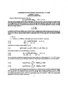
where: Δxi – step size (distance between considered cross sections), h – water level elevation above assumed datum, Q – flow rate, A – wetted cross-sectional area, g – acceleration due to gravity, α – energy correctional coefficient, S – average slope of energy line. The subscripts i and i+1 indicate the considered crosssections. Interpretation of Eq. (1) is given in Fig. 1. Usually the average slope S is considered as the arithmetic mean value taken from both ends of considered interval Δxi
S=
1 (S i + S i +1 ) , 2
(2)
whereas the local slope of energy line is expressed using the Manning formula:
S=
Q2 ⋅ n2 , R 4 / 3 ⋅ A2
(3)
where: R – hydraulic radius, n – Manning roughness coefficient.
Fig. 1. Sketch of a channel reach described by Eq. (1).
Computational issues of solving the 1D steady gradually varied flow equation
The standard step method works very well while solving the typical problems met in river hydraulics – for example the backwater curve behind a dam. Knowing the water stage in cross-section i+1 the unknown water level hi is obtained via solution of Eq. (1). To this order an iterative method must be applied since it is a non-linear algebraic equation with regard to hi . Assume that the steady flow is affected locally because of changing longitudinal bed slope or channel width. When the flow profile varies gently and gradually the standard step method should be applicable as well. Obviously in such a case the refinement of the grid points over the zone of affected flow is required. Unfortunately, such an approach usually fails. As an example, let us consider typical situation in which the obtained results are completely unsatisfactory. EXAMPLE 1 Consider a rectangular channel of length L = 2000 m in which width varies linearly from B = 12 m to b = 6 m at the distance of 100 m. The length of the narrow part is equal to l = 750 m (Fig. 2a). The following data are assumed in this example: roughness coefficient n = 0.025 s/m1/3; initial depth imposed at the downstream end HL = 0.8 m; flow discharge Q = 3.5 m3/s; integration step used in the wide part of the channel is Δxw = 25 m; integration step used in the narrow part of the channel Δxn = 1 m; longitudinal bed slope s = 0.0001; energy correctional coefficient α = 1.1. The flow profile obtained for this example is displayed in Fig. 2b. In the cross-section located at x = 1335 m the computations fail. To provide a better view of the part at which computations fail the close-up of the channel reach between 1335 and 1350 m is shown in Fig. 2c. It can be observed that when the channel width begins to change then the shape of the computed water stage becomes unrealistic. The expanded part of graph h(x) shows that the obtained flow profile has an unrealistic character. The oscillating results give the impression that they represent two different solutions which are accidentally mixed during process of numerical solution. This suggests that solved non-linear equation (1) has more than one root. The computational problems can occur even with the backwater curve computation which in general is performed seamlessly. Usually, such cases of flow are solved with step sizes of order of hundreds of meters. However, it should be possible to obtain a proper solution with an arbitrarily assumed very small step size (Δx = 2 m), for instance, after significant grid refinement. It turns out that in such a case computations also failed. In this situation the following question seems to be relevant: why does Eq. (1) behave in such an untypical way? It appears that explanation of this problem is possible. It can be done on condition that more general analysis of the SGVF is performed. In the next sections it is shown that the standard step method can be considered as the discrete form of the ordinary differential energy equation describing the SGVF. Consequently the untypical properties of the discrete equation can be related to the properties of the ordinary differential equation. Indeed, it appears that the ordinary differential equation for SGVF can have two solutions. Depending on the flow conditions both solutions are physically justified or one of them may be invalid from the physical viewpoint. As the SGVF is a classical problem of open channel hydraulics, it has been a subject of many publications. Several
Fig. 2. Channel with variable width (a), computed water profile (b) and an enlarged part (c). aspects of the SGVF were considered for instance by Chow (1959), Castro-Orgaz et al. (2008), Field et al. (1998), French (1985). In some publications the possibility of multiple solutions of the SGVF equation was reported. Such a problem has been noticed by Dubin (1999), Jan and Chen (2012), Macdonald (1996), Szymkiewicz (2010) and Vatankhah (2011). However, to the best of the authors’ knowledge, the reason for the existence of multiple solutions has not yet been explained on a formal basis. Similarly, although numerical solution of SGVF equations is a commonly applied approach (Abbot, 1979; Cunge et al., 1979; Field et al. 1998; Fread and Harbaugh, 1971; Misra, 1996; Venkatarman et al., 1982), no influence of multiple roots to the process of numerical solution was reported. In this paper an attempt to explain these issues is undertaken. GOVERNING EQUATION FOR SGVF The energy equation is a basic mathematical model for one dimensional SGVF modelling. Usually, it is used in its discrete form given by Eq. (1) (Chanson, 2004; Chow, 1959; Cunge et. al. 1979). However, as flow computations deal with continuous matter, the differential form can be also considered. There are different ways to derive the energy equation in such a form (Szymkiewicz, 2010). The differential energy equation is given by following formula:
dE = −S , dx
(4)
where
E =h+
α ⋅ Q2 . 2
2g ⋅ A
(5) 227
Wojciech Artichowicz, Romuald Szymkiewicz
If lateral inflow is neglected, then mass conservation principle is expressed with
dQ =0 dx
(6)
meaning that Q = const. For a given discharge, Q, the initial value problem for Eq. (4) is formulated: determine the function h(x) which satisfies this equation over the considered solution domain as well as the imposed initial condition: E(x0) = E0. One can use any one of numerous well known numerical methods. However, because of non-uniformly spaced cross-sections in open channels, the single step methods are preferred. An appropriate method for solving of Eq. (4) is the implicit trapezoidal rule which has very good properties. It is implicit, it is absolutely stable and additionally it is A – stable (Ascher and Petzold, 1998), which means that it can be applied to solve even stiff equations. Referring this method to Eq. (4) one obtains:
Ei +1 = E i +
Δ xi (− S i − S i +1 ) , 2
(7)
where: Ei – approximation of E(xi). Introduction of Eq. (7) yields the following approximating algebraic equation:
hi +1 +
α i +1 ⋅ Q
2
2 i +1
2g ⋅ A
=
hi +
αi ⋅ Q
2 2 i
2g ⋅ A
−
Δxi (Si + Si+1 ) . 2
The Lipschitz condition (Ascher and Petzold, 1998) states that the solution of initial value problem for ordinary differential equation
y( x 0 ) = y 0
(9)
exists, is continuous and is unique if there exists a real constant K, such that
| f ( x, y1 ) − f ( x, y 2 ) |≤ K | y1 − y2 | .
228
Q2 ⋅ λ , 8 g ⋅ A2 ⋅ R
(11)
where λ is a friction factor. Taking into account the assumptions listed above, Eq. (4) can be rewritten as follows:
d α ⋅ Q2 Q2 ⋅ λ 1 . H + = − ⋅ dx 2 g ⋅ A2 8g ⋅ B H 3
(12)
Referring Eq. (19) to Eq. (16) the Lipschitz inequality (10) will take the following form:
−
ANALYSIS OF SOLUTION UNIQUENESS OF THE INITIAL VALUE PROBLEM FOR SGVF EQUATION
with
S=
(8)
Note that the discrete mechanical energy equation (8) obtained by approximation of the ordinary differential energy equation (4) using the implicit trapezoidal rule, coincides with Eq. (1) representing “the standard step method” (Chow, 1959; French, 1985). Because the discrete form of energy equation is identical to the standard step method then their numerical properties should be identical as well. Consequently, these properties are determined by the properties of the governing ordinary differential equation (Eq. (4)). Therefore it should be possible to explain them by formal analysis of the ordinary differential equation (4). As the results presented in Figs. 2b and 2c suggest that the discrete energy equation may possess more than one root, then one can expect that the governing ordinary differential equation may have more than one solution. This problem can be explained using the Lipschitz inequality.
dy = f ( x, y ) dx
Let us examine if the Lipschitz inequality is fulfilled in the case of the ordinary differential equation (4) describing the SGVF. To make further analysis easier, let us assume that: − the flow occurs in a horizontal, rectangular channel of width B so that the flow area is equal to A = B·H, − the channel is wide and shallow so that the hydraulic radius can be approximated by the flow depth: R ≅ H, − channel roughness is constant (n = const), − datum is assumed at the level of channel bottom so that the water stage h coincides with the flow depth H. To avoid a real power of the hydraulic radius, energy line slope S is expressed using the Darcy-Weisbach formula which is often used as alternative to the previously mentioned Manning equation:
(10)
Q2 ⋅ λ 1 Q2 ⋅ λ 1 ≤ − − 8 g ⋅ B H 13 8 g ⋅ B H 23 K H1 +
(13)
α1 ⋅ U 12 2g
α ⋅U 2 − H 2 + 2 2 2g
For a small distance Δx between the cross sections 1 and 2 it seems justified to assume that the average cross-sectional flow velocities U1 and U2 differ insignificantly. The same is valid for the Coriolis coefficients α1 and α2. Therefore the difference between the velocity heads can be neglected:
α1 ⋅ U12 2g
−
α 2 ⋅ U 22 2g
≈ 0.
(14)
Similarly, it is assumed that friction factor is constant (λ = const). These assumptions allow rewriting the Lipschitz inequality (13) in the form:
−
Q2 ⋅ λ 1 Q2 ⋅ λ 1 ≤ K | H1 − H 2 | . − − 8g ⋅ B H13 8g ⋅ B H 23
(15)
Note that the constant parameters can be removed from the modulus brackets.
Q2 ⋅ λ 1 1 − 3 ≤ K | H1 − H 2 | . 3 8g ⋅ B H 2 H1
(16)
After reducing the remaining part to the common denominator Eq. (16) takes the following form:
Computational issues of solving the 1D steady gradually varied flow equation
Q 2 ⋅ λ H13 − H 23 ≤ K | H1 − H 2 | . 8 g ⋅ B H 23 ⋅ H13
(17)
The nominator in the absolute value on the left hand side of inequality can be expressed according to the well-known short multiplication formula as:
Q 2 ⋅ λ ( H1 − H 2 )( H12 + H1 ⋅ H 2 + H 22 ) ≤ 8g ⋅ B H 23 ⋅ H13
.
(18)
K | H1 − H 2 | As the water depths H1 and H2 are always positive, therefore relation (18) can be rewritten as
Q 2 ⋅ λ ( H12 + H1 ⋅ H 2 + H 22 ) ⋅ | H1 − H 2 |≤ . 8g ⋅ B H 23 ⋅ H13
considered channel reach of length L. With the water level given at the cross section i+1 by the initial condition or by the preceding step of calculation, the only unknown in Eq. (21) is the water level hi in the previous cross section. Because Eq. (21) is nonlinear with regard to hi it must be solved using an iterative method, such as the bisection method, false position method, Newton method or similar. These methods require that before its application, a separation of all roots of the considered equation must be performed. The solution of Eq. (1) (coinciding with Eq. (21)) presented in Fig. 2b suggests that it may have more than one root. To explain this question let us consider the nonlinear equation (21). To this end, assume that the considered channel reach of length Δx having constant bed slope s is limited by two cross sections denoted by the subscripts 1 and 2 (see Fig. 3). For the right cross section (with subscript 2) all parameters are known, so the only unknown in Eq. (21) is h1.
(19)
K | H1 − H 2 | After dividing both sides of expression (19) by the term | H1 − H 2 | and an appropriate rearrangement one obtains:
Q2 ⋅ λ 1 1 1 + + 8 g ⋅ B H 1 ⋅ H 23 H 12 ⋅ H 22 H 13 ⋅ H 2
≤ K .
(20)
Considering possible values of the parameters in inequality (20), one can notice that there exists no K for which it always holds. Because variables H1 and H2 are present on the left hand side of this inequality, it is neither constant nor bounded. This implies that in the case of ordinary differential equation (4) the Lipschitz inequality is not fulfilled. It means that this equation does not have an unique solution in the considered domain. Consequently the alternative solutions of this equation are possible. ROOTS OF NONLINEAR ALGEBRAIC EQUATION APPROXIMATING THE SGVF DIFFERENTIAL EQUATION If the alternative solutions of energy differential equation (4) are possible, then it is interesting to explain how this fact influences the process of numerical solution of this equation. As after approximation of differential equation with discrete formula, in each step the water stage is obtained via solution of the non-linear algebraic equation, therefore it seems reasonable to expect that alternative solutions can be provided on condition that the algebraic equation has more than one root. This property of Eq. (4) was reported by Szymkiewicz (2010). For detailed examination of this question let us reconsider the numerical solution of initial value problem for ordinary differential equation (4), using the implicit trapezoidal rule: 2
α ⋅Q hi +1 + i +1 + 2 g ⋅ Ai2+1 − hi −
αi ⋅ Q2
2 g ⋅ Ai2
(21)
−
Δxi 2
(− Si − Si +1 ) = 0
This formula allows us to determine the approximated values of function h(x) (0 ≤ x ≤ L) at the selected nodes over the
Fig. 3. Sketch of considered channel reach. Based on Eq. (21), with the datum assumed as in Fig. 3 and introducing the flow depth H instead of the water level h, one can define the following function: α ⋅ Q 2 α ⋅ Q 2 F ( H1) = H 2 − Δx ⋅ s + − H1 + + 2 g ⋅ A22 2 g ⋅ A12 n 2 ⋅ Q 2 Δx n12 ⋅ Q 2 . + + 2 2 R14 / 3 ⋅ A12 R24 / 3 ⋅ A22
(22)
Zeros of function given by Eq. (22) coincide with the roots of Eq. (21). Let us examine the shape of function F(H1) for the following arbitrarily taken set of data describing the flow in rectangular channel: the flow rate Q = 2 m3/s, the channel bed slope s = 0.001, the channel width B = 5 m, the Manning roughness coefficient n = 0.03 s/m1/3, the depth at downstream end of channel interval H2 = 0.75 m. Using assumed data the function (22) is tabulated for the selected values of space interval Δx. The results are plotted in Fig. 4. As can be seen, the shape of function F(H1) is strongly determined by the value of space interval Δx. First of all, in the considered interval (0 < H1 ≤ 1 m) the number of roots of equation F(H1) = 0 varies dependently on Δx value. For small step size values (Δx = 0.5 m and Δx = 1 m) the function has three solutions, otherwise (Δx = 5 m and Δx = 25 m) it has only one solution. The variable number of roots can be explained by analysis of the character of non-linearity appearing in algebraic equation. In Eq. (22) the non-linearity occurs in two terms. The first one describes kinetic energy in cross section 1, while the second one is connected with the energy line slope in the same cross section. The latter one is strongly non-linear and additionally it is multiplied by Δx. The presence of this term is
229
Wojciech Artichowicz, Romuald Szymkiewicz
typical for all implicit methods of integration. Relative contribution of both nonlinear terms in F(H1) varies accordingly to variation of the step Δx. The number of zeros of the function F(H1) depends on the mutual relations between its components (Artichowicz, 2012).
located at its both sides. The shape of function F(H1) suggests that if the root is taken consequently from left side of the critical depth (where H(x) < Hc) then the flow profile corresponding to the supercritical flow will be obtained (Fig. 4). Conversely, if the root is taken consequently from the right side of the critical depth (where H(x) > Hc) then the flow profile corresponding to the subcritical flow will be obtained. Confirmation of the conclusions formulated above is provided by the following numerical test. EXAMPLE 2
Fig. 4. Plots of the function F(H1, Δx) given by the implicit trapezoidal rule. It appears that the multiple roots may occur regardless of the type of numerical method applied for solving SGVF equation (Artichowicz and Szymkiewicz, 2013). Explicit scheme approximation results in algebraic non-linear equations that have two roots regardless of the value of applied space interval Δx, both physically acceptable. It means that in this case two alternative solutions of Eq. (4), coinciding with the energy diagram exist. Two solutions exist even if in the governing SGVF equation the friction is neglected. This property suggests that when performing SGVF computations, in each step two roots are to be expected always when energy equation is approximated with explicit methods. The roots are always placed on both sides of critical depth. One of them corresponds to the subcritical flow, whereas the second one is related to supercritical flow. For this reason, depending on the value of Δx, one can obtain 1, 2 or even 3 roots. However, one can assume as a rule that the nonlinear equation (22) has one or two physical roots always. The (leftmost) third root provides unrealistic water stage profile (Artichowicz and Szymkiewicz, 2013). SELECTION OF THE ROOT CORRESPONDING TO PROPER WATER STAGE PROFILE If the algebraic form of Eq. (4) can have more than one root then the following question becomes relevant: which root should be chosen during the computations? This question is not important as long as the SVGF equation is solved using the implicit method with large value of the space interval Δx since as results from Fig. 4, Eq. (22) has one root only and consequently only one solution is provided. However, if two physically acceptable roots occur, only one should be chosen. If the choice is accidental, then the provided solution can take the form as presented in Figs. 2b, c. Since the function F(H1) is not monotonic, such a situation can take place when the Newton method is applied. There is no doubt that the choice of the appropriate root should be related to the critical depth. Comparing this value with the value of roots one can notice that they are always
230
The SGVF is considered in a rectangular channel with a mild bed slope s = 0.0025, bed width B = 5.0 m and the Manning roughness coefficient n = 0.030 s/m1/3. The channel carries a discharge Q = 2 m3/s for which the critical depth is equal to Hc = 0.262 m, whereas the normal depth is equal to Hn = 0.45 m. Determine the possible water flow profiles h(x) assuming the following initial condition: H(x = 10.0 m) = Hc. A plot of the function F(H1) given by Eq. (22) obtained for the node next to initial one with step size Δx = 0.10 m, is displayed in Fig. 5. One can see that there are two roots located at both sides of the minimum point of F(H1), which is very close to H1 = Hc. The choice of the root depends on the type of required curve. If the curve corresponding to tranquil flow is searched, then the root at the right side of the extreme point must be systematically chosen. Conversely, if the curve corresponding to rapid flow is computed, then the root from the opposite side should be systematically taken.
Fig. 5. Function F(H1) plot for initial condition H(x = 10 m) = Hc = 0.262 m and Δx = 0.10 m. The results of computations are displayed in Fig. 6.
Fig. 6. Two alternative flow profiles computed for the same initial condition H(x = 10 m) = Hc.
Computational issues of solving the 1D steady gradually varied flow equation
Let us reconsider Example 2 in which flow along narrowing channel was analysed (Fig. 2a, b, c). However this time, during computations the root corresponding to tranquil flow was consequently chosen as in this example flow profile corresponding to the subcritical flow was expected. Application of proper root choice strategy leads to physical outcome of this numerical experiment. Indeed, as one can see in Fig. 7, by choosing proper root of Eq. (22) it is possible to compute a physically justified solution.
lying at left hand side of the critical stage is selected. In such a way, the computations provide the flow profile h(x) which gradually passes from the subcritical flow regime to supercritical. The idea presented above was verified by performing an experiment. In order to obtain the reliable data, the SGVF in laboratory flume of width B = 0.40 m and of length equal to 10 m with adjustable longitudinal slope was used. EXAMPLE 3
Fig. 7. Flow profile computed for narrowing channel with step size Δx = 1 m.
The uniform longitudinal bed slope of laboratory flume was locally modified to arrange the required conditions for passing from the subcritical to supercritical flow. To this end, an element which changed the bed slope at certain distance was installed inside the flume (Fig. 9). This element narrowed the flume so that the width of installed section is B = 0.38 m. The Manning roughness coefficient was evaluated as equal to n = 0.010 s/m1/3. It was assumed that over the first section of channel with bed slope equal to s1 = 0.0017 subcritical flow takes place (Fig. 9). Towards the downstream end the bed slope increases. It takes the values of s2 = 0.0752 and s3 = 0.0454 respectively (Fig. 9). During the experiment the following flow parameters were measured: flow discharge Q = 16.90 Litres/s, water stage at the upstream end h0 = 16.4 cm, flow depth at the upstream end H0 = 6.5 cm. For these flow parameters the critical depth in the flume bed was Hc = 5.86 cm.
DETERMINATION OF OPEN CHANNEL FLOW PROFILE WITH PASSING THROUGH CRITICAL STAGE AND ITS EXPERIMENTAL VERIFICATION As was shown in the previous section, the ordinary differential energy equation (4) has two alternative solutions that can be obtained via the choice of proper root depending on the considered flow regime. In open channel hydraulics we very often face the situation where the flow regime changes (Fig. 8).
Fig. 9. Sketch of channel section with variable slope installed in the laboratory flume.
Fig. 8. Passing from the subcritical to the supercritical flow. Let us assume that the computation starts with initial condition greater than the critical stage h(x = 0) = h0, where the subcritical flow takes place. With accepted step size Δx the approximated values of flow profile h(x) are calculated in subsequent nodes. As is known, in fact the point at which the flow profile passes through critical stage occurs before bed slope change. To overcome this particular point, in proposed approach it is assumed that the root of Eq. (22) from right hand side of the critical stage is chosen for all nodes placed before bed bend point xb (Fig. 8). After passing the point of channel’s intersection, instead of the root from right hand side this one
The measured flow profile corresponding to existing flow conditions and flume geometry is displayed in Fig. 10 using dots. The ordinary differential energy equation was solved using the implicit trapezoidal rule with Δx = 0.0125 m. The initial condition was imposed in the cross-section located at x=0.6 m (Fig. 9). At first, no root choice strategy was applied even when the process of computation passed bend point xb, so the root was selected randomly. Consequently, the solution was similar to the one obtained in Example 2 and presented in Fig. 2c. Such water stage profile is completely unacceptable. In the next test, during computations over the first section of flume the root corresponding to the depth greater than critical one was taken. For the next sections, having the bed slopes greater than supercritical one, computations were performed in two ways. At the first one, the root lying at left side of the critical depth and corresponding to the supercritical flow was chosen. Consequently the flow profile corresponding to the supercritical flow has been obtained. In Fig. 10 it is marked using solid line.
231
Wojciech Artichowicz, Romuald Szymkiewicz
As one can see, the agreement of computed and observed flow profiles is quite satisfactory. The greatest difference between the computed and observed water levels, equal to 0.007 m, occurred in cross-section at which the mild bed slope of the first section increases. The other time root lying on the right hand side of critical depth was chosen resulting in a non-real solution (Fig. 10). Taking into account the obtained results one can find out that while solving the SGVF equation the essential meaning has appropriate selection of the root of non-linear algebraic equation approximating the ordinary differential energy equation. By choosing the proper root of the approximating equation one can compute the flow profile h(x) which passes through the critical stage.
Fig. 10. Flow profiles observed and computed in the flume with variable bed slope for Q = 16.90 Litres/s. CONCLUSIONS Analysis of the numerical aspects of solution of the ordinary differential equation for the steady gradually varied flow in open channels allows the formulation of several conclusions. First of all, the ordinary differential energy equation is a more general description of the SGVF. From this equation the standard SGVF equation involving the Froude number can be derived. Moreover numerical solution of the energy equation using the implicit trapezoidal rule provides the algebraic formula which coincides with the standard step method. Using the Lipschitz inequality it was shown that the initial value problem for the ordinary differential energy equation has no unique solution. Consequently the discrete energy equation can have 1, 2 or even 3 roots, depending on the circumstances. Two roots can be physically justified. Consequently, it is possible to obtain two alternative numerical solutions. This is valid for the standard step method as well. The problem of nonuniqueness of the solution can be unnoticeable in the some cases. When the SGVF equation is numerically solved using the implicit method and additionally the computations are carried out with a relatively large step size Δx being of order of hundreds or thousands meters, the algebraic equation approximating the ordinary differential one has one root only. In general case the number of roots is determined by the type of applied numerical method (explicit or implicit) and the value of applied step size. As both possible solutions have physical sense, during numerical solution the root of the nonlinear algebraic equation must be selected carefully taking into account the kind of flow
232
regime reproduced in open channel. Due to this property, the ordinary differential energy equation can be used for both subcritical and supercritical flow. Consequently it is possible to perform computations of the water flow profile h(x) over a channel reach where the flow regime changes passing through the critical stage. REFERENCES Abbot, M.B., 1979. Computational Hydraulics: Elements of the Theory of Free-Surface Flows. Pitman, London. Artichowicz, W., 2012. Numerical modeling of steady gradually varied flow in open channels. PhD Thesis. Gdansk University of Technology, Faculty of Civil and Environmental Engineering, Gdansk. Artichowicz, W., Szymkiewicz, R., 2013. Properties of one dimensional open-channel steady flow equations. In: Proc. 13th International Symposium on Water Management and Hydraulic Engineering, Bratislava, Slovakia. Ascher, U.M., Petzold, L.R., 1998. Computer Methods for Ordinary Differential Equations and Difference-Algebraic Equations. SIAM, Philadelphia. Castro-Orgaz, O., Giráldez, J.V., Ayuso, J.L., 2008. Energy and momentum under critical flow conditions. Journal of Hydraulic Research, 46, 6, 844–848. Chanson, H., 2004. The Hydraulics of Open Channel Flow: An Introduction. Second Edition. Elsevier, Oxford. Chippada, S., Ramaswamy, B., Wheeler, M.F., 1994. Numerical simulation of the hydraulic jump. International Journal for Numerical Methods in Engineering, 37, 8, 1381–1397. Chow, V.T., 1959. Open-channel Hydraulics. McGraw-Hill / Kogakusha Company LTD, Tokyo. Cunge, J.A., Holly, F.M., Verwey, A., 1979. Practical Aspects of Computational River Hydraulics. Pitman, London. Dubin, J.R., 1999. On gradually varied flow profiles in rectangular open-channels. Journal of Hydraulic Research, 37, 1, 99–106. Field, W.G., Lambert, M.F., Williams, B.J., 1998. Energy and momentum in one dimensional open channel flow. Journal of Hydraulic Research, 36, 1, 29–42. Fread, D.L., Harbaugh, T.E., 1971. Open-channel profiles by Newton’s iteration technique. Journal of Hydrology, 13, 70– 80. French, R.H., 1985. Open Channel Hydraulics. McGraw-Hill, New York. Goutal, N., Maurel, F., 2012. A finite volume solver for 1D shallow-water equations applied to an actual river. International Journal for Numerical Methods in Fluids, 38, 1–19. Jan, C.-D., Chen, C.-L., 2012. Use of the Gaussian hypergeometric function to solve the equation of graduallyvaried flow. Journal of Hydrology, 456–457, 139–145. Le Veque, R.J., 2002. Finite Volume Methods for Hyperbolic Problems. Cambridge University Press, Cambridge. Macdonald, I., 1996. Analysis and computation of steady open channel flow. PhD Thesis. University of Reading, Reading. Misra, R., 1996. Spatially varied steady flow in irrigation canals. Agricultural Water Management, 30, 2, 217–235. Szydłowski, M., 2004. Implicit versus explicit finite volume schemes for extreme, free surface water flow modelling. Archives of Hydro-Engineering and Environmental Mechanics, 51, 3, 287–303. Szymkiewicz, R., 2010. Numerical Modeling in Open Channel Hydraulics. Springer, Dordrecht, Heidelberg, London, New York.
Computational issues of solving the 1D steady gradually varied flow equation
Toro, E.F., 1999. Riemann Solvers and Numerical Methods for Fluid Dynamics. A Practical Introduction. Springer, Dordrecht, Heidelberg, London, New York. Vatankhah, A.R., 2011. Direct integration of gradually varied flow equation in parabolic channels. Flow Measurement and Instrumentation, 3, 22, 235–241.
Venkatarman, P., Nasser, M.S., Ramamurthy, A.S., 1982. Dynamic equations for steady spatially varied open channel flow: a critical review. Advances in Water Resources, 5, 2, 66–72. Received 28 February 2014 Accepted 17 July 2014
233