Computational Steering in the Problem Solving Environment WBCSim Jiang Shu1 , Layne T. Watson1,2, † ,‡ , Naren Ramakrishnan1, Frederick A. Kamke3 , and Shubhangi Deshpande1 1
Department of Computer Science, Virginia Polytechnic Institute and State University, Blacksburg, Virginia 24061, U.S.A. 2 Department of Mathematics, Virginia Polytechnic Institute and State University, Blacksburg, Virginia 24061, U.S.A. 3 Department of Wood Science and Engineering, Oregon State University, Corvallis, Oregon 97331, U.S.A.
SUMMARY
Computational steering allows scientists to interactively control a numerical experiment and adjust parameters of the computation on-the-fly and explore “what if” analysis. Computational steering effectively reduces computational time, makes research more efficient, and opens up new product design opportunities. There are several problem solving environments (PSEs) featuring computational steering. However, there is hardly any work explaining how to enable computational steering for PSEs embedded with legacy simulation codes. This paper describes a practical approach to implement computational steering for such PSEs by using WBCSim as an example. WBCSim is a Web based simulation system designed to increase the productivity of wood scientists conducting research on wood-based composites manufacturing processes. WBCSim serves as a prototypical example for the design, construction, and evaluation of small-scale PSEs. Various changes have been made to support computational steering across the three layers—client, server, developer—comprising the WBCSim system. A detailed description of the WBCSim system architecture is presented, along with a typical scenario of computational steering usage. KEYWORDS: computational steering, problem solving environment, computing environment, wood-based composite materials, database management
†Correspondence to: Layne T. Watson, Department of Computer Science, Virginia Polytechnic Institute and State University, Blacksburg, VA 24061, U.S.A. ‡ E-mail:
[email protected]
Contract/grant sponsors: Virginia Polytechnic Institute and State University, Wood-based Composites Center, U.S. Department of Agriculture, National Science Foundation, Department of Energy; contract/grant numbers: 1997 ASPIRES, 97-35504-4697, DMI-0422719, DMI-0355391, and DE-AC04-95AL97273-91830.
1
1.
INTRODUCTION
Every day, computational scientists from various disciplines, such as wood science, physics, chemistry, and biology, using various computing environments, perform numerical experiments on their computers. Each of these numerical experiments (hereafter referred to as an experiment) goes though similar life cycles even though these sciences have very little in common. Ioannidis et al. [19] identified three stages in a typical experiment life cycle: 1) design of experiment, 2) data collection, and 3) data exploration. Besides the possible evolving nature of the design of experiment stage, scientists often focus their research on data collection and data exploration. Moreover, beyond just monitoring a running simulation and viewing the final results at the end, the scientists may wish to interactively control an experiment. This is known as “computational steering”, which allows scientists to adjust parameters of the computation on-the-fly and explore “what if” analysis [14]. This often helps scientists deepen their understanding of underlying principles. As effects due to changes in parameters become more instantaneous, the cause-effect relationships could become more evident [29]. Mulder et al. [28] further classified the three main uses of computational steering as: model exploration, algorithm experimentation, and performance optimization. With model exploration, computational steering is used to explore parameter spaces and simulation behavior to gain additional insight into the simulation model. In algorithm experimentation, computational steering allows the user to adapt program algorithms during the run, for instance to experiment with different numerical methods. In performance optimization, steering is used to manually improve an application’s performance, e.g., to perform load balancing interactively in parallel applications. A problem solving environment (PSE) is a computational system that provides a complete and convenient set of high-level tools for solving problems from a specific domain [32]. A PSE commonly addresses many issues: Internet accessibility to legacy codes, visualization, experiment management (EM), multidisciplinary support, recommender systems, collaboration support, optimization, high performance computing, preservation of expert knowledge, design extensibility, and pedagogical uses [44]. SCIRUN [29] is a framework for PSE construction from domain specific packages (such as the BioPSE package), which consist of predefined data types, algorithms, and modules. Such a framework enables the user to design scientific simulations and interactively control such simulations. Discover [25] is a PSE focusing on a rule-based visualization system and optimization. Section 2 provides more details about SCIRUN, Discover, and other computing environments with computational steering capability. These PSEs with computational steering capability generally focus on the construction of new simulations rather than making computational steering work for an existing PSE embedded with legacy simulation code, especially large scale simulation codes written decades ago without computational steering design in mind. This paper describes a practical implementation of a minimal set of components to enable computational steering capability by using WBCSim as an example. WBCSim is a PSE that increases the productivity of wood scientists conducting research on wood-based composite (WBC) materials and manufacturing processes. It integrates Fortran 90 simulation codes with a Web based graphical front end, an optimization tool, and various 2
visualization tools. The WBCSim project was begun in 1997 with support from USDA, Department of Energy, and Virginia Polytechnic Institute & State University (VPI). It has since been used by students in several wood science classes, by graduate students and faculty, and by researchers at several forest products companies. WBCSim also serves as a test bed for the design, construction, and evaluation of useful, production quality PSEs. Goel et al. [16], [17] described an early version of WBCSim. Over the years, WBCSim has evolved in many ways. More advanced simulation models such as a mat formation model and a hot compression model are now incorporated into the system [35]. An experiment management tool [34] is also included now. This EM tool uses a database management system (DBMS) to store simulation input and results at the server end, provides helpful graphical interfaces to facilitate user access at the client side, and then uses various scripts to connect all of these components. Recently, XML (Extensible Markup Language) was used to unify the implementation layers of WBCSim [33]. A XML datasheet is tailored for each model (WBCSim has five models). The WBCSim interface layer, server scripts, and database management system all use this XML datasheet to improve the usability and maintainability of the three layers—client, server, developer—comprising the WBCSim system. This paper shows that with a reasonable number of changes, with a small set of components, a computational steering capability can be achieved for any PSE embedded with legacy simulation codes. This small set of changes and components includes 1) designing and adding a very simple steering module at the legacy simulation code level, 2) providing a way to monitor simulation execution (alert users when it is time to steer), 3) adding an interface to access and visualize simulation results, and even compare intermediate results across multiple steering attempts. This paper describes in detail how such changes and components are implemented in WBCSim, and how computational steering can effectively reduce computational time, make research more efficient, and open up new product design opportunities. The paper is organized as follows. Section 2 reviews some related work in PSEs and computational steering. Section 3 briefly describes WBCSim. Section 4 gives the motivation for adding computational steering capability. Section 5 elaborates on the WBCSim user interface, the model interface similarities, and also the unique aspects of the hot compression model, which is used to demonstrate the computational steering feature. Section 6 explains the architecture of WBCSim and how the computational steering capability is developed within this architecture. Section 7 demonstrates a typical scenario of computational steering for WBCSim. Section 8 generalizes the WBCSim computational steering work and summarizes the lessons learned. Section 9 outlines some future directions of computational steering for WBCSim and draws conclusions. 2.
RELATED WORK
There are many problem-specific PSEs developed for various application domains. Some of these PSEs have computational steering capabilities. 2.1.
Problem Solving Environments
A PSE is a relatively new computing paradigm that was first introduced in problem domains such as partial differential equations (ELLPACK [16] and its descendents [8] for solving two3
and three-dimensional elliptic partial differential equations) and linear algebra (Linear System Analyzer [4] for manipulating and solving large-scale sparse linear systems of equations). Since then, many new PSEs have been introduced. Gismo [9], created at Washington University, is an object oriented Monte Carlo package for modeling all aspects of a satellite’s design and performance. It has played a significant role in the design of the Gamma Ray Large Area Space Telescope, the successor to the Compton Gamma Ray Observatory that was launched into space in 1991 to explore the gamma ray portion of the electromagnetic spectrum for astrophysics research. VizCraft [15], developed at Virginia Polytechnic Institute and State University, provides a graphical user interface for a widely used suite of analysis and optimization codes that aid aircraft designers during the conceptual design of a high speed civil transport. VizCraft combines visualization and computation, encouraging the designer to think in terms of the overall problem solving task, not simply using the visualization to view the computational results. Also, a computing environment developed by Chen et al. [10], which combines particle systems, rigid body particle dynamics, computational fluid dynamics, rendering, and visualization techniques to simulate physically realistic, complex dust behavior, has been shown to be useful in interactive graphics applications for education, entertainment, or training. Expresso [36], a microarray experiment management PSE, is designed to assist biologists in planning, executing, and interpreting microarray experiments. It serves as a unifying framework to study data-driven application composition systems, as envisaged under the NSF Next Generation Software (NGS) program. Physical and analytical stages of the microarray process are mirrored in Expresso with computational models from biophysics, molecular biology, biochemistry, robotics, image processing, statistics, and knowledge representation. These models are pushed deeper (earlier) into the design process to help avoid costly design errors and to provide, as needed, surrogate functions for the traditional stages of microarray experiments. L2W [11] is a PSE for land use change analysis. L2W organizes and unifies the diverse collection of software typically associated with ecosystem models (hydrological, economic and biological). It provides a Web based interface for potential watershed managers and other users to explore meaningful alternative land development and management scenarios and view their hydrological, ecological, and economic impacts. The JigCell model builder [2], [39], [1], [40], allows users to define chemical kinetic models as a set of reaction equations using a spreadsheet (an example of direct entry of equations) and outputs model definitions in the Systems Biology Markup Language. This spreadsheet paradigm demonstrates its effectiveness in reducing the number of errors made by systems biology modelers when compared to hand conversion of a metabolic pathway wiring diagram to differential equations. Site Specific System Simulator for Wireless System Design (S 4 W ) ([37], [27]) is a PSE that integrates visualization and computational tools with a high level graphical user interface. S 4 W improves the ability of wireless system engineers to design an indoor wireless system by encouraging them to think in terms of designing the system for optimal performance, while issues of computation management, data management, and location of computer resources are hidden from the user. The Land Information System (LIS) [21] is a multiscale hydrologic modeling and data assimilation framework that integrates the use of satellite and ground based observational data products with advanced land-surface modeling tools to aid several application areas, including water resources management, numerical weather prediction, agricultural management, air quality, and military mobility assessment. 4
Watson et al. [44] present a thorough summary of the key attributes of a PSE (described in Section 1), and also compare a PSE with other similar computing environments—a decision support system (DSS) and a geographic information system (GIS). Roughly, a DSS emphasizes the functionality (analysis, planning, and decision making), a GIS emphasizes the nature of data and information (spatial), while a PSE emphasizes the problem domain (such as woodbased composite materials). 2.2.
Computational Steering
In 1987, a US National Science Foundation workshop on scientific visualization reported that scientists want to drive the scientific discovery process and interact with their data. Interactive visual computing is a process allowing scientists to communicate with the data production process and manipulate data visualization during that process. Such a sophisticated process could allow scientists to steer, or dynamically modify computations while they are occurring [26]. The computational steering concept became established, and developed and flourished in the 90s and the turn of the century, when it has been applied in many scientific domains such as pollution analysis [5], molecular dynamics simulations [25], and medicine (cardiology and neuroscience) [29]. SCIRun [29] is one of the oldest PSEs that allows the interactive construction, debugging, and steering of large-scale scientific computations designed with predefined domain specific packages. The primary purpose of SCIRun is to enable the user to interactively control scientific simulations while the computation is in progress. This control allows the user, for example, to vary boundary conditions, model geometries, and/or various computational parameters during simulation. DISCOVER [25] is an interactive and collaborative PSE that enables geographically distributed scientists and engineers to collaboratively monitor and control parallel/distributed applications using Web based portals. The DISCOVER interaction servers build on servlet technology and enable clients to connect to, and collaboratively interact with, registered applications using a conventional browser. Geographically distributed servers are interconnected using CORBA. DISCOVER also has a concept of rule based visualization. These rules are decoupled from the system and can be externally injected to manage visualization behaviors at runtime, such as automatically selecting the appropriate visualization routines and methods, and adjusting the extraction threshold. CUMULVS [14] is a software infrastructure for developing collaborative environments. It supports interactive visualization and remote computational steering of distributed applications by multiple collaborators. In particular, CUMULVS provides a mechanism for constructing fault tolerant check points, and migrating applications in heterogeneous distributed computing environments. Computational Steering Environment (CSE) [24] provides an environment that allows scientists to easily define an interactive interface to an ongoing simulation. The architecture of CSE is a set of processes, called satellites, which implement standard visualization operations. The simulation itself is also packaged as a satellite. Satellites cooperate with each other by communicating data to a central data manager, which, in turn, notifies any interested satellites about data change. Falcon [12] is a set of tools that collectively support on-line program monitoring and steering of parallel and distributed applications. The four major conceptual components of Falcon include (1) a monitoring specification mechanism, which consists of a low level sensor 5
specification language and a high level view specification language, (2) mechanisms for on-line information capture and analysis, (3) mechanisms for program steering, and (4) an associated system for the construction and use of graphical displays of program information. In a survey of computational environments, Mulder et al. [28] discussed computational steering from various aspects such as scope, architecture, and user interface. They further compared VASE [18], [20], SCIRun [29], Progress/Magellan [42], [43], CUMULVS [14], VIPER [30], and CSE [24]. In a grid (distributed computational grid) context, there are several other computational steering systems such as GVIZ [5], RealityGrid [7], and AutoPilot/Virtue [41]. These systems vary by their steering method, visualization interface, and scheme of incorporation within a grid environment.
3.
WBCSIM
WBCSim is intended to increase the productivity of wood scientists conducting research on wood-based composite materials by making legacy file based Fortran programs that solve scientific problems in the wood-based composites domain widely accessible and easy to use. WBCSim currently provides Internet access to command line driven simulations developed by the Wood-Based Composites Center at VPI. WBCSim leverages the accessibility of the World Wide Web to make simulations with legacy code available to scientists and engineers away from their laboratories. WBCSim currently supports five simulation models that help wood scientists studying woodbased composite material manufacturing. (1) Rotary dryer simulation (RDS). The rotary dryer simulation model assists in the design and operation of the most common type of system used for the drying of wood particles [22], [23]. (2) Radio-frequency pressing (RFP). The radio-frequency pressing model [31] was developed to simulate the consolidation of wood veneer into a laminated composite using high frequency energy. (3) Oriented strand board mat formation (OSB). The mat formation model [47] creates a three-dimensional spatial structure of a layered wood-based composite (e.g., oriented strand board and waferboard); it also calculates certain mat properties by superimposing a mesh on the mat structure. (4) Hot compression (HC). The hot compression model ([48], [49]) simulates the mat consolidation and adhesive cure that occurs during industrial hot-pressing of wood-based panels. (5) Composite material analysis (CMA). The composite material analysis model [35] was developed to assess the stress and strain behavior and strength properties of laminated materials (e.g., plywood and fiber-reinforced composites). The current software architecture of WBCSim follows the three tier model described by Goel et al. [16], in which the tiers are (1) the client layer—user interface, (2) the server layer—Web server and a PHP module, and (3) the developer layer—legacy simulation codes and various optimization and visualization tools running on the server. Section 6 elaborates on the details of the three layers while explaining how the computational steering fits into this architecture. 6
WBCSim is equipped with an optimization algorithm DOT (Design Optimization Tool) [38] and various visualization tools: VRML [3], Mathematica [45], and the UNIX utility WhirlGif. The reader is referred to [35] for an in-depth treatment of these tools. In 2004, Shu et al. [34] described a WBCSim experiment management component, which integrates a Web based graphical front end, server scripts, and a database management system to allow scientists to easily save, retrieve, and perform customized operations on experimental data. In 2008, Shu et al. [33] described how XML is used to unify the implementation layers for WBCSim. A XML datasheet is tailored for each of the five models (mentioned above). The WBCSim interface layer, server scripts, and database management system all use this XML datasheet to improve the usability and maintainability of the client, server, and developer layers. XML is the acronym for Extensible Markup Language, which allows a developer to create customized tags, supporting the definition, transmission, validation, and interpretation of data within/between applications, and among organizations. As WBCSim has evolved in various ways throughout many years, its original goals remain the same: (1) to increase the productivity of WBC research and manufacturing groups by improving their software environment, and (2) to continue serving as an example for the design, construction, and evaluation of small-scale problem solving environments.
4.
RATIONALE FOR COMPUTATIONAL STEERING
The more advanced models in WBCSim, such as the hot compression model (a twodimensional nonlinear partial differential equation), its Fortran 90 core program and its visualization/optimization tools, can take hours to run on a fast (Sun Blade 2000) workstation. As mentioned above, the simulation result could be undesirable after such a long wait. Some initial results could enable scientists to avoid this wait, and effectively direct the simulation toward other more promising outcomes. Moreover, scientists are very interested in some intermediate processes in the simulation that could alter the final results. For example: the hot press closure time lasts for 15 to 60 seconds, but it could be carefully examined to see how it affects the characteristics of the final panel; the build-up of gas pressure inside the mat during the hot compression process can be studied to see if it is possible to reduce the press time and yet still achieve adequate cure of the adhesive. By augmenting WBCSim with computational steering capability, many of these questions can be investigated and possibly answered. In short, computational steering in WBCSim is a tool for model exploration, which could reduce computational time, make research more efficient, and open various new opportunities in the following ways. (1) Computational steering provides interactive control that could save countless hours of wasted computation time waiting for final failed or uninteresting simulation results whose nature might have been apparent from the first few iterations. (2) By showing the intermediate results, cause and effect relationships could be evident. That could prompt the scientist to conduct various “what if” scenarios, which could lead to interesting discoveries. 7
(3) Scientists can concentrate on certain interesting parts/steps of the simulation and study them in a more controlled/interactive manner, and see how those parts affect the computation as a whole. (4) Humans (scientists) are again being placed in the center of the computation. Thus, human expert knowledge can be effectively leveraged to steer a large computation to a goal. (5) Computational steering also opens doors for automated optimization, if scientists can define the boundary conditions and goals properly.
5.
USER INTERFACE
In 2008, Shu et al. [33] described how the WBCSim Java applet interface (browser plug-in technology) can be replaced by PHP (server scripting technology) code. PHP stands for Hypertext Preprocessor, which is an open source, server-side, HTML embedded scripting language used to create dynamic Web pages. Other similar server scripting technologies are JSP (Sun) and ASP (Microsoft). Upon any HTTP request, the server runs PHP scripts and sends plain HTML code back to the client, where no plug-in is needed. A user launches the WBCSim Web page from a browser window, which contains a list of the simulation models that WBCSim supports. Under each model, a user can either choose to enter a simulation model by clicking “Use This Model as Guest” or read more information about the model by clicking “Detailed Description”. Upon entering a particular simulation model, a user has the choice of creating a new simulation, or investigating the stored simulation runs. There are additional choices at the right top corner of the page to allow a user to go back to the home of the current model, switch models, refresh a page, enable frames, submit comments, and logout; there is also a question mark icon that leads to help. These additional choices are always at the top and the bottom (in case the Web page is too long) of the page to help a user. There are two kinds of stored simulation runs—incomplete ones and complete ones. For incomplete simulation runs, a user can resume and finish off the simulation. For complete simulation runs, a user can view the result of that simulation, change the input values of the simulation to run it again, and perform an “Advanced Option”. In the “Advanced Option”, a user is allowed to filter the simulation runs displayed. By selecting either “Title” or “Date” radio buttons, a user can narrow the filter process to either field. Then a user can input a regular expression (in UNIX grep style) in the text field, and press the “Filter” button to execute the filter process, which will reload this Web page with the simulation runs that meet the filter criteria. The “Advanced Option” also allows a user to apply comparison functions by selecting an item from the “Compare Option” dropdown list. Each model of WBCSim has its own comparison functions. For example, the OSB model has three, which allow a user to compare “Void Fractions/Contact Area”, “Density”, and “Coefficient of Variation” among the simulation runs selected. If “Void Fractions/Contact Area” is selected from the “Compare Option” dropdown list, a new page is loaded with more options that allow comparisons among “space/mat”, “lumen/mat”, “void/mat”, “lumen/flake”, and “contact area”. A user can also specify the interval of the Y-axis in order to narrow the comparison. To the right of these stored simulation runs, there is information about model specific alerts and announcements and a user profile. 8
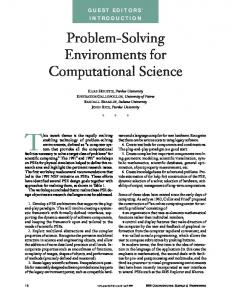
If a user decides to create a new simulation, he will actually see the specific model interface. There are some common features among all the model interfaces (see Fig. 1). Under the “WBCSimulator” title, there is a series of names and arrows to show the current navigation stage. In the left frame, there are many links corresponding the necessary steps to run a particular simulation model. When these links are clicked, the corresponding Web pages will show up in the right frame. The first link is “Introduction” that explains the model behavior at an abstract level, and also gives general directions about how to use the model. The next link is “Set Name”, which allows a user to describe the simulation. Following “Set Name”, there are model-dependent links to allow a user to specify necessary simulation parameters in the right frame with any number of text boxes, dropdown lists, radio buttons, or plain buttons. At the bottom of left frame, there are links to “Run Simulation”, “Save Inputs”, “Save Results” and “Delete”. The “Run Simulation” link will display a Web page to confirm and send the HTTP request to execute the proper PHP code with input values defined in the interface. This will cause a UNIX or PERL script to run compiled Fortran code, and any additional optimization or visualization codes. The “Save Inputs” link will only save the input values in the database as an incomplete simulation run, while the “Save Results” link will save both inputs and outputs in the database as a complete simulation run. The “Delete” link will delete the current simulation run from the database and any associated files. The “View Results” link will appear right under ”Save Inputs” if a simulation is executed. The “View Results” will show the simulation results in both textual (normally tables of numbers) and graphical (VRML files, GIF files) forms. The HC model (Fig. 1) interface differs from the other model interfaces by dividing the simulation parameters into four groups in the left frame menu: (1) model inputs, (2) model parameters (execution specification), (3) steering, and (4) model outputs. The first group contains links for specifying the parameters related to the steering setup, material, initial condition, boundary condition, adhesive cure, and press schedule. The second group defines the HC model execution by specifying mat transport properties, boundary transport properties, and compression properties. The third group provides intermediate results and options to steer the simulation during the run. The last group specifies the output, such as color or black and white, the time interval for generating frames for animation, and other parameters determining which data/image files are generated. This paper focuses on demonstrating the computational steering feature via the HC model, as more steering specific features will be elaborated upon in the next two sections. The reader can refer to [33] for more interface related details about the other models such as the RDS, RFP, OSB, and CMA models.
6.
ARCHITECTURE
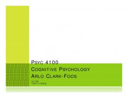
The current software architecture of WBCSim follows the three-tier model described by Goel et al. [16], in which the tiers are (1) the client layer—user interface, (2) the server layer— Apache Web server and a PHP module, and (3) the developer layer—legacy simulation codes and various optimization and visualization tools running on the server. These layers are shown in Fig. 2. 9
6.1.
Client Layer
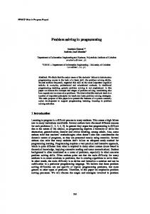
The client layer is the only layer visible to end-users and typically the only layer running on the local machine. The main part of the client layer is the user interface, which is described in the previous section. The user interface is generated from PHP and XML. As described earlier, each model has a XML datasheet, which uses a set of customized tags to describe the model. Readers can find some of these tags described in [33]. At the beginning of the PHP script, it reads the model specific XML datasheet and uses a XML parser to parse the information into an array structure. Then different parts of the PHP script use this array to construct interfaces, set parameter defaults, store user inputs, and assemble the inputs into a string (the corresponding simulation wrapper will feed this string to the Fortran simulations). Therefore, adding a parameter in the XML datasheet will simply add an element in the dynamic array. Then, the PHP code referring to this array will automatically update the interface when executed. To support computational steering for the HC model, a parameter section called “Steering Setup” is added under the input section in the left frame menu (see Fig. 1). A user can specify the number of iterations for steering (how many times to steer), the maximum wait time per steering (when this time expires, the simulation will continue as normal), and the stepwise wait time (the simulation time intervals at which the simulation will check for steering inputs). There is another menu section called “Steering” added before “Output Parameters”. Through the “Steering” menu, a user can view the intermediate results (plots and data files) of a running simulation, and enter new values for the steerable parameters. Such interface changes are done quite easily by changing the corresponding HC XML datasheet. PHP code was altered to allow “Steering” to invoke a new PERL wrapper code running on the server, which generates plots for intermediate results and creates steering inputs to the HC Fortran program. After starting a simulation in WBCSim, there is a log window where a user can monitor the progress of a simulation run (see Fig. 3). The PERL wrappers and the FORTRAN program all pipe their outputs to one log file per one simulation run. The log window simply takes such a log file to display in a browser window. Previously, a user had to click the “Refresh” button to refresh the contents of a log window manually. In order to better notify the user when it is time to steer, the log window is now programmed to refresh itself every five seconds. Moreover, for a long simulation run (such as 30 minutes), a user does not have to stare at the log window waiting for the right time to steer; instead, he can work on any other applications on his desktop. When the steering time arrives, this log window will pop out to the front of all the windows and take the focus. This alerts the user to go to the “Steering” menu to examine the intermediate results and steer. The client layer also contains viewers for the visualization tools: the VRML translator in the HC model case. The reader can refer to [33] for more details. In summary, the client layer handles communication with the server layer by sending HTTP requests. When a user clicks a link, a URL appended with necessary action commands and parameters is sent to a Web sever in the server layer, where the corresponding PHP scripts, along with other possible PERL scripts (including steering), visualization tools, and database operations, are executed. 10
6.2.
Server Layer
By separating the legacy simulation codes from the user interface, the server layer functions as the key to how WBCSim can run a text-only application from a Web browser. The server layer consists of two components: an Apache HTTP server and a PHP module. Reference [33] describes why an old telnet connection method used in the original version of WBCSim [17] is untenable. The old telnet connection method creates a security hole by asking the client to open a special network port in order to communicate with the server. Currently, by requiring the standard Apache HTTP server with a PHP module, the server only needs the standard HTTP port 80, which is the standard and normally open/monitored port at the client computer for Web browsing. The Apache HTTP Sever Project (http://httpd.apache.org/) is a collaborative software development effort aimed at creating a robust, commercial-grade, featureful, and freely-available source code implementation of an HTTP (Web) server. The project is jointly managed by a group of volunteers located around the world, using the Internet and the Web to communicate, plan, and develop the server and its related documentation. The January 2009 Netcraft Web Server Survey (http://news.netcraft.com/archives/web server survey.html) found that more than 52% of the Web sites on the Internet are using Apache, thus making it more widely used than all other web servers combined. The PHP module serves as a plug-in to the Apache HTTP server. When the HTTP server receives a request to process a PHP file, the PHP module will parse and execute that PHP file and return HTML back to the client. This PHP module supports sessions. A session is a series of related interactions between a single client and the Web server, which can take place over an extended period of time. By using sessions, the PHP module can concurrently accept multiple requests from different clients and direct executions of multiple simulations. The server layer is flexible enough to handle computational steering without any change. 6.3.
Developer Layer
As its name suggests, the developer layer consists of legacy programs created by researchers to model WBC materials and manufacturing processes. These legacy programs are the heart of WBCSim. In general, WBCSim supports legacy programs written in any programming language as long as the program takes its input parameters from UNIX stdin. The input parameters can be a few numbers or a large data file. In particular, WBCSim supports five FORTRAN 77 and Fortran 90 simulation programs corresponding to the five models described in Section 3. While each Fortran program has its own input format (stdin could be redirected to a file), the server layer communicates data with the developer layer via strings of parameters separated by white space (spaces, tabs, newlines). In order to cope with this string format, each legacy program is “wrapped” with a customized PERL script. The script receives this string of parameters from the PHP module at the server, and converts those parameters into an appropriate format for the Fortran program. Then the script calls the legacy program into action, feeding it the input, invoking any required optimization and visualization tools, packing all Fortran output in HTML files, and returning HTML files, first to the server layer, and then to 11
the client layer. With this architecture, the developer layer is independent of the other layers, which makes the process of designing, and integrating new simulation codes relatively easy. The changes to the developer layer required for computational steering are described now. The input parameters of the HC Fortran code are augmented with some initial steering setup parameters described in Section 6.1. Then, a generic steering module is inserted in the HC Fortran code. This steering module uses two nested loops. While the outer loop runs up to the number of steering interventions (called “iterations” in the steering input) that a user specified, the inner loop waits up to the maximum wait time per steering intervention (iteration). The inner loop checks for the steering input per stepwise wait time (such as every 30 seconds). If there is no steering input at all, the Fortran program will continue as usual after the maximum wait time expires. If the steering input shows no change from what the Fortran program currently has, the Fortran program will stop waiting and continue as usual. If the new steering inputs are different, the Fortran program will exit to start a new simulation with the new steering inputs (an abort/restart), or reset the steering parameters and continue the existing simulation run (normal steering). Since state variables may depend in a complicated way on the steering parameters, it can be highly nontrivial to modify a legacy scientific code to enable steering (i.e., to make the state consistent with the new steering parameters). Thus whether a legacy code is easily steerable depends on the physics and the code organization. A new PERL steer wrapper is also added to take the steering inputs from the Web interface, generate a steering input file for the Fortran program, and plot the intermediate results. Shu et al. [34] described some additional operations in those wrappers to support the experiment management component. These other wrappers are associated with the save, retrieve, and compare functions from the user interface at the client layer. Like the simulation wrapper, these wrappers receive data from the server layer, and convert those input values into an appropriate format for the database. Other than wrappers, the developer layer also includes optimization and visualization tools to maximize the simulation’s value to the user [35].
7.
SCENARIOS
Describing a typical usage scenario of computational steering in WBCSim is instructive. Consider research into the time of press closure in the hot compression process. The time of press closure is a mystery. It only lasts for 15 to 60 seconds, but much of the final panel characteristics are believed to be determined during this time. Heat and mass transfer are dependent on the press closing rate; the development of the density profile in the z-direction (along the smallest dimension of the laminate) begins during this time. How fast should the press be closed? Should it be closed at a constant rate or according to some kind of nonlinear closing schedule? Perhaps a stepwise closure (piecewise constant rate function) would be useful? There has been a lot of experimental work to determine the influence of press closure rate on panel properties. The problem is always to determine when the key events occur. Instead of physically testing a panel after it has completed the entire press cycle, a scientist can use the WBCSim computational steering feature to study this issue. 12
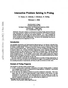
The scientist opens a browser window and launches the WBCSim Web page, which is dynamically generated from PHP and XML. The guest account is the default login option, which stores all the input and output data in a temporary directory that is purged periodically. The scientist selects the HC model from a list of all the available models by clicking “Use This Model as Guest”. The scientist then launches the HC model interface (Fig. 1) by clicking “New Hot Compression”. Here the scientist needs to specify the various input parameters for steering setup, material, initial condition, boundary condition, adhesive cure, and press schedule. Fig. 1 shows the press schedule menu along with a diagram to illustrate various definitions of press position vs. press time. The initial press closure time (PCT) can be specified there. The scientist can also define various model parameters for mat transport properties, boundary transport properties, and compression properties. The steering parameters won’t be available until the simulation is started. Finally, the scientist can specify the output styles, such as color or black and white, the time interval for generating frames for animation, and other parameters determining which data/image files are generated. Next, upon clicking the link “Run Simulation”, the input parameters (Boolean, numeric, or alphanumeric) are collected in the PHP code at the server as a long string (parameters are separated by white space). Then, the PHP module calls the HC model wrapper. Since the HC Fortran code has its own text-based user interface taking input from stdin, a temporary file is generated to contain all of the appropriate commands. Stdin is then redirected to this temporary data file for the simulation. The HC model wrapper then calls the HC Fortran code with this temporary file as stdin along with the properly formatted data file. When the simulation code is executing, the HC model wrapper monitors the simulation output stream for strings indicating execution milestones. The HC model wrapper uses the standard error stream for storing these messages into a log file, which a user can access from the log window (Fig. 3). When the simulation reaches the press closure time, the log window will come to the front and take the focus of the mouse. This prompts the scientist that it is time for steering. The scientist can then click the “Steering Parameters” link, which triggers a steering wrapper to take the intermediate result of the simulation and use Mathematica to plot density in the z-direction and adhesive effect in the z-direction (see Fig. 4). The scientist can enter a new press closure time and click the “Steer” button. This will terminate the existing simulation and start a new simulation with the new PCT. When the new simulation reaches this new PCT, the scientist can again enter the steering menu, which will plot the previous run along with the new simulation run to compare the effect of the two different PCTs. Fig. 4 shows a density plot of three iterations with PCT 15, 25, and 50. If the scientist is content with the current PCT, he can click the “Steer” button without entering anything; the steering wrapper will detect that there is no change, get out of the waiting loop and continue the simulation as usual. This is just one possible steering scenario involving the press schedule. When the simulation is complete and all the output data files are ready, the HC model wrapper calls Mathematica to read those data files and generate plots with various Mathematica commands such as ListContourPlot, ListPlot3D, MultipleListPlot, and Graphics3D. Mathematica also converts these internal graphics data structures into GIF format so that they can be viewed in a browser. Finally, the HC model wrapper embeds these GIF files in 13
HTML files and returns these HTML files to the PHP module. These HTML files are passed back to the client, where a user can click “View Results” to access them. Fig. 5 shows the final simulation results, which are the 3D profiles of temperature, moisture content, adhesive cure index, and total pressure, in animations.
8.
COMPUTATIONAL STEERING INSTANTIATION IN GENERAL
In summary, the set of changes and components required to provide a computational steering capability in WBCSim are: (1) design and add a very simple steering module at the legacy simulation code level, (2) provide a way to monitor simulation execution (alert users when it is time to steer), (3) add an interface to access and visualize simulation results, and perhaps to compare intermediate results across multiple steering attempts. In theory, the steering module can be written in any programming language corresponding to the legacy simulation code (Fortran 90 for WBCSim). This steering module can take a list of the steering setup parameters as inputs (number of iterations, maximum wait time, step wait time). The two nested loop logic is simple in concept. While the outer loop runs up to the number of iterations, the inner loop waits up to the maximum wait time per iteration. The inner loop checks if the steering input is present per stepwise wait time. If there is no steering input after the maximum wait time expires, or the steering input shows no change, the module will exit the inner loop and proceed to the next iteration. If the new steering inputs are different, the module should perform the steering by either exiting to start a new simulation with the new steering inputs (an abort/restart), or reset the steering parameters and continue the existing simulation run (normal steering). The choice of these two execution paths is completely dependent on the physics (fundamental science) and the organization of the legacy simulation code. For example, the legacy simulation code could have many arrays declared throughout various parts of the code with dynamic dimensions. These dimensions could be calculated on the fly based on various conditions. If the steering parameters affect the dimensions of these arrays, it may not be easy to deallocate and reallocate these arrays, since certain parts of the code may need to be executed again to calculate these dimensions. Therefore, instead of making massive changes to the legacy code to support steering, a steering module can simply allow a simulation to exit and restart. More importantly, adding steering requires significant collaboration between the PSE program developer and the domain scientists. That is because only the domain scientists fully understand the physics (fundamental science) and organization of the legacy simulation code. The domain scientists have to decide what parameters they would like to steer, what intermediate outputs and format they would like to see, and how to visualize such intermediate outputs. The domain scientists may need to pinpoint exactly where the steering module needs to be called in the simulation code and where the simulation needs to resume after the steering. It is very critical to provide a way to monitor the simulation execution, especially a time consuming simulation. In addition, a user needs to be informed or alerted when the steering time arrives. Depending on the run time of the simulation, a user may not monitor the progress of the simulation the entire time. The user may work on other things on the computer or not even at his desk. For the WBCSim HC model, a typical simulation run lasts from 45 minutes 14
to over an hour. Thus, the log window is sufficient as this log window would come to the front and take the focus when the steering time arrives. The mechanics of the log window is described in Section 6.1. The log window simply checks if there is any output from the steering module, and then pops to the front at the steering time. For longer simulations (say overnight simulations), other means should be considered such as email notification, or a predefined set of the steering inputs (different from a regular simulation run, since the legacy code may not have supported intermediate inputs). The number of iterations, maximum wait time, and stepwise wait time need to be calibrated accordingly based on the actual scenarios. A user needs an interface to access the intermediate results from the steering and steer the simulation if he chooses to. The intermediate results can be the raw data (data files) or visualizations (in 2D or 3D) or both. These results should provide meaningful clues for the user to determine the course of the simulation. It is very useful to be able to compare the intermediate results from several steering attempts (iterations). By examining these results, the user can apply his expert knowledge to steer the simulation to explore “what if” scenarios and potentially deepen his understanding of principles underlying the phenomenon. As effects due to changes in parameters become more instantaneous, the cause-effect relationships could become more evident. Section 7 describes the interface for the WBCSim HC model, which provides links to the actual data files for the intermediate results, plots comparing multiple steering iterations, and simple text fields to allow the user to specify new values for the steerable parameters. Depending on user needs and the computing environment, many creative steering interfaces can be designed and implemented. Obviously, a certain amount of work needs to be done to enable computational steering and add additional steering points. Also, there is execution overhead, as the simulation will run longer depending on the number of steering iterations, and the wait time per iteration. However, with the ability to change direction in the middle of the simulation, computational steering can effectively reduce overall computational time by reducing the number of nonproductive simulation runs, thereby making research more efficient, and possibly lead to new product designs from increased understanding of the physical phenomena being modelled. In general, computational steering has the potential to revolutionize computer simulation experiments by allowing scientists to interactively steer a simulation in time and/or space, and concentrate more on the science than on operating the computer. Computational steering supersedes the traditional simulation mode of many long running experiments, which may not produce the desired results; instead, it allows the scientist to be placed at the center of a computation and respond to simulation results as they occur by interactively manipulating the input parameters.
9.
FUTURE WORK AND CONCLUSIONS
While WBCSim can be developed on several different fronts: experiment management (EM), collaboration support, high performance computing, and XML integration [35] [33], the development track for computational steering intends to streamline the process of adding a steering point, add support for multiple steering points, and add database support. 15
9.1.
Streamline the Process of Adding a Steering Point
Currently, adding a steering point requires considerable work and interaction between a wood scientist and a program developer. The wood scientist needs to identify what parameters within a model simulation he would like to steer, when the steering would occur, what intermediate results he would like to see, in what format, and what the simulation behavior would be after steering (restart or continue with the new steered parameters). Then the program developer would insert such a steering module into the simulation code at the development level, and make the necessary interface changes at the interface level. A better approach would be standardizing the steering module so that a wood scientist could easily call such a steering module anywhere within the simulation code, and make the simulation code changes himself. Then, a wood scientist could simply alter the model specific XML sheet to change the interface to include a new steering point. 9.2.
Add Multiple Steering Points
There could be multiple steering points for a given simulation. For example, for the hot compression model, a wood scientist could be interested not only in the press closure time, but also in the gas pressure. The build-up of gas pressure inside the mat during the hot compression process must be carefully monitored to balance the conflicting goals of minimum time in the press and adequate cure of the adhesive. Most of the gas pressure is due to steam. The steam is useful early in the press cycle because it assists with heat transfer to the core of the mat. However, the gas pressure must be reduced before the press is opened, otherwise the rapid expansion will cause a rupture of the panel. It would be informative to see how the press closure time affects the gas pressure by using two steering points. This requires the ability to allow two steering points to interact with each other such as moving the execution of a simulation from one early steering point to a later steering point, or restarting from an earlier steering point (rather than restarting the entire simulation). 9.3.
Add Database Support for Computational Steering
The existing experiment management system can store either incomplete simulation inputs or a complete simulation run (both inputs and outputs). It would be useful to provide the ability to store intermediate results for computation steering. With this capability, a wood scientist could even compare one steering run (consisting of multiple simulation runs) to another steering run (consisting of other multiple simulation runs). Another user might also be interested in viewing or modifying an existing steering run. 9.4.
Conclusions
WBCSim has evolved steadily from a prototype PSE intended as a tool for computer science PSE research and a Web-based interface for a few legacy computer programs, to a manufactureoriented near commercial quality PSE that is seriously used by wood science researchers in industry and academia. Since interesting computational capabilities are still lacking [35], WBCSim will remain an object of computer science research for some time to come. 16
Yet the program’s interfaces, models, and output visualizations are now good enough to be used as production tools by wood scientists. The directions in which computer scientists would like to take WBCSim (collaboration, data mining, grid computing) are quite different from the directions that wood scientists would prefer for WBCSim (new models, refining existing models, more interface and visualization options). The present layered architecture of WBCSim supports these divergent development directions well. With the addition of a computational steering capability, WBCSim allows a wood scientist to interactively explore a problem gaining insight into the physical mechanisms being modeled, effectively reduce computational time, make research more efficient, and better pursue new product design. It allows the scientist to be placed at the heart of a computation, and apply his expert knowledge to respond to simulation results as they occur by interactively manipulating the model parameters. Moreover, the experience with WBCSim suggests that computational steering can be achieved in any PSE or any other computing environment embedded with legacy simulation code. The original stated goal [16] of WBCSim was to provide “an integrated set of facilities allowing wood scientists to concentrate on high-level problem solving rather than on low-level programming details and application scheduling/execution, allowing users to define, record, and modify problems, and visualize and optimize simulation results”. This goal is definitely closer when wood scientists are provided with a computational steering capability.
REFERENCES 1. Allen NA, Chen KC, Shaffer CA, Tyson JJ, Watson LT. Computer evaluation of network dynamics models with application to cell cycle control in budding yeast. IEE Systems Biology 2006; 153: 13–21. 2. Allen NA, Shaffer CA, Vass MT, Ramakrishnan N, Watson LT. Improving the development process for eukaryotic cell cycle models with a modeling support environment. Simulation 2003; 79: 674–688. 3. Ames AL, Nadeau DR, Moreland JL. VRML 2.0 Sourcebook, 2nd ed. John Wiley & Sons, Inc.: New York, NY, 1996. 4. Bramley R, Gannon D, Stuckey T, Villacis J, Akman E, Balasubramanian J, Breg F, Diwan S, Govindaraju M. The linear system analyzer. Technical Report TR-511, Dept. of Computer Sci., Indiana University, Bloomington, IN, 1998. 5. Brodlie KW, Mason S, Thompson M, Walkley M, Wood JD. Reacting to a crisis: benefits of collaborative visualization and computational steering in a grid environment. Proceedings of UK e-Science All Hands Conference: Sheffield, UK, 2002. 6. Brooke JM, Coveney PV, Harting J, Jha S, Pickles SM, Pinning RL, Porter AR. Computational steering in RealityGrid. Proceedings of the 22nd International VLDB Conference: Glasgow, England, 2003; 179–183. 7. Brooke J, Eickermann T, Woessner U. Application steering in a collaborative environment. Proceedings of Supercomputing 2003: San Francisco, California, USA. 8. Boisvert RF, Rice JR. Solving Elliptic Problems Using ELLPACK. Springer-Verlag: New York, NY, 1985. 9. Burnett T, Chaput C, Arrighi H, Norris J, Suson DJ. Simulating the Glast satellite with Gismo. IEEE Computing in Science and Engineering 2000; 2: 9–18. 10. Chen JX, Fu X. Integrating physics-based computing and visualization: modeling dust behavior. IEEE Computing in Science and Engineering 1999; 1: 12–16. 11. Dymond R, Lohani V, Kibler D, Bosch D, Rubin EJ, Dietz R, Chanat J, Speir C, Shaffer CA, Ramakrishnan N, Watson LT. From landscapes to waterscapes: a PSE for landuse change analysis. Engineering with Computers 2003; 19: 9–25.
17
12. Eisenhauer G, Gu W, Schwan K, Mallavarupu N. Falcon—toward interactive parallel programs: the online steering of a molecular dynamics application. Proceedings of The Third International Symposium on High-Performance Distributed Computing: San Francisco, California, USA, 1994. 13. Foster I, Voeckler J, Wilde M, Zhao Y. Chimera: A virtual data system for representing, querying, and automating data derivation. Proceedings of the 14th Conference on Scientific and Statistical Database Management: Edinburgh, Scotland, 2002; 37–46. 14. Geist GA, Kohl JA, Papadopoulos PM. CUMULVS: providing fault-tolerance, visualization and steering of parallel applications. International Journal of High Performance Computing Applications 1997; 11(3): 224–236. 15. Goel A, Baker CA, Shaffer CA, Grossman B, Mason WH, Watson LT, Haftka RT. VizCraft: a problem solving environment for aircraft configuration design. IEEE Computing in Science and Engineering 2001; 3: 56–66. 16. Goel A, Phanouriou C, Kamke FA, Ribbens CJ, Shaffer CA, Watson LT. WBCSim: a prototype problem solving environment for wood-based composites simulations. Engineering with Computers 1999; 15: 198– 210. 17. Goel A, Phanouriou C, Kamke FA, Ribbens CJ, Shaffer CA, Watson LT. WBCSim: a prototype problem solving environment for wood-based composites simulations. Technical Report TR98-25, Dept. of Computer Sci., Virginia Polytechnic Institute and State Univ., Blacksburg, VA, 1998. 18. Haber R, Bliss B, Jablonowski D, Jog C. A distributed environment for runtime visualization and application steering in computational mechanics. Computing Systems in Engineering 1992; 3(1–4): 501–515. 19. Ioannidis Y, Livny M, Gupta S, Ponnekanti N. ZOO: A desktop experiment management environment. Proceedings of the UK e-Science All Hands Meeting: Bombay, India, 1996; 274–285. 20. Jablonowski DJ, Bruner JD, Bliss B, Haber RB. VASE: the visualization and application steering environment. Proceedings of Supercomputing 1993: Tokyo, Japan, 1993. 21. Kumar S, Peters-Lidard C, Tian Y, Reichle R, Geiger J, Alonge C, Eylander J, Houser P. An integrated hydrologic modeling and data assimilation framework. IEEE Computer 2008; 41(12): 52–59. 22. Kamke FA, Wilson JB. Computer simulation of a rotary dryer: retention time. American Institute of Chemical Engineers Journal 1985; 32: 263–268. 23. Kamke FA, Wilson JB. Computer simulation of a rotary dryer: heat and mass transfer. American Institute of Chemical Engineers Journal 1985; 32: 269–275. 24. Liere RV, Wijk JV. CSE: a modular architecture for computational steering. Proceedings of Virtual Environments and Scientific Visualization 1996: Vienna, Austria, 1996; 257–266. 25. Mann V, Matossian V, Muralidhar R, Parashar M. DISCOVER: an environment for Web-based interaction and steering of high-performance scientific applications. Concurrency and Computation: Practice and Experience 2001; 13(8–9): 737–754. 26. McCormick BH, DeFanti FA, Brown MD. Visualization in scientific computing. Computer Graphics 1987; 21(6): 61–70. 27. Mishra D, Shaffer CA, Ramakrishnan N, Watson LT, Bae KK, He, Verstak A, Tranter WH. S 4 W : a problem solving environment for wireless system design. Software: Practice and Experience 2007; 37: 1539–1558. 28. Mulder J, Wijk JV, Liere RV. A survey of computational steering environments. Future Generation Computer Systems 1999; 15(1): 119–129. 29. Parker SG, Miller M, Hansen CD, Johnson CR, Sloan PP. An integrated problem solving environment: the SCIRun computational steering system. Proceedings of 31st Hawaii International Conference on System Sciences: (HICSS-31)-Vol. VII, Edited by H. El-Rewini, IEEE Computer Society, January 1998. 30. Rathmayer S, Lenke M. A tool for online visualization and interactive steering of parallel HPC applications. Proceedings of the 11th International Parallel Processing Symposium: Geneva, Switzerland, 1997. 31. Resnik J, Kamke FA. Modeling the cure of adhesive-wood bonds using high frequency energy. Final Report, U.S.-Slovene Joint Board on Scientific and Technological Cooperation, Project 95-AES10: Ljubljana, Slovenia: University of Ljubljana, 1998. 32. Rice JR, Boisvert RF. From scientific software libraries to problem-solving environments. Computing in Science and Engineering 1996; 3(3): 44–53.
18
33. Shu J, Watson LT, Ramakrishnan N, Kamke FA, North C. Unification of problem solving environment implementation Layers with XML. Advances in Engineering Software 2008; 39: 189–201. 34. Shu J, Watson LT, Ramakrishnan N, Kamke FA, Zombori BG. An experiment management component for the WBCSim problem solving environment. Advances in Engineering Software 2004; 35: 115–123. 35. Shu J, Watson LT, Zombori BG, Kamke FA. WBCSim: an environment for modeling wood-based composites manufacture. Engineering with Computers 2006; 21(4): 259–271. 36. Sioson A, Watkinson JI, Vasquez-Robinet C, Ellis M, Shukla M, Kumar Ramakrishnan N, Heath LS, Grene R, hevone BI, Kafadar K, Watson LT. Expresso and chips: creating a next generation microarray experiment management system. Proceedings of the Next Generation Software Workshop, 17th Internat. Parallel & Distributed Processing Symp.: Los Alamitos, California, USA, 2003. 37. Skidmore R, Verstak A, Ramakrishnan N, Rappaport TS, Watson LT, He J, Varadarajan S, Shaffer CA, Chen J, Bae KK, Jiang J, Tranter WH. Towards integrated PSEs for wireless communications: experiences with the S 4 W and SitePlanner projects. ACM SIGMOBILE Mobile Computing and Communications Review 2004; 8: 20–34. 38. Vanderplaats Research and Development, Inc. DOT Users Manual, Version 4.20. Colorado Springs: CO, 1985. 39. Vass M, Allen N, Shaffer CA, Ramakrishnan N, Watson LT, Tyson JJ. The JigCell model builder and run manager. Bioinformatics 2004; 20: 3680–3681. 40. Vass M, Shaffer CA, Ramakrishnan N, Watson LT, Tyson JJ. The JigCell model builder: a spreadsheet interface for creating biochemical reaction network models. IEEE/ACM Transactions on Computational Biology and Bioinformatics 2006; 3: 155–164. 41. Vetter JS, Reed DA. Real-time performance monitoring, adaptive control, and interactive steering of computational grids. International Journal of High Performance Computing Applications 2000; 14(4): 357–366. 42. Vetter J, Schwan K. Progress: a toolkit for interactive program steering. Proceedings of the 1995 International Conference on Parallel Processing: Urbana-Champain, Illinois, USA, 1995. 43. Vetter J, Schwan K. High performance computational steering of physical simulations. Proceedings of the 11th International Parallel Processing Symposium: Geneva, Switzerland, 1997. 44. Watson LT, Lohani VK, Kibler DF, Dymond RL, Ramakrishnan N, Shaffer CA. Integrated computing environments for watershed management. Journal of Computing in Civil Engineering 2002; 16(4): 259– 268. 45. Wolfram S. The Mathematica Book, 3rd ed.. Wolfram Media/Cambridge University Press: Champaign, IL, 1996. 46. Wood JD, Brodlie K, Walton J. GViz—visualization and steering on the grid. Proceedings of UK e-Science All Hands Conference: Nottingham, UK, 2003. 47. Zombori BG, Kamke FA, Watson LT. Simulation of the mat formation process. Wood and Fiber Science 2001; 33(4): 564–579. 48. Zombori BG, Kamke FA, Watson LT. Simulation of internal conditions during the hot-pressing process. Wood and Fiber Science 2003; 35(1): 2–23. 49. Zombori BG, Kamke FA, Watson LT. Sensitivity analysis of internal mat environment during hot-pressing. Wood and Fiber Science 2004; 36(2): 195–209.
19
Fig. 1. The HC model user interface.
20
Client Layer
Server Layer
Developer Layer
Web Interface (PHP)
11111111111111111111111111111111111111 00000000000000000000000000000000000000 Apache HTTP Server and PHP Module 00000000000000000000000000000000000000 11111111111111111111111111111111111111 00000000000000000000000000000000000000 11111111111111111111111111111111111111 0000000 1111111 0000000000000000 1111111111111111 0000000000000000 1111111111111111 0000000 1111111 VRML Translator HTML 0000000000000000 1111111111111111 0000000000000000 1111111111111111 0000000 1111111 Simulation 0000000000000000 1111111111111111 0000000 1111111 Mathematica Wrapper
1111111 0000000 0000000 1111111 0000000 1111111
XML
WhirlGif
111111111 000000000 000000000 111111111 000000000 111111111 Input Data 000000000 111111111 000000000 111111111
11111111 00000000 00000000 11111111 00000000 11111111 Results 00000000 11111111 00000000 11111111
111111111 000000000 000000000 111111111 000000000 111111111 SQL Query 000000000 111111111 000000000 111111111 Database
Simulation
Fig. 2. WBCSim architecture overview.
Fig. 3. The log window.
21
Fig. 4. The HC model steering interface.
22
Fig. 5. The HC model final simulation results: 3D profiles of temperature, moisture content, adhesive cure index, and total pressure, in animations.
23