CONCEPT OF A MEMS PROCESS SOFTWARE SPECIALLY DEDICATED TO THE DEEP X-RAY LITHOGRAPHY PROCESS Pascal Meyer, Joachim Schulz and Christian Solf Institut f¨ur Mikrostrukturtechnik Forschungszentrum Karlsruhe Postfach 3640, D-76021 Karlsruhe E-mail:
[email protected]
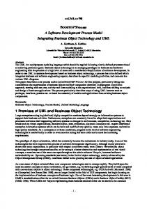
ABSTRACT Micro-electromechanical systems (MEMS) incorporate miniature electromechanical components fabricated with processing techniques and equipment originally developed for the semiconductor industry. Due to many processes employed for MEMS manufacturing originating in the semiconductor industry, silicon is typically utilized as a MEMS substrate; CAD tools for MEMS dedicated to bulk micromachining and semiconductor industry are commercially available (for example MEMS Pro from MEMSCAP). However, non silicon materials such as plastic and metal substrates are also emerging in microfabrication. The deep x-ray LIGA process, which combines X-ray lithography with electroplating and molding, is a technique used worldwide for the fabrication of high aspect ratio microstructures. Understanding device fabrication is essential in determining if an optimized device can be produced in a cost-effective manner using deep x-ray lithography process. Design and fabrication software tools are inadequate and unavailable. The concept of a general MEMS process physics simulation capability that addresses key process in the x-ray LIGA process is proposed here. INTRODUCTION Efficient manufacturing of MEMS using deep x-ray LIGA process (Hruby 2001) can be achieved by reducing the expensive and lengthy product development cycle times. In fact, manufacturing test structures is very expensive in terms of time and materials. When developing systems, the entire process from component specification to drawing preparation can be handled by the designer, but the specific fabrication techniques must be taken into account for the performance of the final system. For example, optical microsystem structures should be taken into account in the optical design stage as the optical performance can be influenced by these structures (Sieber et al. 2003). The final design should meet the requirements of the fabrication process. The LIGA technique (see Fig. 1), a German acronym consisting of the letters LI (R¨ontgen LIthographie meaning x-ray lithography), G (Galvanik meaning electroplating) and A (Abformung meaning molding) developed at the Karlsruhe Research Center , offers the possibility of manufacturing microstructures with high
aspect ratios, high accuracy from a variety of materials (metals, plastics and ceramics). A fabrication example is given in Figure 1. Deep x-ray lithography allows structures of any lateral design with high aspect ratios to be produced, i.e., with heights of up to 1 mm and a theoretical lateral resolution down to 0.2µ m. The walls of these structures are smooth and parallel. Very sophisticated structures of this type can be lithographically produced only by a highly penetrating, intense, and parallel synchrotron x-ray radiation. Our concept of a general MEMS process physics simulation capability that addresses key process in the x-ray LIGA process is represented in Figure 2. Process simulation includes: mask process, resist technology, irradiation and development steps, electroplating , rework, price, manufacturability, work plans. Design simulation includes: physical function of the component, process design rules. Design and fabrication software tools for LIGA process being inadequate and unavailable (Hahn et al. 2000), the central idea of this project is the creation of a process flow representation, which is a description that can be used for the tasks mentioned before: process design and simulation.
Layout
Irradiation
Electroplating, Rework, stripping
Working mask
Development
Etching, pick and place
Figure 1: A fabrication example to obain single metal parts
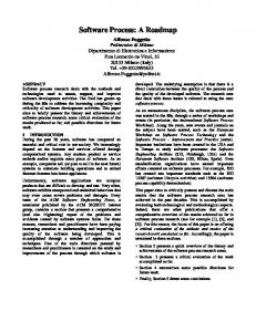
THE CONCEPT The LIGA process is composed of different steps each of which has its own requirements. How should my CAD design look, what kind of materials should the manufacturer use, what kind of mask process should we follow to fulfill customer specifications (roughness, feature, cost of the end product), how long will it take to obtain the product, what kind of resist should I use, which synchrotron beamline could I use, etc... ? A program named XLiGAProSim which could answer all these questions is under development. It will be composed of two modules: ✹ design simulation, ✹ process simulation which will compliment each other. The goal of this program is to offer the user a graphical user interface (GUI) specially dedicated to deep x-ray LIGA. A simple interface has been built for the process simulation (Figure 3). The user will be asked about his desired final product regarding its characteristic: cost, thickness, tolerance, material. The program will establish the best possible process . This will lead to design rules which must be applied for the design of the layout.
such as nickel, copper and gold, or alloys, such as nickelcobalt and nickel-iron, is generated. This technique is used to produce: ✹ microstructures for direct use, ✹ molding tools.
Customer‘s Asks
Concept for fabrication Process
Physical simulation (optics, mechanical...) Process Design rules
Figure 3: Prototype of the user interface of XLiGAProSim with the DoseSim module of the irradiation and development process step
Design
Cost Time planning
Fabrication
DESIGN SIMULATION The simulation includes the physical function of the component and the requirements of the fabrication process. Existing simulation software like ANSYST M , ZEMAXT M will be used to simulate the physical function and to establish and verify the layout, designed according to the design rules which will be given by the process simulation. For design rules checking, software like MEMSCAPT M (MEMSCAP 2002) exists but must be modified for the deep x-ray LIGA process.
Figure 2: Concept of the software PROCESS SIMULATION THE DEEP X-RAY LIGA PROCESS In the first step, the absorber structure of a x-ray mask is copied into resist layers by using synchrotron radiation. Usually, two types of resist material are used: poly(methylmethacrylate) (PMMA) and SU-8. In the case of the former, under exposure, the molecular weight decreases and it becomes soluble in a developer. In the latter case, there is a polymerisation and the unexposed part is soluble. The spaces generated by the removal of the irradiated plastic material can be filled with metal by electroplating processes. In this way, a negatively patterned secondary metal structure,
Design rules The x-ray design rules are a function of the final product. For example, special care should be taken in the design of auxiliary structures when the desired products are in metal (Solf et al. 2004). The purpose of the auxiliary structures are to minimize swelling and thermal expansion effects during the electroplating process, which may otherwise damage or destroy the LIGA structures. The auxiliary structures also promote equal current distribution during electroplating, which again leads, for example, to homogeneous nickel iron growth. The layout should be made as symmetric as possible, this is useful for internal stress compensation and subsequently reduces
the deformation of the LIGA structures. Also, differences in the process chain (synchrotron beam-line, type of resist ...) lead to dimensional differences between the CAD file and the end product. In order to yield the specified lateral dimensions, the CAD file has to be adjusted. The recent accumulation of manufacturing information is helping to implement these rules. For example the minimum size of one structure which could be obtained is different if this structure is positive or negative, and if the end product will be a mold or a single part in resist or metal. This size is also function of the mask process which will be used.
Mask process Different processes exist to produce the working mask, which its characterised by its membrane type and the thickness of the gold absorber. The type of working mask and its fabrication process is a function of the desired product. Two processes developed at FZK/IMT are implemented in the program.
Resist Technology Resist technology consist of applying a resist onto a substrate. The standard positive resist is PMMA. A database of resist technology is implemented, for example, the resist technology of FZK/IMT. The resist layer is fabricated by gluing a prefabricated, commercially available PMMA sheet (GS233 from R¨ohm GmbH) with polymerization glue onto the substrate. This process leads to adhesion characteristics which are known and implemented in the program.
Irradiation and development LIGA technology needs a synchrotron beam-line to perform the resist exposition and a scanner to move the sample. The mask and the substrate holder are one of the parameter of the process. Substrates could be: 4-inch wafer (Si, SiO2, Al2O3) which could be covered by a metal (Ti, TiOx, Au) or metal block (84x54x8mm). In the copy step of the LIGA process, the deposited dose calculations in the resist are needed. The basic calculii needed for synchrotron beam-line design are related to the spectra characteristics and to the modelling of the optical elements (mirrors, filters, beam-stop). For userfriendliness, a GUI (Graphical User Interface) working in a MS-Windows environment has been built (Meyer et al. 2003), which consists of one menu and different worksheets (see Fig. 3) which follow a LIGA beam-line design,e.g. the source, the optics (front-end window, mirror, filters), the scanning stage (mask, resist), the development process of the irradiated resist, and the time of irradiation. This program could be started directly with XLiGAProSim. For a given beam-line, the parameters of irradiation and development for a given mask and resist system is known. A database consisting of resist system (PMMA, SU-8) and synchrotron beam-line (ANKA, Bessy, Elsa) is implemented in the XLiGAProSim. For another resist system and synchrotron beamline, the GUI mentioned before can be used.
Electroplating Electroplating is the key step for the fabrication of metallic micro components. Established routine processes are often referred to by the plating solution. Typically every user performs the base processes with differences in electrolyte formulation and operation due to specific fabrication environments such as the plating apparatus. The parameters here are the desired thickness, the aspect ratio and material and its tolerances. A database taking into account these specifications is also implemented. If the thickness tolerances are too demanding for the electroplating process, some mechanical work such as polishing may be necessary. If the metal individual parts should be picked and placed, the type of etchant which should be used must be compatible with the type of material used.
Stripping This section concerns only PMMA because SU-8 stripping methods are not fully defined. The step consist to irradiated the PMMA and to dissolve it with ethyl-acetate. A database consisting of PMMA Thickness, synchrotron beamline (ANKA, Bessy, Elsa)) is implemented in the XLiGAProSim. CONCLUSION Process support specifically concerning the deep x-ray lithography is under development. The rules should need as little supplementary data as possible and rely basically in process, material and medium parameters. This software will offer these rules, design rules and the manufacturing infrastructure necessary for rapid product development and increased commercial success. REFERENCES Hahn K, Brueck R, Priebe A, Schneider C. 2000. ”Cost estimation for LIGA fabrication fl ows using process design methods” Microsystem Technologies 6, 4, 145-148. Hruby J. 2001. ”LIGA technologies and applications”, MRS Bulletin 26(4), 337-340. MEMSCAP 2002. ”MEMS Pro User Guide”. Meyer P, Schulz J, Hahn L. 2003. ”DoseSim: MS-Windows Graphical User Interface for using Synchrotron X-ray Exposure and Subsequent Development in the LIGA process”. Review of Scientific Instrument, 74 (2), 1113-1119. Sieber I, Hofmann A, Hollenbach U. 2003. ”Application of the microoptical construction kit to a microoptical sensor”.Proceedings MICROTEC 2003 (World microtechnologies congress, Munich,D, VDE Verlag GmbH, ISBN 3-8007-27919,381-386. Solf C, Janssen A, Mohr J, Ruzzu A and Wallrabe U. 2004. ”Incorporating Design Rules into the LIGA Technology applied to a Fourier Transformation Spectrometer”. to appear in Microsystem Technology.