Fusion Engineering and Design 109–111 (2016) 1335–1339
Contents lists available at ScienceDirect
Fusion Engineering and Design journal homepage: www.elsevier.com/locate/fusengdes
Conceptual design of a First Wall mock-up experiment in preparation for the qualification of breeding blanket technologies in the Helium Loop Karlsruhe (HELOKA) facility C. Zeile a,∗ , A. Abou-Sena a , L.V. Boccaccini a , B.E. Ghidersa a , Q. Kang a , A. Kunze a , L. Lamberti a,b , I.A. Maione a , J. Rey a , A. von der Weth a a b
Karlsruhe Institute of Technology (KIT), Hermann-von-Helmholtz-Platz 1, 76344 Eggenstein-Leopoldshafen, Germany Dipartimento Energia, Politecnico di Torino, Italy
h i g h l i g h t s • • • •
Experiment in preparation for the qualification of Breeding Blanket technologies in HELOKA facility is proposed. Experimental capabilities, instrumentation of the mock-up and experimental program are presented. Design and manufacturing of the mock-up is described. Design of modular attachment system to obtain different stress levels and distributions on the mock-up is discussed.
a r t i c l e
i n f o
Article history: Received 31 August 2015 Received in revised form 8 December 2015 Accepted 13 December 2015 Available online 13 January 2016 Keywords: Breeding blanket High heat flux Qualification HELOKA
a b s t r a c t An experimental program based on a First Wall mock-up is presented as preparation for the qualification of breeding blanket mock-ups at high heat flux in the Helium Loop Karlsruhe (HELOKA) facility. Two objectives of the experimental program have been defined: testing of the experimental setup and a first validation of FE models. The design and manufacturing of mock-up representing about 1/3 of the heated zone of an ITER Test Blanket Module (TBM) First Wall is discussed. A modular attachment system concept has been developed for the fixation of the mock-up in order to be able to generate different stress distributions and levels on the plate, which is confirmed by thermo-mechanical analyses. The HELOKA facility is able to provide a TBM relevant helium cooling system and to generate the required surface heat flux by an electron beam gun. An installed IR camera can be used to measure the temperature distribution on the surface. © 2016 Published by Elsevier B.V.
1. Introduction The current designs of the European helium cooled breeding blanket concepts for the Test Blanket Module (TBM) program in ITER as well as for the installation in DEMO consist of complex box architectures with a high pressure zone for the coolant and a low pressure zone for the tritium breeder. The box design is characterized by a high number of cooled subcomponents with integrated cooling channels. The supply of the coolant is realized by a multistage distributor and collector system. The integral analysis of this complex structure is beyond the capabilities of present numerical simulation and the used models are still under development [1]. For instance, this applies in the case of the EU Helium Cooled Peb-
∗ Corresponding author. Tel.: +49 07247 82 22473. E-mail address:
[email protected] (C. Zeile). http://dx.doi.org/10.1016/j.fusengdes.2015.12.031 0920-3796/© 2016 Published by Elsevier B.V.
ble Bed (HCPB) concept for the thermo-mechanical behavior of the pebble beds as well as the thermal properties of the bonding of the first wall coating under cyclic loading. Consequently, the qualification of such a component based on numerical analyses can be difficult if too conservative assumptions have to be made. At the Karlsruhe Institute of Technology (KIT) an experimental program with mock-ups of different sizes is foreseen in the Helium Loop Karlsruhe (HELOKA) facility [2,3] to support the development of the implemented models. Since the HELOKA facility is able to provide ITER relevant operating conditions, it also qualifies the facility for the application for the design validation by the design-by-experiments method as covered for plasma facing components by the Structural Design Criteria for In-vessel Components (SDC-IC) code [4]. As a first step in preparation toward the experimental program in HELOKA, a First Wall Mock-up (FWM) is planned to be tested in the facility. The FWM, whose design and manufacturing is
1336
C. Zeile et al. / Fusion Engineering and Design 109–111 (2016) 1335–1339
Table 1 Operational range of HELOKA. Parameter
Range
Pressure Temperature Flow rate
4–9.2 MPa 70–500 ◦ C 0.4–1.4 kg/s
discussed in Section 3, represents about 1/3 of the heated zone of the TBM First Wall. Two main objectives for this preparation step have been defined: (a) testing of instrumentation, data acquisition and components of the experimental setup; (b) validation of FE models used in the analysis of the breeding blanket concepts. Part of the first objective is the development and testing of an instrumentation concept that would allow the measurement of temperatures and strains on the mock-up. This includes the selection of sensor technologies as well as finding a suitable installation concept. In addition, the capability to generate the required heat flux pattern by the installed electron beam gun as well as the overall performance of the experimental setup under a high number of cycles has to be demonstrated. The second objective comprises the validation of thermohydraulic and thermo-mechanical models for specific thermal and mechanical boundary conditions. While the thermal boundary conditions can be adjusted during the testing, for example, by regulating the mass flow of the coolant or changing the settings or the scanning pattern of the electron beam gun, the mechanical boundary conditions remain fixed and are strongly depending on the attachment of the mock-up to the supporting structure. In Section 4, a modular attachment system for the FWM that is able to represent two different types of fixation is introduced and discussed.
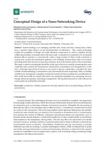
The initial testing has indicated that, at high power levels, the footprint of the scanning pattern has the tendency to rotate by a certain angle as it can be seen in Fig. 1. Currently studies for quantifying and compensating this effect are ongoing. In addition to that, the installation of an infrared camera (X6580sc from FLIR) is performed. This camera has an IR resolution of 640 × 512 with a maximum image frequency of 355 Hz for the full frame. However, the accuracy of the temperature measurements of the IR camera depends on the precise knowledge of the emissivity of FWM plate as well as the influence of reflections inside the vacuum chamber. For this reason, a dedicated calibration step is foreseen making use of the water-cooled dummy. For this purpose, thermocouples will be installed on the surface of the dummy to measure the temperatures at different power levels.
2. Testing in HELOKA facility
2.2. Instrumentation of the FWM
The experiments will be performed in the HELOKA facility, which is able to provide ITER relevant helium cooling conditions and representative surface heat fluxes. The experimental capabilities of HELOKA and the instrumentation of the FWM are described in Sections 2.1 and 2.2, respectively. The testing program is discussed in Section 2.3.
The physical quantities, which need to be measured on the FWM to validate the models and the results obtained by the FE analyses, are temperature and strain. Given the operating conditions of the TBM the sensors mounted on the mock-up will have to withstand high temperatures up to 500 ◦ C and the energy deposition by the electron beam on the top side has to be considered. In the case of wall surface temperature the infrared camera will be used. The camera is installed outside the vacuum chamber and looks at the top side of the mock-up via a mirrors system, which will be tested and qualified when the camera is calibrated. For other temperature measurements, thermocouples will be used. Although a number of electrical resistance strain gauges are available that are able to work within the required temperature range, the lower thermal conductivity of the bonding material or the small contact area in case of spot welding has to be carefully considered when placing the strain gauges on the heated surface. In order to avoid this issue, only a placement of strain gauges on the top side outside the heated zone as well as on the lateral faces is foreseen.
2.1. Experimental capabilities of HELOKA The operational range of the experimental loop is listed in Table 1. The experimental loop can be connected to two test sections, each one consisting of a 30 m3 vacuum chamber that is able to accommodate a full-size TBM. The associated vacuum systems can generate and maintain a vacuum level of 10−5 mbar inside the chambers. One of the vacuum chambers is equipped with an electron beam gun that has a maximum installed power of 800 kW and is capable to generate a TBM relevant surface heat flux of 0.5 MW on a surface of approx. 0.8 m2 by guiding the beam in an appropriate pattern. The other test section uses infrared (IR) radiation heaters that can generate similar surface heating conditions [5]. While the capabilities of such a solution have been demonstrated in a separate experiment, the limited life time of the heaters has determined the selection of the EB gun test section as the first option for the FWM experiment. In order to calibrate the electron beam gun and set-up an appropriate scanning pattern to produce a homogenous heat flux with a TBM relevant peak heat flux, a water-cooled dummy target with the dimensions of the TBM First Wall is installed in HELOKA (see Fig. 1). The target is made of steel P92 (1.4901), the same material used for the FWM.
Fig. 1. Experimental setup with water-cooled target.
2.3. Experimental program Two objectives of the experimental program have been defined in Section 1: testing of the experimental setup and validation of FE models. During the experimental program, two types of fixation for the FWM are foreseen: one fixation that allows an almost free deformation of the plate (F1) and one fixation that strongly limits the deformation normal to the surface receiving the heat load (F2). Hence, F1 enables to vary the surface heat flux in a wide range, whereas a high stress level and a different stress distribution on the plate can be achieved with F2.
C. Zeile et al. / Fusion Engineering and Design 109–111 (2016) 1335–1339
1337
Fig. 3. Transparent view of FWM with inserts. Fig. 2. Top view of the FWM plate after spark eroding.
The temperature and strain data recorded during experiments with F1 and different thermal boundary conditions (heat flux, inlet temperature, mass flow) will be used to validate the FE models applied in the thermo-hydraulic and thermo-mechanical analyses. In contrast to the temperature measurement by the IR camera, strains can only by measured at certain points on the structure. For this reason, the limited number of strain gauges has to be placed in such a way that these points are representative for a strain distribution, which can be compared to results of the thermo-mechanical analyses. In the second part of the experimental program, the attachment configuration is changed to F2 in order to generate a strain distribution and level different from F1 on the plate. The comparison of the two different strain distributions will facilitate the validation of the FE models. 3. Design and manufacturing of the FWM The FWM has the dimensions of 710 mm × 405 mm × 45 mm as indicated in Fig. 2. Therefore, its dimension perpendicular to the cooling channels is close to the toroidal dimensions of 484 mm of the First Wall of an EU ITER TBM [6] and hence represents about 1/3 of the heated zone of the TBM First Wall. The 10 U-shaped rectangular cooling channels have the same dimensions as the First Wall cooling channels of the TBM: a cross section of 15 × 15 mm, wall thickness between the channels of 5 mm and wall thickness to the heated surface of 3 mm. The connections of each channel to the loop are provided by a pipe parallel and a pipe perpendicular to the channels with an inner diameter of 8 mm. The FWM is made of steel P92 (1.4901), which has comparable material properties to the reduced activation ferritic–martensitic (RAFM) steel Eurofer used for the TBM. The outer geometry of the plate is fabricated by water jet cutting and milling. The channels have been manufactured by spark eroding and the U-turn is realized by appropriately shaped inserts (Fig. 3). These inserts are welded into corresponding pockets by electron beam (EB) welding. A horizontal (parallel to the channel) and a vertical tube with Swagelok connector for each channel represent the connection to the experimental loop. The horizontal tubes are part of the end cap inserts. The vertical tubes are welded to the FWM plate by TIG welding. The FWM plate is shown in this manufacturing status without Swagelok connectors in Fig. 4. The final fabrication step is the manufacturing of the connection interface to the attachment system.
expansions of parts of the structure with different temperatures cause internal stresses. Second, the attachment system hinders the free expansion of the plate. These two effects can be used to influence the stresses distribution and level on the FWM. For this reason, a modular attachment system concept has been developed that allows a method of fixation for an almost free expansion of the plate (F1) as well as a method that limits the deformation normal to the top surface (F2). The modular design for the attachment system additionally reduces the time for the modification. Two important aspects have to be considered for the design of the attachment system. One purpose of the attachment system is to achieve a TBM relevant stress level on the FWM during the experimental program. However, on the other hand, the limits given by the design code RCC-MRx [7], which is relevant for the TBM, must not be exceeded by two types of fixation F1 and F2 at any time. Therefore, a range of possible thermo-hydraulic boundary conditions has to be defined individually for each type of fixation. The thermal boundary conditions, which can be adapted independently of the fixation, are defined in Section 4.1, whereas the mechanical boundary conditions are described together with the design of the attachment system in Section 4.2. 4.1. Thermal boundary conditions The thermal boundary conditions consist of the surface heat flux on the top side of the FWM plate generated by the electron beam gun and the thermo-hydraulic boundary conditions given by the coolant helium. For each type of fixation, an individual experimental domain has to be defined in order to respect the rules given by the design code and not to risk damaging the FWM. Nevertheless, in the following, a reference case is defined for the thermo-mechanical analyses presented in Section 4.3 that corresponds to the boundary conditions of the TBM in ITER. The surface heat flux generated by the electron beam represents the thermal load coming from the plasma. Therefore, the reference heat flux is defined as the maximum peak heat flux on the
4. Attachment system of the FWM The main part of the stresses on the FWM results from the effects due to the thermal expansion of the plate. First, the unequal thermal
Fig. 4. Bottom view of the FWM mock-up.
1338
C. Zeile et al. / Fusion Engineering and Design 109–111 (2016) 1335–1339
Fig. 5. Temperature distribution in ◦ C on the surface of the FWM for the reference case. Fig. 7. Attachment configuration 2 (F2).
TBM of 0.5 MW/m2
during the plateau phase of a typical ITER pulse according to [8]. The coolant helium in each channel is specified with an inlet temperature of 300 ◦ C at a pressure of 8 MPa and mass flow of 0.09 kg/s. Due to the U-shape of the channels, each channel has a cold and hot leg. The inlets and outlets are defined in such a way that the arrangement of the cooling channels represents a hot–hot/cold–cold pattern corresponding to the HCPB TBM. The temperature distribution on the top side of the FWM for this reference case is given in Fig. 5 with the indicated area of the applied homogenous surface heat flux of 0.5 MW/m2 .
4.2. Design and mechanical boundary conditions The mechanical loads on the FWM are given by the pressure of the helium of 8 MPa inside the channels and the deadweight of the plate. Two different mechanical boundary conditions are given by the types of fixation F1 and F2 of the attachment system. F1 has been realized with a central fixation of the plate in combination with flexible elements. Twelve pins with a diameter of 10 mm and length of 100 mm are screwed to the back side of the plate in a circular arrangement around the center of the plate. The pins are attached by a bolted connection on the opposite side to a ring, which represents the interface to the experimental supporting structure. A ceramic washer is foreseen between the pins and the ring in order to decouple them thermally and to obtain clearly defined boundary conditions. F1 is schematically shown in Fig. 6. For F2 the central element of F1 is kept and a rectangular frame is additionally mounted on the experimental supporting structure below the FWM. In order to restrict the deformation normal to the surface, the plate rests on 6 blocks fixed to the frame by a bolted connection. The part of the blocks in contact with the plate will be made of an insulating material, e.g. zirconium dioxide (ZrO2 ). The blocks are marked with circles in Fig. 7.
Fig. 6. Attachment configuration 1 (F1).
4.3. Results of the thermo-mechanical analyses Thermo-mechanical analyses of the attachment configurations F1 and F2 have been carried out with the FE software ANSYS to check if the two configurations fulfill the requirements in terms of mechanical boundary conditions. In addition, the results of the analyses have been used to evaluate the design according to the design rules given by the RCC-MRx code. The comparison of the deformation of the plate between the two attachment configurations shows that F2 is able to significantly reduce the deformation in z-direction normal to the surface for the reference case defined in Section 3.1. Due to the higher temperature at the top side of the plate of about 450 ◦ C in contrast to about 300 ◦ C at the back side, the FWM tries to bend, as clearly noticeable in Fig. 8 for F1. Hence, the deformation in negative z-direction of the FWM with F1 with −1.048 mm is significantly greater than the deformation of −0.060 mm with F2. The restriction of the deformation due to F2 results in a different stress level and distribution in comparison to F1 on the FWM. This desired effect is visible in Fig. 9, where the von Mises stresses on the top side are compared for both configurations. F2 leads to a higher stress level and a stress concentration in the center of the plate. In order to evaluate the stresses according to the design code RCC-MRx, a number of critical paths have been defined on the model. For these paths, the compliance of the design with the rules against monotonic and cyclic damages has been checked. For the rules against creep and cyclic damage the operating time (850 h) and cycles (3000 cycles/year, 2.5 years of operation) of the TBM in ITER have been taken as reference. F1, which allows an almost
Fig. 8. Deformation of the FWM plate in z-direction in mm with F1 (top) and F2 (bottom) for the reference case.
C. Zeile et al. / Fusion Engineering and Design 109–111 (2016) 1335–1339
Fig. 9. Von Mises stresses in MPa on the surface of the FWM with F1 (top) and F2 (bottom) for the reference case.
free deformation, fulfills all the criteria specified by the design code for the reference case. In contrast, F2 does not fulfill the criterion defined by the rule against progressive deformation. Nevertheless, the design of F2 is still suitable for the application as the purpose of F2 is to produce a stress level close to the design limits. However, in order to ensure a safe operation of the mock-up during the experiments, F2 has been evaluated at lower heat fluxes as well. This evaluation has shown that a reduction of the heat flux to 0.4 MW/m2 is sufficient to fulfill the criteria given by the design code with F2. 5. Conclusion This paper presents an experimental program based on a First Wall mock-up (FWM) in preparation for the qualification of breeding blanket mock-ups at high heat flux in the HELOKA facility. The design and the actual state of the production of the FWM have been described. The next step is the manufacturing of the connection interface to the attachment system. As the design of the attachment system has a major impact on the stress distribution on the FWM, a modular attachment system has been proposed in order to be able to generate different stress levels and distributions. The first type of fixation (F1) allows an almost free thermal expansion of the
1339
plate, whereas the second one (F2) restricts the deformation normal to the surface. Thermo-mechanical analyses have confirmed that the FWM with F1 can withstand a TBM relevant surface heat flux of 0.5 MW/m2 and in the case of F2 a maximum heat flux of 0.4 MW/m2 can be applied. The experimental program will be performed in the HELOKA facility, which is able to provide a TBM relevant helium cooling system and to generate the required surface heat flux by an installed electron beam gun. Furthermore, the vacuum chamber is equipped with an IR camera to measure the temperature distribution on surface of the FWM. Additional measurements of temperature and strain are obtained by thermocouples and strain gauges attached to the plate. Two objectives of the experimental program have been defined: Testing of the experimental setup and validation of FE models. In order to achieve these objectives a high number of cycles with the maximum heat flux of 0.5 MW/m2 will be conducted with F1 to demonstrate the long-term stability of the setup. In a second step, the attachment will be changed to F2 in order to obtain a different stress level and distribution on the FWM. Finally, the recorded temperature and strain data will be used to validate the FE models. Finally, by this experimental program it will be possible to gain important experiences in the qualification of breeding blanket mock-ups under relevant thermal-hydraulic conditions. References [1] Y. Poitevin, L.V. Boccaccini, M. Zmitko, I. Ricapito, J.-F. Salavy, E. Diegele, F. Gabriel, E. Magnani, H. Neuberger, R. Lässer, L. Guerrini, Tritium breeder blankets design and technologies in Europe: development status of ITER test blanket modules, test & qualification strategy and roadmap towards DEMO, Fusion Eng. Des. 85 (10–12) (2010) 2340–2347. [2] B.E. Ghidersa, V. Marchese, M. Ionescu-Bujor, T.H. Ihli, HELOKA facility: thermo-hydrodynamic model and control, Fusion Eng. Des. 83 (10–12) (2008) 1792–1796. [3] B.E. Ghidersa, M. Ionescu-Bujor, G. Janeschitz, Helium Loop Karlsruhe (HELOKA): a valuable tool for testing and qualifying ITER components and their He cooling circuits, Fusion Eng. Des. 81 (8–14) (2006) 1471–1476. [4] G. Sannazzaro, V. Barabash, S.C. Kang, E. Fernandez, G. Kalinin, A. Obushev, V.J. Martínez, I. Vázquez, F. Fernández, J. Guirao, Development of design criteria for ITER in-vessel components, Fusion Eng. Des. 88 (9–10) (2013) 2138–2141. [5] André Kunze, Bradut-Eugen Ghidersa, Flavia Bonelli, SIRHEX—a new experimental facility for high heat flux testing of plasma facing components, Fusion Eng. Des. (2015) (in press). [6] M. Zmitko, J. Galabert, N. Thomas, L. Forest, P. Bucci, L. Cogneau, J. Rey, H. Neuberger, Y. Poitevin, The European ITER test blanket modules: current status of fabrication technologies development and a way forward, Fusion Eng. Des. (2015) (in press). [7] Afcen (French association for design, construction and in-service inspection rules for nuclear island components), Design and Construction Rules for Mechanical Components of Nuclear Installations (RCC-MRx), 2012. [8] F. Cismondi, G. Aiello, S. Kecskes, G. Rampal, Thermomechanical performance of the EU TBMs under a typical ITER transient, Fusion Sci. Technol. 60 (1) (2011) 123–127.