Content-based Image Retrieval algorithm Acceleration in a Low-cost Reconfigurable FPGA Cluster C. Pedrazaa,∗, E. Castillob , J. Castilloa,∗, J.L. Bosqueb , J.I. Martineza , O. D. Roblesa , J. Canoa , P. Huertaa a
Universidad Rey Juan Carlos, DATCCCIA, Escuela T´ecnica Superior de Ingenier´ıa Inform´ atica, M´ ostoles Madrid, 28933, Spain. b Universidad de Cantabria. Facultad de Ciencias. Dpto. de Electr´ onica y Computadores. Santander, Spain.
Abstract The SMILE project main aim is to build an efficient low-cost cluster based on FPGA boards in order to take advantage of its reconfigurable capabilities. This paper shows the cluster architecture, describing: the SMILE nodes, the high-speed communication network for the nodes and the software environment. Simulating complex applications can be very hard, therefore a SystemC model of the whole system has been designed to simplify this task and provide error-free downloading and execution of the applications in the cluster. The hardware-software codesign process involved in the architecture and SystemC design is presented as well. The SMILE cluster functionality is tested executing a real complex Content Based Information Retrieval (CBIR) parallel application and the performance of the cluster is compared (time, power and cost) with a traditional cluster approach. Key words: FPGA, Content based image retrieval, Cluster 1. Introduction The last two decades have seen the great impact that Commodity Offthe-Shelf (COTS) clusters and open source software have had in High Performance Computing (HPC). However, todays technology face serious problems to be able to scale up with the computing problems that can get even worse. ∗
Email:
[email protected] (C. Pedraza),
[email protected] (J. Castillo)
Preprint submitted to Journal of Systems Architecture
April 27, 2010
Power consumption, heat dissipation and integration at all levels can be the biggest challenges of the next generations of supercomputers. High Performance Reconfigurable Computing (HPRC) arrived as a new approach that put together the best of two worlds: the hardware design on FPGAs and the parallel processing [1] [2]. This new approach has the ability to combine both the parallelism of tasks and data coarse-grain, as well as the instruction level on-FPGA fine-grain [3]. This has to be true when all the major players in high performance systems have developed these type of products (for instance the SGI RASC100 [4] or the Cray XD1 [5]). One of the main drawbacks of these products is the high price per unit. This paper details a new HPRC architecture proposal from the SMILE (Scientific Parallel Multiprocessing based on Low Cost Reconfigurable Hardware) project, as well as a new framework for developing applications with commercial FPGA boards [6]. This HPRC architecture tries to take advantage of all the FPGAs capabilities, including the Hard Core Processors (able to run OS like Linux). In this way, SMILE can combine parallelism and distributed memory with a cluster of FPGA-based reconfigurable hardware. Other important distinctive characteristics of the SMILE proposal are the low power consumption, the scalability, the low cost of the FPGA and the small space required for the cluster. Another important commitment of the project is the code portability: SMILE is able to run any parallel application based on the MPI library. This allows these applications to migrate without changing anything in terms of communications and to easily change the computationally challenging software tasks for their equivalent hardware tasks in order to improve the performance. There are similar approaches in the literature. For example, the RCC (Reconfigurable Computing Cluster) project studies the economic viability of FPGA-based clusters [7] [8] [9]. AFRL Rome project built the first heterogeneous computer based on FPGAs [10], with a cluster with the reconfigurability of adaptive computing systems into a 48 node heterogeneous high performance computer (HHPC). Cathey et al [11] proposed reconfigurable data-flow architecture interconnected with a scalable network, able to exploit fine and coarse grain parallelism through the use of a data-flow processing model. Also it has a linear interconnect scalability through the use of a direct network, and the ability to reuse pre-compiled processing elements through the use of pre-computed PE/PN lookup tables. The RAMP (Research Accelerator for Multiple Processors) project works on the definition of the next generation of software and hardware tools to research in computer architec2
ture [12]. This project uses a custom platform named Berkeley Emulation Engine 2 (BEE2), that provides a large amount of FPGA fabric, DRAM memory, and high bandwidth I/O channels on one board. Another example is the Cube Project [13] that presents a 512 FPGA cluster made up of eight boards with 64 FPGAs each, suitable for large scale parallel applications, like massively parallel cryptographic key crackers, stochastic Cellular Automators (SCA), physics or financial simulations. COPACOBANA is another parallel architecture based in 120 low-cost FPGAs and is able to perform an exhaustive key search of the Data Encryption on different algorithms [14]. Finally, Interconnect Systems Inc. [15] has the Nallatech FPGA Accelerated Computing series with two Xilinx Virtex-5 FPGAs LX330T, SX240T or FX200T, an 1x Intel Xeon processor and four banks of DDR-II SRAM memory. Other tools and techniques has been developed for aiding the speedup of tasks applications with FPGAs, for example El-Araby et al [1, 16] proposes virtualization where they use partial runtime reconfiguration for switching the different hardware functions programmed in the FPGA, therefore multiplexing the FPGA resources along the time. These kind of tools allow to the designer anticipate the reconfigurable behavior of the system, FPGA resources etc. What makes the SMILE Project different from the other approaches is that SMILE provides a whole framework to develop parallel applications that use well-established standards like MPI and a communication infrastructure for the cluster nodes that increases the usability of the cluster [17]. A semiautomatic design flow using SystemC was developed for helping in the design flow over SMILE. The functionality has been tested on a real complex Content-based Information Retrieval (CBIR) parallel application (search and retrieve of multimedia data based on their own content [18]) and the performance of the cluster has been compared (time, power and cost) with a traditional cluster approach. The results have confirmed our theoretical expectations. 2. Content-Based Image Retrieval. The content-based image retrieval is an application of computer vision for the problem of searching digital images in large databases. To find an specific image is necessary to compare it to every single one of the database images. This comparison requires a computational effort that when apply to
3
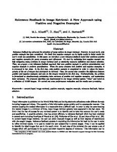
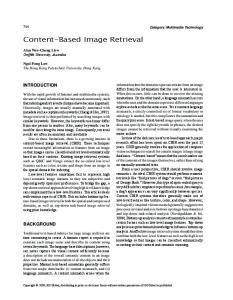
long databases implies a great amount of time. Acording to the Yoo et al. [19] definition of Content-based Image Retrieval (CBIR): Let the N images in the database be X = x1 , . . . , XN . Each image xi will have an associated feature vector fi which contains the relevant information required for measuring the similarity between images. Let N feature vectors associated with N images be F = f1 , . . . , fN . Let T represent a mapping from the image space onto the n-dimensional feature space, fi , i.e., T : x → f , where x ∈ X and f ∈ F . The similarity between two images xi and xj can be measured using similarity function d(fi , fj ) which describes the distance between the feature vectors, fi and fj . The choice of this similarity function is critical and domain-dependent. The problem of retrieval can then be posed as follows: Given a query image, q retrieve a subset of images M from the image database X = x1 , . . . , xN , M ⊂ X such that d(T (q), T (m)) ≤ t, m ∈ M where t is a user-defined threshold. Wavelet transforms, and specially the Haar transform, have become a powerful tool in object recognition. They can be seen as a reformalization of multiresolution methods from the 80’s [20, 21]. The information they provide is quite similar to the one obtained from Fourier-based techniques, but taking advantage of working with local information and using base functions with compact support. Wavelet transform coefficients show variations in object features at different resolution or scale levels ([22–24]). Roughly speaking, detail coefficients of the wavelet transform of an image can be considered as a contour extraction process of the objects appearing on it, while analysis coefficients behave in a different way: the lower the resolution level, the more homogeneous the regions they produce. An example is shown in Figure 1. To represent the color information of the original image at different resolution levels, the energy of the analysis coefficients (labelled “A” in Figure 1) and the diagonal detail ones (labelled “D” in Figure 1) has been computed, since the energy remains invariant at each resolution level. The associated feature vector, called signature is then the result of linking together the energy values from all resolution levels and considered regions. Additionally, working in RGB color space means to apply this process over each one of the color planes of the image. The whole process results in a vector of 42 elements. Then, the similarity function chosen is a minimum distance classifier based on Euclidean distance. Further details can be found in [25].
4
A
H
A
V
H
D
V
D
A V H D
Figure 1: Non-standard transformation of an image.
3. The SMILE Cluster Architecture SMILE cluster is made up of 32 FPGA nodes and a host computer monitoring the cluster operation and sharing its hard disk through the net providing storage to the nodes. Currently each node consists of a Diligent XUPV2P Board. This board has been selected for its low price, low power consumption and high performance. The board includes a Xilinx V2P30 FPGA with two PowerPC 405 microprocessors, and 8Multi-Gigabit transceivers that are used for the boards high speed communication. The hardware implemented in the FPGA logic can be connected to the PowerPC processor through the on-chip peripheral bus (OPB). The board also contains the peripherals needed to develop complex applications like DDR-SRAM controller, System ACE controller (for compact flash memories) and RS232 interface. With all these elements it is possible to run a complete Linux kernel inside the PowerPC microprocessor, using all the programs and libraries available for this operating system. The main tool needed for the SMILE Cluster is a MPI implementation that allows managing the cluster communication using a standard API. For the initial versions of SMILE we used a standard MPI 5
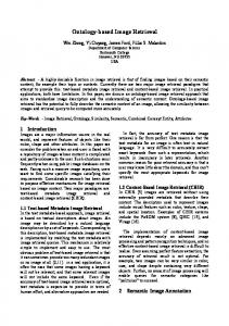
implementation, more precisely LAM/MPI, which is freely available in the web. The overhead introduced by this version of MPI was unacceptable (in the order of 46 seconds only to execute the processes remotely in all the nodes. Due to that problem we have developed our MPI implementation called SMPI. It is a lightweight implementation of the MPI standard. The SMPI library offers the possibility of sending the data between the nodes using the Ethernet connection or through the Rocket IOs included in the board. 3.1. Network The network is a critical point for any parallel architecture. The Ethernet network interface provided by Xilinx is not fast enough to support cluster communications, so this network interface is used only used for management tasks. The Diligent XUP-V2Pro board includes three SATA sockets connected to the FPGA Multi Gigabit Transceivers (MGT) to support high speed communications. The management of these transceivers is simplified by using the Aurora core provided by Xilinx. This core is able to send and receive data up to 10Gbps through a serial interface, but in the Digilent board this speed is limited to 1.5Gbps. This communication channel can now be use in the SMILE Cluster thanks to the new interface developed for the Aurora Core and the Linux operating system. The developed interface, called SMILE Communication Element (SCE), has two goals: 1) appear as a conventional network resource in Linux and make the use of the core from the SMPI library easier, and 2) provide network routing between the boards. The SCE hardware decides the route to be followed by the packet to reach its destiny. As shown in figure 2, the SCE has the following elements: • Three Aurora cores provided by Xilinx, one for each communication interface. Since the board has three connectors, the SCE includes one Aurora core for each one to manage the data exchange on that link. • Send and Receive FIFOs to store the packets to be sent and received. The SCE has three FIFOs for each Aurora core, therefore nine FIFOs. One FIFO stores the data to be sent, another one stores the received data for the current node and the last one is a buffer that stores the data to be routed to a different node when is busy.
6
OPB Bus
Bus Controller
Routing Controller
Aurora Core 1
Aurora Core 2
Aurora Core 3
MGT
MGT
MGT
Figure 2: SCE architecture.
• Logic to take the routing decisions and the data exchange between the three Aurora cores. The routing algorithm selects what would be the channel to route the data to the appropriate destination. There is a hierarchical network topology with all the nodes in groups of four, called SMILE Block Element (SBE). Every node in the SBE is connected to its SBE neighbors with a bidirectional channel. In this hierarchical fashion, every SBE is connected to its neighbors, so their respective nodes can communicate to each other. Therefore, an SMILE cluster of 32 nodes has a network length of 13 steps. The routing for this topology is quite straightforward. If the package destination is in the working node, the processor delivers. If not, the SCE selects which of the other two interfaces is the appropriate to use. When the destination is in the same SBE, the address can be smaller that the working node, so the package is sent back to the previous neighbor, or higher, so the package is sent to the next node. When the destination is in a different SBE, the data goes to the next SBE neighbor to carry on to its final destination. All the information needed by the routing algorithm (working node address, neighbors, SBE neighbor, etc.) is set up in the SCE by the Linux driver during the system start-up. 4. Modeling SMILE cluster in SystemC. Developing and debugging a SMILE application is a hard task because there is not an available standard way to simulate the whole system with all its interactions. In order to simplify the development of SMILE applications 7
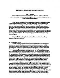
a SystemC framework has been developed to let us simulate the whole cluster with the associate hardware running in parallel. The main idea is to start with a high level model of the system and refine it down to the final design that will be implemented on the nodes. In the SMILE application context, the entry point is a parallel application using an MPI library that needs to be accelerated by custom hardware. These are the step to get to a synthesizable model of the system: • Development of a SystemC model of the system for the cluster from the MPI application. An SMILE application SystemC model is an MPI application that runs as a SystemC thread. Using the mpirun command is possible to run a set of SystemC models in parallel which communicate data through the MPI primitives. This model is totally equivalent to the original application. • Design of the high level model of the hardware needed to accelerate the application. This is then added to the SystemC system model. This high level model is a functional implementation of the final hardware used to speed-up the application. The connection between the software and the hardware model is done through untimed sc fifo channels as shown in figure 3. • Refinement of the model down to an RT-level synthesizable implementation. • Redesign of the communication link between software and hardware. A SystemC model of the PLB customized interface (PLBCI) is connected to the RT model. The PLBCI is a hardware block which communicates the PowerPC processor with the IP-Cores implemented in the FPGA through the PLB bus. It supports many possibilities as DMA, interrupt driven or register-based communications. The SystemC PLBCI model implements all these possibilities and allows connecting the RT model to the MPI application as in the final system implementation. • Replacement of the functions used by the MPI Application to communicate with the hardware with the functions provided by Xilinx to communicate with the IP-Core through the PLBCI (figure 4). When the system is validated: 8
SystemC Instance 2
SystemC Instance 1
HW Model
sc fifo
sc fifo
HW Model
MPI App
sc fifo
MPI App
MPI App
sc fifo
sc fifo
SystemC Instance N
MPI Send
MPI Sen d
sc fifo
HW Model
MPI Recv MPI Recv
Figure 3: SystemC untimed model. SystemC Instance 2
SystemC Instance 1
P L B C I
HW Model MPI Recv
MPI App
RT Model
MPI App
MPI App
P L B C I
SystemC Instance N
MPI Send
MPI Sen d
P L B C I
HW Model
MPI Recv
Figure 4: SystemC model ready to be synthesized.
1. The MPI Application is compiled for the platform using the Xilinx libraries. 2. The hardware is translated to Verilog using a tool developed by the authors of the paper, called sc2v, freely available at: http : //www.opencores.org/projects.cgi/web/sc2v/overview 3. The hardware is connected to the realModeling SMILE cluster in SystemC PLBCI interface into the EDK environment. 4. The system is synthesized and the bitstream, ready to program the FPGAs, is generated. 5. Implementation of the CBIR This section describes the heart of the CBIR system, which is the signature (a vector of some features that represents the content of the images), as well as the processes involved in serving a users query. The search for images contained in a CBIR system can be broken down into the following stages: 1. Input/query image introduction. The user first selects a 128 x 128 pixel bidimensional image to be used as a search reference. Then the system computes its signature. 9
2. Query and DB images signature comparison and sorting. The signature obtained in the previous stage is compared with all the DB images signatures using a metric based on the Euclidean distance. The identifiers of the p most similar images are extracted. 3. Results display. The following step is to assemble a mosaic made up of the selected p images which shall then be presented to the user as the result of the search. In order to implement this application in the SMILE architecture a topdown methodology has been followed, with three main phases: 1. Parallelization of the application on a distributed memory multicomputer, based on the paradigm of concurrent processes and message passing. 2. Hardware/Software co-design to define which pieces of the application will be developed on the FPGA, based on a specific hardware processor and which other pieces will be developed on software. 3. SystemC development flow as explained in section 4 . 5.1. Hardware/Software Co-design. The implementation of the CBIR algorithm in the SMILE cluster is a hardware-software codesign problem. The CBIR algorithm design phases are the following: • Data delivery. The information is transferred from the main memory to the peripheral. All the needed signatures are loaded in the memory when the system boots. When a new search begins, all the signatures from memory are sequentially sent to the coprocessor through DMA channel. • Distance calculus: The data that comes from memory is compared with the patron signature. This comparison is made based on the subtract of each byte of the signature with the corresponding patron byte and accumulating the difference. • Comparison and sorting. The resulting distance is compared with the previous results. If the resulting distance is smaller than the previously calculated distances, the signature is added to a buffer where the 15 best results are stored in order. 10
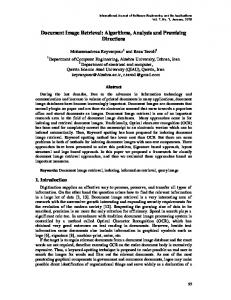
• Merge results. When the comparisons of all nodes end, the 15 best results of each one are sent to the neighbor node using the high speed interface. In the destination node the results are merged with its own results obtaining the 15 best results of those nodes. The result is sent again to the next node doing the same process. At the end the first node sends the 15 best results of the whole cluster to the host PC. In this case is not difficult to identify which parts of the algorithms are implemented in software and which ones are selected for the FPGA logic. The data delivery is done by the PowerPC processor that programs the DMA interface to sequentially dump the signatures database in the coprocessors input. The coprocessor then performs all the calculus, comparison and sorting. The DMA channel is able to deliver 64 bits per cycle, which represents 2 integers that can be processed in parallel. To get a significant acceleration using the SMILE cluster against a standard microprocessor based cluster is important to work on fixed point numbers on the FPGA. The original CBIR algorithm works with floating point numbers, but it was checked that using integer numbers with 32 bits precision the results are the same. After processing all the elements of the image database the data are sent back to the PowerPC processor that is in charge of the merge process. 5.2. Coprocessor Architecture. The coprocessor architecture to calculate the distance between the signatures and order the results is shown in figure 5. The developed hardware has five blocks: • PLB Custom Interface (PLBCI). This interface was created to allows the peripheral registers to be mapped in the PowerPC memory space, and a DMA controller memory transfer between the internal FIFOs and the main system memory. • Signature. This block is a 42 words length register, accessible via the PLBCI interface that stores the signature that is going to be compared with the data base. • Distance Calculus. A euclidean distance is calculated with two signatures, one to be compared and other that comes from the memory, it is subtracted word by word and the difference is accumulated. 11
Processor Local Bus
PowerPC Embedded Processor
CBIR Coprocessor
CBIR
PLBCI
Registers
Signature
DDR RAM
WrFIFO RdFIFO
Euclidean distance calculus
Ethernet MAC
DMA controller
Comparison and sorting
L(u, v) =
qP 2
n i=0 (ui
− vi )2
SysACE
Figure 5: Coprocessor Architecture.
• Comparison and sorting. This block compares the result from the distance calculation with the previous results. If the comparison result is one of the 15 best, it is loaded in the buffer in its corresponding position. It is important to notice that these tasks can be processed separately, so the whole process can be pipelined to increase the performance of the system processing two words per cycle. The coprocessor must be connected to the system bus to allow the PowerPC processor to send the data to be processed. The images signatures are sent to the coprocessor by DMA transfer. For that purpose the whole infrastructure required for DMA transfers in the SMILE nodes has been developed from scratch. This infrastructure includes the hardware side connected to the PowerPC system bus that manages the memory transfers, and the Linux driver that manages all the process from the operating system point of view. Using these mechanisms the CBIR application is able to access the DDR memory of the board in bursts, processing almost one 64 bit word per cycle to the coprocessor. The signatures are stored in a 128MB buffer in the DDR memory. To create a buffer of 128MB of contiguous memory physical memory in Linux we used a Kernel patch called bigphysarea that allow to reserve a amount of system memory before Linux kernel memory system starts. After deciding the partitioning and establishing the coprocessor architecture all the design was carried out following the SystemC design flow presented in section 4. At the end of the flow we obtain a SystemC synthesizable version of the coprocessor ready to interact with the PLBCI and the MPI application that will run on the PowerPC.
12
6. Architecture Evaluation 6.1. Experimental Setup With the objective of evaluating the SMILE architecture a set of tests has been performed with the parallelized CBIR implementation presented in section 5. In these tests the SMILE architecture is compared with a high performance cluster architecture, called CALDERON. This is an HP Cluster with up to 134 processors connected with Gigabit Ethernet. The cluster is made up of 1 Front-end HP Proliant DL 380 Third Generation bi-processor; 15-node HP Proliant DL 145 (first generation), with two 2.2 GHz AMD Opteron 248 processors and 4 GB of main memory; and 20 HP Proliant DL 145 (second generation) with four 1.8 GHz Dual Core AMD Opteron and 8 GB of main memory. Only 32 processors were used, that is 8 HP Proliant DL 145 2nd generation machines. For the experiments each processor are referred as a node in order to compare to each SMILE node. In order to prove the portability features, the parallelized implementation used in these tests is the same for both architectures. The only difference between the two cases is that the Verilog code of the SMILE version is replaced by software functions. Therefore the communication patterns and the communication functions are the same in both implementations. This implementation has been developed using C and LAM/MPI 7.1.1 library. The tests collect the response time measurements for the parallelized versions of the algorithm both in the HP cluster and the SMILE architecture. Two kind of tests have been developed, with different size and DB distributions. In all the experiments several results for different numbers of nodes and DB sizes have been measured. Table 6.1 shows the communication times for different packet sizes and different jumps in the routing process. The performance of the SCE-based network get worse when the size of the packet grows. Also the number of nodes that a packet has to cross, does not increase the communication time dramatically. 6.2. Experimental Results In the first experiment a constant number of signatures for each computational node was defined. Therefore, the size of the DB is different for each configuration, and will be calculated as the number of signatures per node multiplied by the number of nodes in the cluster. In this way, all the nodes must use the same amount of time performing for the computations, 13
HP Cluster 5 4.5 4
DB size: 199728 DB size: 399456 DB size: 798912 DB size: 1597828 DB size: 3195660
0.9
3.5
Time (s)
Time (s)
SMILE 1
DB Size: 199728 DB Size: 399456 DB size: 798912 DB size: 1597828 DB size: 3195660
3 2.5 2
0.8 0.7 0.6
1.5 1
0.5 0
5
10 15 20 25 Number of cluster nodes
30
35
0
(a) Cluster.
5
10 15 20 25 Number of cluster nodes
30
35
(b) SMILE architecture.
Figure 6: Response time of the first experiment.
Ethernet [ms] SMILE d=1 [ms] SMILE d=2 [ms] SMILE d=3 [ms] SMILE d=4 [ms]
Size of packet in bytes 256 512 1024 2048 2 2.1 2.3 2.6 0.4 0.5 0.7 1.4 0.4 0.6 1.1 2.1 0.45 0.61 1.2 2.3 0.5 0.62 1.3 2.4
Table 1: Communication time in SMILE for different packet size.
whatever the size of the cluster. Hence, the differences in the response times for each cluster size will be due to the communication overhead. Figures 6(a) and 6(b) show the statistics of several configurations increasing the DB size for the cluster and the SMILE architecture, respectively. In the second experiment, the total size of the DB is constant for all of the configurations. Hence for each system’s configuration, each of the nodes computes a number of signatures which can be calculated as the DB size divided by the number of nodes in this configuration. Therefore, the larger the configuration is, the smaller the response time should be. Figures 7(a) and 7(b) respectively, show the results obtained in traditional cluster and SMILE architecture. Analyzing the results presented in the previous figures, it is worth to highlight that the response times of architecture SMILE are better than the obtained with the cluster, for all the tests performed (for all the configurations and DB sizes). The achieved speedup is shown in 8, where it is possible to notice that the speedup of the SMILE architecture grows with the number of nodes in the configuration. However, with respect to the size of the DB,
14
Response time for different size of data base.
Response time for different size of data base.
5
4
Response time [s]
Response time [s]
4.5
3.5 3 2.5
4 nodes 8 nodes 16 nodes 32 nodes
2 1.5
2.4 2.2 2
4 nodes 8 nodes 16 nodes 32 nodes
1.8 1.6 1.4 1.2 1 0.8 0.6
1
0.4 0
5e+06
1e+07 1.5e+07 2e+07 2.5e+07 3e+07 Signatures in the database
0
(a) Cluster.
5e+06
1e+07 1.5e+07 2e+07 2.5e+07 3e+07 Signatures in the database
(b) SMILE architecture.
Figure 7: Response time of the second experiment.
the best speedups are those with the smaller sizes, although the variation is much less remarkable. The results presented in the first experiment (Figure 6) show an increase in response times in both architectures with respect to the number of nodes. This behavior is a consequence of the strong impact of the communication overload, which is far bigger that the computation time. However, as shown in figure 6, the increase in the SMILE architecture is smaller than in the HP cluster and with a smaller slope. This behavior is also shown in the speedup figures, and is the reason of the linear increase of the speedup with respect to the number of nodes. This implies that the SMILE architecture has better scalability features than the HP cluster in this application and for these communication patterns. In the second experiment the size of the DB is constant for all the configurations. Therefore, increasing the number of nodes, the response times should be smaller. This is what it happens in the SMILE architecture as can be observed in the figure 7. This increase in the performance is more remarkable for greater sizes of the DB. Nevertheless, in cluster the response times grows whatever the number of nodes. Again, the communication overload is greater than the advantage of using more nodes to do the calculation. In view of the above we can point out that the SMILE architecture offers better features (both in performance and scalability) that those of the cluster, for the CBIR application. With respect to the power consumption some measurements have been made in both architectures. As for the cluster, each of the nodes consumes
15
8 7
DB Size: 199728 DB Size: 399456 DB size: 798912 DB size: 1597828 DB size: 3195660
8 7 Speedup
6 Speedup
9
DB Size: 199728 DB Size: 399456 DB size: 798912 DB size: 1597828 DB size: 3195660
5 4 3
6 5 4 3
2
2
1
1 0
5
10
15 20 Number of Nodes
25
30
35
0
(a) First experiment.
5
10
15 20 Number of Nodes
25
30
35
(b) Second Experiment.
Figure 8: Speedup of the SMILE architecture vs. the cluster.
about 500 W of power. Each one of these nodes has four processors, thus to reach a 32-processor configuration, it is necessary to use only 8 nodes, with a total consumption of about 4,000 W. Additionally, the communications switch consumes 500 W. Therefore the total power consumption of the cluster is around 4,500 W. On the other hand, the measurements performed in the FPGA cards show that each of the cards consumes about 5,59 W and therefore the total power consumption of the SMILE architecture is around 179 W. In view of the above, it is possible to conclude that the power consumption of the SMILE architecture is a 3.9 % with respect to the cluster. 7. Conclusions and Future Work The last two decades have seen the emergence of Beowulf-class computers (clusters of commodity off-the-shelf hardware and Open Source software), which in combination with tremendous gains in single-chip processors, have had a profound effect on High-Performance Computing (HPC). Over half of the fastest 500 computers on the TOP500 list identify themselves as clusters. Even in an arena where speed is king, the marketplace still reflects a sensitivity to cost. On the other hand, despite the exponential growth of microprocessors, it is not clear that current technology will scale in the future. Issues beyond simply raw computational speed (such as power, cooling, and physical infrastructure) will become increasingly important. Just as important are other issues that arise from the performance of key subsystems, such as the bandwidth to primary storage, secondary storage, and networking. 16
For this reasons High Performance Computing should take advantage of all the technological and architectural opportunities that can improve the performance of the future supercomputers. In this paper SMILE, a new HPRC architecture based on a cluster of low-cost FPGAs boards is proposed. The cards are interconnected by a specific design ring network with Gigabit/s bandwidth. The most remarkable characteristics of this new architecture are the low cost, the low power consumption and the low area required for the cluster. It is also worth mentioning not only the high performance and scalability of the SMILE cluster for specific applications, but also the software portability for those parallel applications based on MPI, that can take advantage of the reconfigurable hardware. In this sense the architecture can execute MPI parallel applications, while taking advantage of the FPGA reconfigurability and performance. In order to test all the SMILE features, an MPI parallelized version of a Content-Based Information Retrieval (CBIR) application has been developed. The application has been designed following a two-step methodology: parallelization and Hardware-Software Co-design. In order to prove the portability, the same application has been run on the SMILE architecture and on a cluster, changing the Verilog code of the FPGA with software code. The most important conclusions that could be extracted from the experimental results presented in this paper are the following that the performance and scalability of the SMILE architecture is better than the performance and scalability of the HP cluster for the CBIR application. The speedups ranges from around 2 to 9, and grows with the number of processors. Future work in the subject includes more research in what are the best suitable applications for the SMILE architecture and cluster. Acknowledgments This work has been partially funded by the the Spanish Ministry of Education and Science (TIN2007-68023-C02-01 and Consolider CSD2007-00050), as well as by the HiPEAC European Network of Excellence. References [1] T. A. El-Ghazawi, E. El-Araby, M. Huang, K. Gaj, V. V. Kindratenko, D. A. Buell, The promise of high-performance reconfigurable computing, IEEE Computer 41 (2) (2008) 69–76. 17
[2] M. Gokhale, P. S., Reconfigurable Computing: Accelerating Computation with Field-Programmable Gate Arrays, Springer, Netherlands, 2005. [3] D. Buell, T. El-Ghazawi, K. Gaj, V. Kindratenko, Guest editors’ introduction: High-performance reconfigurable computing, Computer (2007) 23 – 27. [4] SGI, Rasc technology: Reconfigurable application specific computing, http://www.sgi.com/products/rasc/. [5] C. Inc, The supercomputing company: Cray xd1 supercomputer, http://www.cray.com/downloads/Cray XD1 Datasheet.pdf. [6] M. K, Cots supercomputing, 2007/20070710 cots.htm.
www.fpgajournal.com/articles
[7] R. Sass, W. Kritikos, A. Schmidt, Reconfigurable computing cluster (rcc) project: Investigating the feasibility of fpga, Custom Computing Machines (2007) 127 – 140. [8] E. Vonnahme, B. Griese, M. Porrmann, U. Rckert, Dynamic reconfiguration of real-time network interfaces, Parallel Computing in Electrical Engineering, International Conference on 0 (2004) 376–379. [9] K. D. Underwood, W. B. Ligon, R. R. Sass, W.b.: Analysis of a prototype intelligent network interface. concurrency and computing: Practice and experience (2002) 751–777. [10] V. Ross, Heterogeneous high performance computer, in: Proceedings of the 2005 Users Group Conference on 2005 Users Group Conference, 2005, p. 304. [11] C. Cathey, J. Bakos, D. Buell, A reconfigurable distributed computing fabric exploiting multilevel parallelism, Custom Computing Machines (2006) 121 – 130. [12] J. Wawrzynek, D. Patterson, M. Oskin, S. Lu, Ramp: Research accelerator for multiple processors, IEEE Micro (2007) 46 – 57. [13] O. Mencer, K. Tsoi, S. Craimer, T. Todman, Cube: A 512-fpga cluster, Southern Programmable Logic Conference. (2009) 51 – 57. 18
[14] T. Gneysu, T. Kasper, M. Novotn, C. Paar, Cryptanalysis with copacobana, IEEE Transactions on Computers (2008) 1498 – 1513. [15] I. S. Inc., Nallatech, www.nallatech.com/index.php/intel-xeon-fsb-fpgasocket-fillers.html. [16] I. Foster, Designing and Building Parallel Programs: Concepts and Tools for Parallel Software Engineering, Addison-Wesley Longman Publishing Co., Inc., Boston, MA, USA, 1995. [17] C. Pedraza, E. Castillo, J. Castillo, J. Bosque, J. Mart´ınez, J. Cano, P. Huerta, Content-based image recovering algorithm acceleration in a low-cost reconfigurable fpga cluster, in: IX Jornadas de Computaci´on Reconfigurable y Aplicaciones (JCRA), Alcal´a de Henares, Spain, 2009, pp. 517–528. [18] J. Bosque, O. Robles, L. Pastor, A. Rodr´ıguez, Parallel cbir implementations with load balancing algorithms, Journal of Parallel and Distributed Computing (2006) 1062 – 1075. [19] H.-W. Yoo, D.-S. Jang, S.-H. Jung, J.-H. Park, K.-S. Song, Visual information retrieval system via content-based approach, Pattern Recognition 35 (3) (2002) 749–769. [20] A. Rosenfeld (Ed.), Multiresolution Image Processing and Analysis, Vol. 12 of Springer Series in Information Sciences, Springer Verlag, 1984. [21] D. Marr, E. Hildreth, Theory of edge detection, in: Proceedings of the Royal Society, Vol. 207, London, 1980, pp. 187–217, ser. B. [22] I. Daubechies, Ten Lectures on Wavelets, Vol. 61 of CBMS-NSF Regional Conf. Series in Appl. Math., Society for Industrial and Applied Mathematics, Philadelphia, PA, 1992. [23] E. J. Stollnitz, T. D. DeRose, D. H. Salesin, Wavelets for computer graphics: A primer, part 1, IEEE Computer Graphics and Applications 15 (3) (1995) 76–84. [24] E. J. Stollnitz, T. D. DeRose, D. H. Salesin, Wavelets for computer graphics: A primer, part 2, IEEE Computer Graphics and Applications 15 (4) (1995) 75–85. 19
[25] A. Rodr´ıguez, O. D. Robles, L. Pastor, New features for Content-Based Image Retrieval using wavelets, in: F. Muge, R. C. Pinto, M. Piedade (Eds.), V Ibero-american Simposium on Pattern Recognition, SIARP 2000, Lisbon, Portugal, 2000, pp. 517–528, ISBN 972-97711-1-1.
20