www.nature.com/scientificreports
OPEN
received: 01 December 2015 accepted: 24 February 2016 Published: 10 March 2016
Continuous variable quantum optical simulation for time evolution of quantum harmonic oscillators Xiaowei Deng1,2, Shuhong Hao1,2, Hong Guo1,3, Changde Xie1,2 & Xiaolong Su1,2 Quantum simulation enables one to mimic the evolution of other quantum systems using a controllable quantum system. Quantum harmonic oscillator (QHO) is one of the most important model systems in quantum physics. To observe the transient dynamics of a QHO with high oscillation frequency directly is difficult. We experimentally simulate the transient behaviors of QHO in an open system during time evolution with an optical mode and a logical operation system of continuous variable quantum computation. The time evolution of an atomic ensemble in the collective spontaneous emission is analytically simulated by mapping the atomic ensemble onto a QHO. The measured fidelity, which is used for quantifying the quality of the simulation, is higher than its classical limit. The presented simulation scheme provides a new tool for studying the dynamic behaviors of QHO. The simulation for dynamic behaviors of a quantum system in general is difficult with any classical configurations. In 1982, R. Feynman envisaged a quantum simulator, which should be built of quantum mechanical elements, and thus it can naturally evolve according to quantum mechanics laws1. By using quantum simulation (QS), we can simulate the dynamic evolution of other quantum system with a controllable quantum system2–5. In recent years the study on QS has been growing rapidly since the development of quantum information science has prepared enough technologies to implement the manipulation of quantum systems and realize QS. Moreover, many potential applications of QS in variety of scientific fields are a strong motivation to push it progressing. Sizable theoretical proposals on QS have been proposed in the past decade5. In the experimental investigations the ultra-cold quantum gases6, trapped ions7,8, photonic system9,10, super-conducting circuits11, nuclear magnetic resonance (NMR)12–16, nitrogen-vacancy centers17, and so on, have been used as the controllable quantum systems to implement QS. Some experiments on simulating the dynamic processes in the condensed-matter, chemical, biological and frustrated systems have also been demonstrated5,18–20. In the achieved QS experiments, the used quantum variables are discrete variables (DV) with finite dimensions. Usually, high fidelity can be obtained in the DVQS system, such as trapped ions7, photonic10, and NMR13–15 systems. Although the continuous variable (CV) quantum information and quantum computation (QC) based on applying quadrature amplitude and phase of quantized optical mode (qu-mode) to be quantum variables have been extensively explored21–29, QS scheme utilizing qu-mode and logical operations in CVQC to mimic the dynamics of the other quantum systems has not been implemented before. Very recently, a QS scheme of quantum field theory using continuous variables is proposed30. In physics the dynamics of numerous systems is governed by the harmonic oscillator equations, thus the study for dynamic behaviors of harmonic oscillators has general significance. As an important model system in quantum mechanics, quantum harmonic oscillator (QHO) has been extensively investigated. However, it is difficult to observe the transient behaviors of the quantum state of a high frequency QHO in the time evolution directly. Untill now, only the truncated QHO was simulated with NMR system in DV regime12. As well-known qu-mode is a typical QHO, which can be applied to simulate the dynamics of some other QHO systems. For example, the direct experimental observation of the dynamics of an atomic ensemble in the collective spontaneous emission is difficult, but it can be simulated by the time evolution of a QHO31. 1
State Key Laboratory of Quantum Optics and Quantum Optics Devices, Institute of Opto-Electronics, Shanxi University, Taiyuan 030006, China. 2Collaborative Innovation Center of Extreme Optics, Shanxi University, Taiyuan 030006, China. 3College of Physical Science and Technology, Central China Normal University, Wuhan 430079, China. Correspondence and requests for materials should be addressed to X.S. ( email:
[email protected])
Scientific Reports | 6:22914 | DOI: 10.1038/srep22914
1
www.nature.com/scientificreports/ In this paper, we present the first CV quantum optical simulation (CVQOS) experiment, in which a qu-mode and a logical operation unit used in CVQC serve as the controllable quantum system to simulate the dynamic behavior of an other quantum system. At first, the transient behavior of a QHO in an open system is experimentally recorded and then the dynamics of an atomic ensemble in the collective spontaneous emission is analytically simulated by mapping an atomic ensemble onto a QHO as an example. The presented CVQOS enables one to simulate the time evolution of the quantum state in collective spontaneous emission of an atomic ensemble. Under the condition of satisfying the limitations imposed by the Holstein-Primakoff transformation (HPT)31, the time evolution of the uncertainty of the collective spin component, the spin-squeezing parameter and the population of atomic upper-state during the collective spontaneous emission are analytically mimicked by the CVQOS. The fidelity of the presented simulation is higher than the corresponding classical limit. If more qu-modes and logical operations are applied the presented scheme perhaps can be extended to simulate a multimode system, such as the evolution of coupled harmonics oscillators32,33.
Results
(
Time evolution of a quantum harmonic oscillator. The Hamiltonian of a QHO is Hˆ = ω aˆ †aˆ + †
1 2
),
in which ħ is the Plank constant, ω is the resonant frequency of the oscillator, aˆ and aˆ are the creation and annihilation operators, respectively. In an open system, the QHO will interact with the environment and under the † † rotating wave approximation the Hamiltonian is given by Hˆ O = ωaˆ †aˆ + ∑kωkbˆ k bˆ k + ∑kg k (bˆ k aˆ + bˆ k aˆ †), where the second and third terms represent the environment and the interaction between the QHO and environ† ment, respectively, gk is the interaction coefficient, bˆ k and bˆ k are the creation and annihilation operators of the k-th mode in the vacuum reservoir, respectively. According to the Hamiltonian of a QHO in an open system with vacuum environment, the time evolution of the dimensionless position and momentum operators Xˆ (t ) and Pˆ (t ) are expressed by −κt ˆ Xˆ (t ) ˆ = cos ωt sin ωt X (0)e + F X (t ) , Pˆ (t ) −sin ωt cos ωt Pˆ (0)e−κt Fˆ P (t ) (1) where Xˆ (t ) = (aˆ (t ) + aˆ (t )† )/2 and Pˆ (t ) = (aˆ (t ) − aˆ (t )† )/2i, κ is the decay rate, and Fˆ X (t ) and Fˆ P (t ) are the noise operators depending on the reservoir variables, which guarantees the time-invariant of the commutation relation between position and momentum operators34. For the vacuum reservoir we have Fˆ X (t ) R = Fˆ P (t ) R = 0, 2 2 〈Fˆ X (t ) 〉R = 〈Fˆ P (t ) 〉R = (1 − e−2κt )/4, and FˆX (t ) FˆP (t ) R + FˆX (t ) FˆP (t ) R = 0, where the subscript R represents the average of the reservoir. When κ = 0, there is no interaction between the QHO and the vacuum reservoir, which means that the QHO is in a closed system. When κ ≠ 0, Eq. (1) describes the case in an open system, where Xˆ (t ) and Pˆ (t ) will attenuate with time. From Eq. (1) we can see, if taking θ = ωt, the time evolution of a QHO can be simulated by a rotation operation of a qu-mode in phase space24. In this way, we can observe the real-time evolution of the quantum state of a high frequency QHO and record the transient process of the rapid evolution easily. A schematic for quantum simulation is shown in Fig. 1(a), The simulated system evolves from the initial state ˆ ϕ (0) to ϕ (t ) , where Uˆ = e−iH syst/ , and Hˆ sys is the Hamiltonian of the simulated system. The quantum simulator is a controllable system consisting of three parts: preparing the initial state ψ (0) (initialization), implementˆ ing the desired unitary evolution Uˆ ′ = e−iH simt/ (evolution), and measuring the final state ψ (t ) (measurement)5. If a mapping between the simulated system and the simulator [ ϕ (0) and ψ (0) , ϕ (t ) and ψ (t ) , Uˆ and Uˆ ′] exists, the system can be simulated by the quantum simulator. The experiment set-up is shown in Fig. 1(b). In the experiment, the qu-modes in a coherent and an amplitude-squeezed state with − 3.5 dB squeezing are used as input states to simulate the time evolution of other QHOs, respectively. The amplitude of the coherent (squeezed) state is α =1.58, which is obtained by applying a 10 dB amplitude modulation at 2 MHz on the input state by means of an electro-optical modulator (EOM3). The rotation operation is implemented by means of an ancillary Einstein-Podolsky-Rosen (EPR) entangled state with −3.5 dB squeezing (i.e. the squeezing parameter re = 0.40), which is generated from a non-degenerate optical parametric amplifier (NOPA)35–37. A continuous wave intracavity frequency-doubled and frequency-stabilized Nd:YAP/LBO (Nd-doped YAlO3 perorskite/lithium triborate) laser is used to pump the NOPA. The NOPA consists of an α-cut type-II KTP crystal and a concave mirror. The front face of the KTP was coated to be used for the input coupler and the concave mirror serves as the output coupler of the entangled state. The transmittance of the input coupler at 540 nm and 1080 nm are 99.8% and 0.04%, respectively. The transmittance of the output coupler at 540 nm and 1080 nm are 0.5% and 5.2%, respectively. The NOPA is operated at de-amplification condition, which corresponds to lock the relative phase between the pump laser and the injected signal to (2n + 1)π (n is the integer). In this way, the EPR entangled state with anti-correlated amplitude and correlated phase quadratures is generated. Another NOPA is used to generate the amplitude-squeezed state, which is also used as an input state. When the NOPA is operated at de-amplification condition, the coupled-modes of two EPR entangled beams at +45° and −45° polarization directions are the quadrature-amplitude and the quadrature-phase squeezed states, respectively38. The measured squeezing and anti-squeezing noises of the quadrature-amplitude squeezed state are −3.5 dB and 8.5 dB, respectively. The quantum efficiency of the photodiode (FD500W-1064, Fermionics) used in the homodyne detection system is 95%. The interference efficiency on a beam-splitter is about 99%. The fluctuation of the phase locking system is about 2–3°.
Scientific Reports | 6:22914 | DOI: 10.1038/srep22914
2
www.nature.com/scientificreports/
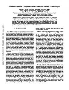
Figure 1. Schematic and experimental set-up of the quantum simulation system. (a) The simulated quantum system evolves with the unitary of Uˆ , the quantum simulator consisting of three parts: initialization, simulated evolution with the unitary of Uˆ ′ and measurement. (b) The experimental set-up. The part of initialization is for the preparation of input state. In the simulated evolution, the input state after the interaction with the environment and a submode of the EPR entangled state are coupled on a 50% beam-splitter, and then the output beams are measured by the homodyne detection systems (HD1 and HD2) with measurement angles θ1 and θ2, respectively. The measurement results of them are combined together in the feedforward circuit, and are fedforward to the other submode of the EPR entangled state through EOM1, EOM2 and a 99% reflection beamsplitter. Finally, in the part of measurement, the output state is measured by the third homodyne detection system HD3.
In the experiment, a CV teleportation based scheme is used to implement the rotation operation of a qu-mode. An input mode is coupled to a submode of the EPR entangled state via a 50% beam-splitter. The two output modes of the beam-splitter are measured by two homodyne detection systems HD1 and HD2 with measurement angles θ1 and θ2, respectively. The measured results are combined together in the feedforward circuit and then are fedforward to the other submode of the EPR entangled state by EOM1, EOM2 and a 99% reflection beam-splitter. The specific features of such a rotation operation scheme are: 1. the output quantum state is not destroyed and its quantum features can be retained. 2. Since, in fact, the rotation operation based on CV teleportation is a logical gate in CV quantum computation21–29 and thus it can be integrated in a gate sequence to simulate a complex quantum dynamics. In the teleportation based rotation operation scheme, the measurement angles θ1 and θ2 in HD1 and HD2 are controlled to simulate the evolution of the input state. The measurement results of HD1 and HD2 are Xˆ d1 = cos θ1(Xˆ 1 − Xˆ in )/ 2 + sin θ1(Pˆ 1 − Pˆ in)/ 2 and Xˆ d2 = cos θ2(Xˆ 1 + Xˆ in)/ 2 + sin θ2(Pˆ1 + Pˆin)/ 2 , where Xˆ 1 (Pˆ 1) and Xˆ in (Pˆ in) are the amplitude (phase) quadrature of one EPR entangled mode and input mode, respectively. The output state of a qu-mode in a closed system is expressed by Xˆ Xˆ ˆ ˆ ˆ out = 2 + G X d1 = M X in + δ1 , ˆ ˆ ˆ ˆ ˆ Pout P2 X d2 Pin −δ 2
(2)
where Xˆ 2 and Pˆ 2 are amplitude and phase quadratures of the other EPR entangled mode, and − 2 sin θ2 g1 g 2 sin θ− G = g g = 3 4 2 cos θ2 − sin θ−
Scientific Reports | 6:22914 | DOI: 10.1038/srep22914
2 sin θ1 sin θ− 2 cos θ1 sin θ−
(3)
3
www.nature.com/scientificreports/ is the gain factor in the feedforward loop, in which θ + = θ 1 + θ 2 and θ − = θ 1 − θ 2 , respectively. δˆ1 = Xˆ 1 + Xˆ 2 = 2 e−r e Xˆ v and δˆ 2 = Pˆ 1 − Pˆ 2 = 2 e−r e Pˆ v are the excess noise of the EPR state, where Xˆ v and Pˆ v represent the amplitude and phase quadratures of a vacuum state. Obviously, in the ideal case with infinite squeezing (r e → ∞), these excess noises will vanish, and the better the squeezing is, the smaller the noise terms are. When θ1 = θ2 + 3π/2, θ2 = θ /2, the transformation matrix sin θ+ cos θ− − cos θ+ sin θ− sin θ− M= sin θ+ cos θ− + cos θ+ sin θ− sin θ−
(4)
becomes the rotation transformation matrix cos θ sin θ , and the dynamic behavior of the QHO at ωt = θ will −sin θ cos θ be exhibited. In the experiment process, we calculate the gain factor and transformation matrixes G and M according to equations (3) and (4) for a certain rotation angle θ at first. Then, the measured results Xˆ d1 and Xˆ d2 of HD1 and HD2 are combined together according to g 1Xˆ d1 + g 2 Xˆ d2 and g 3Xˆ d1 + g 4 Xˆ d2 in the feedforward circuit, and are fedforward to the amplitude and phase quadratures of the other submode of the EPR entangled state, respectively. The output state is measured by the third homodyne detection system HD3. In HD3, the relative phase between the local oscillator and the output optical beam is scanned with a frequency of 2 Hz, which enables one to perform quantum tomography39,40. The AC output signal from HD3 is mixed with a local reference signal of 2 MHz, then it is filtered by a low-pass filter with a bandwidth of 10 kHz and amplified 1000 times (Low noise amplifier, SRS, SR560). Finally, it is recorded by a digital storage oscilloscope. The DC output from HD3 is used as a trigger signal to record the output results. The sampling rate is chosen to be 500 kpts/s. About 50000 data points are used to reconstruct the Wigner function of the output state. Generally, the interaction between the input state and vacuum environment results in the linear attenuation of the amplitude of the qu-mode can be mimicked by an adjustable beam-splitter composed by a half wave plate (HWP) and a polarization beam-splitter (PBS). The rate of the attenuation is proportional to the strength of the interaction and the change of the interaction coefficient is mimicked by adjusting the transmittance of the beam-splitter. For an open system with the vacuum environment, the output state becomes ˆ ˆ X out = cos θ sin θ T X in + ˆ −sin θ cos θ ˆ Pout Pin
Xˆ δˆ 1 − T v + 1 . Pˆ v −δˆ 2
(5)
Comparing Eq. (5) with Eq. (1), we can see that the de-coherence of the input state induced by the environment is exactly simulated by the beam-splitter with T = e−κt .
Experimental results. When T