Control of Articulated Snake Robot under Dynamic. Active Constraints. Ka-Wai Kwok, Valentina Vitiello, and Guang-Zhong Yang. The Hamlyn Centre for Robotic ...
Control of Articulated Snake Robot under Dynamic Active Constraints Ka-Wai Kwok, Valentina Vitiello, and Guang-Zhong Yang The Hamlyn Centre for Robotic Surgery Imperial College London, London, United Kingdom {k.kwok07,v.vitiello07,g.z.yang}@imperial.ac.uk
Abstract. Flexible, ergonomically enhanced surgical robots have important applications to transluminal endoscopic surgery, for which path-following and dynamic shape conformance are essential. In this paper, kinematic control of a snake robot for motion stabilisation under dynamic active constraints is addressed. The main objective is to enable the robot to track the visual target accurately and steadily on deforming tissue whilst conforming to pre-defined anatomical constraints. The motion tracking can also be augmented with manual control. By taking into account the physical limits in terms of maximum frequency response of the system (manifested as a delay between the input of the manipulator and the movement of the end-effector), we show the importance of visual-motor synchronisation for performing accurate smooth pursuit movements. Detailed user experiments are performed to demonstrate the practical value of the proposed control mechanism.
1 Introduction Recent technological advances in surgery are driven by early intervention, consistent surgical outcome and accelerated patient recovery. This requires surgical procedures with improved quality, accuracy and minimally invasive access, made possible by preoperative and intra-operative imaging combined with flexible, ergonomically enhanced surgical robots [1]. Technically, the development of snake robot is motivated by the recent investigation of natural orifice or single port transluminal endoscopic surgery [2], for which path-following and dynamic shape conformance are important. Procedures that are clinically relevant to such devices include, for example, drug delivery systems for embryonic stem cell transplant into scarred myocardium, minimally invasive bilateral pulmonary vein isolation, and transmural epicardial ablation. The increased flexibility of these hyper-redundant robots also imposes significant challenges on kinematic control. For surgical navigation, the relative pose of the camera at the instrument tip during articulated movement is also important to consider ensuring stable vision and the avoidance of disorientation. Further challenges include the singularity problem while solving the inverse kinematics as the resultant inverse kinematic solutions may exceed the allowable workspace or the physical constraints of the robot actuation. For in vivo applications, the internal organs are in constant motion, so how to ensure path-following whilst maintaining dynamic shape conformance is a significant technical challenge. T. Jiang et al. (Eds.): MICCAI 2010, Part III, LNCS 6363, pp. 229–236, 2010. © Springer-Verlag Berlin Heidelberg 2010
230
K.-W. Kwok, V. Vitiello, and G.-Z. Yang
Previous work [3] has introduced a modelling scheme of dynamic active constraints with a volumetric pathway. It is able to adapt to tissue deformation, thus providing an explicit safety manipulation margin for the entire articulated device, rather than only the tip of the robot. Such a constraint is also used in this study, which has two main purposes. First, we will introduce a control scheme for stabilising the camera reference frame at the end-effector relative to the deforming tissue so that the relative pose and distance of the camera to the tissue are maintained. The search for the optimal joint configuration of the robot is formalised as a minimization problem, in which the measures of the visual stability and the conformation to the allowable spatial constraint are introduced into the objective function. Secondly, the dynamic frequency response due to physical actuation limit is also considered. We hypothesise that for manipulation of such a robot when performing smooth pursuit movement, it is important to match the kinematic response of the manipulator controlled by the operator to that of the end-effector to ensure natural, stable user interaction. Detailed quantitative performance and usability assessment was carried out on a group of subjects using the proposed control scheme in a virtual environment with fully controllable joint parameters to demonstrate the practical value of the method.
2 Methods 2.1 Kinematics of Articulated Robot under Dynamic Active Constraints In this paper, the robot model consists of a series of rigid links connected by universal joints. Each universal joint is operated by two actuators providing two rotational DoFs along perpendicular axes. For the prescription of active constraints, it is assumed that the anatomical pathway is pre-defined through the use of pre- and intra-operative data. The spatial constraint follows the tissue surface and dynamically adapts to tissue deformation in real-time. A 4×4 matrix i −1iT (α , β ) describing the homogenous transformation between the frame of link i and the frame of link i-1 can be expressed in terms of two angular values α and β of the universal joint actuating link i. The transformation between the world coordinate system W and the link l (with L links in total) is expressed in Eq. (1), where w0T is a constant matrix describing the pose of the first link with respect to the world reference frame.
⎧ l ⎫ T ( q l ) = w0T ⎨∏ i −1iT ( q2i −1 , q2i ) ⎬ : l = 1,..., L ⎩ i =1 ⎭
w l
(1)
The vector ql = [ q1 ,..., q2l ] represents the values of the joint angles affecting the pose of the link l. The pose of the end-effector on the distal link (i.e. the camera) is therefore determined by the set of angular joint values q = [ q1 ,..., q2 L ] .
2.2 Optimal Robot Configuration for Visual Stabilization For visual stabilisation and optimal joint control, the objective function used measures how well the joint configuration q tracks and visualizes a moving target. This includes the following two sub-objective functions.
Control of Articulated Snake Robot under Dynamic Active Constraints
231
Sub-objective 1: To minimize the collision depth to the constraint pathway enclosing the robot, i.e., L
{
}
ObjV1 ( q ) = w1 ∑ exp ( ki ⋅ pi ( q ) ) − 1 : 0 < ki ≤ ki −1 i =1
(2)
To simplify proximity queries, articulated devices are usually modelled as a series of primitives such as cylinders and spheres to represent the links and rotational joints [4]. However, to compute the deviation outside of the constraint, the robot is represented by a set of surface vertices. Assuming the vertex coordinates of link l are T x lj =1...V , x = ( x, y, z ,1) , the deviation of the robot link l due to joint configuration q is calculated as:
{
}
pl ( q ) = max I ( wlT ( q ) xlj =1...V ) j
(3)
where I ( x ) in Eq. (3) is an implicit function of a 3D Cartesian point and its iso-value is the shortest Euclidean distance from the input coordinate to the constraint surface ∂Ωt varying with time t, where Ωt denotes the forbidden region outside of the constraint zone. If a point is within the pathway, the output value is zero, as defined in Eq. (4). ⎧⎪ min x − x∂Ω : x∂Ω ∈ ∂Ωt if x ∈ Ωt t t (4) I ( x) = ⎨ otherwise ⎪⎩0 The objective function in Eq. (2) weighted by w1 is devised as a sum of exponential functions mapped from the deviations caused by each robot link. The exponential constants ki ≤ ki −1 are set so that the constraint is reinforced on proximal links closer to the base of the robot. This ensures that the major portion of the robot adapts to the deformation without deviating outside of the pathway during the motion tracking. Sub-objective 2: To maintain an optimal viewing angle at a given distance to the target, i.e., ∧ w ObjV2 ( q ) = 2 cos −1 −d tar ⋅ ntar (5)
{
π
}
The joint configuration is updated frame-by-frame so as to keep steady visualization of the moving target by compensating for motion disparity. Large motion disparity relative to the camera coordinate frame causes residual images which often adversely affect the surgical performance. It can be reduced by aligning the relative coordinate frame along the tissue surface normal. We assume that the motion of the visual target xtar ( t ) and its surface normal ntar ( t ) are estimated accurately by online tissue tracking (e.g. [5]). By aligning the camera coordinate frame to the robot end-effector, we can express the vector d tar pointing from the camera to the target, and the camera viewing direction d cam as follows: dtar = xtar − wLT ( q ) [ 0, 0,0,1] , T
d cam = Lw R ( q ) [ 0, 0,1,1]
T
(6)
where R ( q ) is also a homogenous matrix given by the rotation elements of T ( q ) . To eliminate viewing disparity between time frames, the problem can be reformulated so as to satisfy the following non-linear constraints: 2 d diff = ( d tar − d c ) ≤ Δd 2 and θv = cos −1 dˆ tar ⋅ d cam ≤ Δθ (7) w L
w L
{
}
232
K.-W. Kwok, V. Vitiello, and G.-Z. Yang
where d c is the optimal distance, Δd and Δθ are respectively the tolerances of the viewing distance and angle to the target and the caret ^ indicates the vector is in unit length. By constraining the target movement on the image plane, we devise the cost function as in Eq. (5) such that the search converges to the configuration in which the visual direction is in parallel to the surface normal n tar of the target. 2.3 Joint Space Motion Planning
To avoid local minima and enable the solution to converge towards an optimum, the initial configuration q 0 of joint space motion is determined based on the profile of the constraint pathway. We assume that the target moves periodically, s.t. xtar ( t ) = xtar ( t + T ) , and there exists a time moment t0 at which the target is temporarilyG at rest s.t. x′tar ( t0 ) = 0 . Having set the robot initially in a straight configuration q = 0 with the camera pointing at target xtar ( t0 ) at distance d c , each joint value T q 0 = ⎡⎣ q10 ,..., q20L ⎤⎦ is then computed in descending order from joint L to 1 by imposing the condition of minimal deviation outside of the constraint. The solution q 0 is within a physically allowed range of angular displacements [q lb , q ub ] . In addition to the optimization constraints introduced in Eq. (7), the physical limit of robotic actuation is also addressed by bounding the joint velocities [q� lb , q� ub ] according to the maximum motor speed and acceleration. Assuming a very short time interval Δt between frames, the velocity limit can be converted to an angular displacement range referring to the q i −1 optimised at the previous frame i-1. Thus, the overall constraint is expressed as: ⎧⎪q lb ≤ qi ≤ q ub (8) ⎨ i −1 i i −1 ⎪⎩( Δt ⋅ q� lb + q ) ≤ q ≤ ( Δt ⋅ q� ub + q )
Once the optimal configuration of q ( t ) is obtained frame-by-frame and interpolated to obtain a periodic robot motion, the motion is validated for implementation under the physical torque allowance τ max of each joint. Given the motion in terms of �� ( t ) ⎦⎤ and the mass of each link, the required dynamic torque can be ⎣⎡q ( t ) , q� ( t ) , q computed over the entire motion by using an iterative Newton-Euler dynamics algorithm [6]. In case of unfeasible motion, the corresponding configurations are reoptimised under a stricter velocity constraint [q� ′lb , q� ′ub ] . The valid motion q� ( t ) is then generated by combining all the feasible optimal configurations.
2.4 Human-Robot Interaction To facilitate area, rather than single feature exploration, manual control is provided for manipulating the robot while dynamically tracking the tissue motion. Having computed the robot tracking motion for points surrounding the target, each motion can be parameterised by Hermite interpolation using only two parameters ( u , v ) . The parameterised motion function becomes Q ( u, v, t ) , s.t. Q ( 0, 0, t ) = 1 q� ( t ) , Q (1, 0, t ) = 2 q� ( t ) , Q ( 0,1, t ) = 3 q� ( t ) and Q (1,1, t ) = 4 q� ( t ) by assuming a four-point neighbourhood, where u, v ∈ [ 0,1] and i q� ( t ) : i = 1...4 are the optimised motions generated by tracking the neighbouring targets. After parameterization, the resultant joint
Control of Articulated Snake Robot under Dynamic Active Constraints
233
� velocity q� not only depends on the tracking motion itself, but also on the varying rate of the two parameters, ( u� , v� )
∂Q ( u , v, t ) ∂Q ( u, v, t ) ∂Q ( u , v, t ) � : q� uv ( u� , v�, t ) = (9) q� = q� uv ( u� , v�, t ) + u� + v� ∂t ∂u ∂v 2-DoF operator control is obtained by manual variation of the parameters using a haptic device for exploring the surrounding region of the target. In this case, it is necessary to provide a damping force to hinder the excessive robot dynamics generated by manual control. A threshold Δq� is set to limit the joint velocities q� uv ( u� , v�, t ) due to the manual control and added on the existing tracking motion. This can be considered as a safety margin for defining the damping coefficient as: c (10) : b ( u� , v�, t ) = min Δq� − q�i ( u� , v�, t ) , i = 1...2 L fb = i b ( u� , v�, t )
{
}
where b is the minimal difference between Δq� and q�i among all the joints. When one of the joint velocities is reaching the safety margin, stronger force is applied to stop the hand motion before b → 0 . Because of the physical limitations of the haptic device an elastic force is implemented instead, but the avoidance of excessive robot dynamics is still ensured.
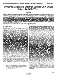
3 Experiments and Results The proposed tracking method is generic for snake type robots. To evaluate its performance under realistic conditions, epicardial ablation for modified MAZE procedure is considered. The target motion with sequence of 50 frames is first extracted from a 4D model reconstructed by the CT data. The target motion relative to the static camera coordinate frame is depicted in Fig. 1(a), which is highly correlated to the cardiac motion at 1Hz and the peak-to-peak displacement is about 6.1mm. The simulated 5-link (L=5) articulated robot features 10 rotational DoFs limited by ⎡⎣ qi ,lb , qi ,ub ⎤⎦ = [−40°, 40°] , ⎡⎣ q�i ,lb , q�i ,ub ⎤⎦ = [ −25°, 25°] s −1 with i = 1,..., 2 L and τ max = 16.6 mNm. The mass, radius and length of each link are 33g, 6mm and 20mm, respectively. Manipulating the robot not exceeding the dynamic active constraints is always considered a higher priority during the minimization, s.t. w1 > w2 . The processing time required mainly depends on the deviation distance calculation in Eq. (2). The computational complexity is approximately proportional to the number of vertices in the model. The minimization was performed off-line and preoperatively (we used MatLab on a PC with Intel Core2 Duo CPU T7100 and 2GB RAM). The time for proximity queries on 767 vertices of a 5-link robot is below 15ms. The robot motion aiming to track the moving target is planned smoothly without exceeding the actuation limits, and the quantitative performances of the visual stabilization are shown in Fig. 1(b-e). Compared to the stationary robot without tracking enabled, the viewing angle relative to the target surface normal is slightly reduced to ensure a perpendicular view of the surface (Fig. 1(b)). However, the parameters characterizing the stability of the visual target along the camera are the viewing distance dtar and angular accuracy θ v (Eq. (7)) as shown in Fig. 1(c-d).
234
K.-W. Kwok, V. Vitiello, and G.-Z. Yang
(b)
Target movement X Y Z
5
0
-5
0.2
0.4
(c)
0.6
0.8
without tracking with tracking
30
1
0
0.2
0.4
0.6
0.8
1
Time (s)
(d)
Viewing distance
9.5
Viewing angle relative to the camera normal
40
without tracking with tracking
9
Angle (degree)
Distance (mm)
32
28 0
Time (s) ( )
8.5
8
Viewing angle relative to the target normal
34
10
Angle (degree)
Displacement (mm)
(a)
0
0.2
0.4
0.6
0.8
20 10 0
1
Time (s)
(e)
without tracking with tracking
30
0
0.2
0.4
0.6
0.8
1
Time (s)
(f)
Angular distance travelled by the joints
Angle (degree)
30 20 10
0
0
1
2
3
4
5
6
7
8
9
10
Joint index (1-10)
Fig. 1. (a) 3D time-varying position of the visual target; (b) viewing angle between camera direction and target surface normal; (c) viewing distance between the camera and the target; (d) angle reflecting how accurately the camera is pointing at the target during motion tracking; (e) angular travelled distance of each joint; (f) robot configurations aiming at different neighbouring targets
Compared to existing methods (e.g. [7]), the proposed approach eliminates the need of expressing the inverse kinematics of the end-effector in a closed-form, ensuring that a solution is always obtainable without having to deal with the presence of reduced-rank Jacobian singularities. Our method aims to determine an optimal configuration (i.e. minimum deviation from constraint and stable visualization) among a wide range of feasible solutions without having to specify the pose of the end-effector. As shown in the results, the camera can be stabilised at a predefined distance to the target d c = 8.2 mm. Also, the angular deviation can be highly reduced below 8°, ensuring accurate target visualization at the centre of the image by compensating any rapid movement. The improved stability is attributed to the satisfaction of the nonlinear constraints in Eq. (7). The advantage of using an articulated robot with high kinematic redundancy is to provide adequate flexibility to satisfy the strict criteria in the complex nonlinear constraints (i.e. Δd = 0.1 mm and Δθ = 8° ) under the actuation limits. Greater tolerances might be needed in case of low angular resolution of the joint actuator. Fig. 1(e) shows the angular travelled distance of the joints, demonstrating the movement burden is shared between joints. This ensures the tracking capability can be resumed by re-planning the joint motion in case of limited performance, such as motion
Control of Articulated Snake Robot under Dynamic Active Constraints
235
lock of a particular joint due to malfunction. In addition, singularities due to solutions with large joint angle differences between two consecutive timeframes are also avoided. Once the joint motion is planned for tracking the neighbouring targets (Fig. 1(f)), visual exploration of the surrounding region can be performed by the operator. Curved reference paths and spherical target objects conforming to the deformation are pre-defined on the tissue surface within the region. With the virtual camera mounted on the simulated end-effector, the operator can see those objects being stabilised visually within the central part of the screen. The performance of the visual exploration can be recorded during the task. Table 1. Measured performance indices averaged across the ten subjects studied
Complet. Time (Sec)
Feature targeting W/O haptic With haptic Mean SD Mean SD 135.3 15.9 133.6 14.9
Dis. Travelled (mm)
937.4
92.0
925.2
72.1
1.3
668.8
462.0
416.3
91.1
37.8
Deviation (deg)
12.8
2.9
10.4
1.7
18.3
9.7
6.1
5.8
1.0
40.4
Imp% 1.3
Path following W/O haptic With haptic Mean SD Mean SD 110.1 78.5 65.6 15.5
Imp% 40.4
Ten subjects were recruited to assess the performance of the method, for which haptic feedback is provided to limit the hand manipulation so that its movement is insync with the frequency response of the end-effector. Subjects were asked to operate the haptic device (Omni Phantom, SensAble Tech. Inc., USA) for targeting multiple spherical targets in sequence or on a curved path. This allows for a comparison of the performance for either individual feature targeting or smooth pursuit for path following. Each task was performed twice, with and without the haptic force for maintaining the manual control within the safety velocity margin. The task order was randomized to minimize the effect of learning. Subjects were allowed to familiarise with the control interface before performing the tasks. Note that all the tests were held under motion tracking and stabilisation. When target tracking is disabled, the operator can fully utilise the actuation and have fast-response control in varying ( u , v ) . However, not only the deformation is rapid, but also the variation of ( u , v ) is not designed for tissue tracking. Consequently, the operator is not able to track the target objects. A conservative velocity limit Δq� = 4.5°s -1 was set to constrain q� uv (Eq. (9)) for preventing the joints from exceeding their angular velocity limits while performing tissue tracking. Without haptic feedback, the subject introduces fast and wide movements, but a severe delay is imposed depending on the physical limit of the end-effector. Such a delay is common (and important to consider) in human-robot interaction especially when the user pushes the robot to its performance limit. The performance indices recorded in this study include task completion time, the total displacement of the robot end-effector and the path/target deviation, computed as the average of the total angular deviation between the camera viewing direction of the target or path and the optimal angle θ v deduced from Eq. (7). The mean and standard deviation of these indices measured with and without the use of haptic force for the tasks of feature targeting and path following are summarized in Table 1. The results clearly show a significant
236
K.-W. Kwok, V. Vitiello, and G.-Z. Yang
improvement in performing the path following task when visual-motor perception is synchronized. This implies that smooth pursuit movement requires matching of the kinematic response of the robot end-effector to the manipulation input of the operator.
4 Discussion and Conclusions In this paper, we have proposed a control method to stabilise the visualisation of a deforming tissue using an articulated robotic device. Results have shown that visual stabilisation is particularly important when using a flexible redundant robot since the pose of the camera at the distal tip is affected by the joint configuration. To avoid disorientation, it is necessary to ensure that the area of interest is always within the field-of-view of the camera and at a stable relative viewing angle. Residual motion of the image due to tissue deformation can be minimised by aligning the direction of camera along the surface normal. The experimental results of the proposed method demonstrate the capability of a redundantly articulated robot for compensating dynamic tissue deformation. Further investigation of the proposed method is also conducted when integrating manual control with haptic interaction. In this case, the dynamic frequency response of the robot is affected by physical actuation limits. Such a delay causes a mismatching between the visual feedback and the motion input of the operator and we have shown that for pursuit movement it can significantly influence the task performance. A damping haptic force is therefore used to matching the frequency response of the user-controlled manipulator with that of end-effector. Such knowledge should be of importance to the actual deployment of snake robots for robotic-assisted transluminal endoscopic procedures.
References 1. Taylor, R.H., Stoianovici, D.: Medical robotics in computer-integrated surgery. IEEE Transactions on Robotics and Automation 19, 765–781 (2003) 2. Swanstrom, L.L., Whiteford, M., Khajanchee, Y.: Developing essential tools to enable trans-gastric surgery. Surg. Endosc. 22, 600–604 (2008) 3. Kwok, K.W., Mylonas, G.P., Sun, L.W., Lerotic, M., Clark, J., Athanasiou, T., Darzi, A., Yang, G.Z.: Dynamic Active Constraints for Hyper-Redundant Flexible Robot. In: Yang, G.-Z., Hawkes, D., Rueckert, D., Noble, A., Taylor, C. (eds.) MICCAI 2009. LNCS, vol. 5761, pp. 410–417. Springer, Heidelberg (2009) 4. Li, M., Ishii, M., Taylor, R.H.: Spatial motion constraints using virtual fixtures generated by anatomy. IEEE Trans. Robotics 23, 4–19 (2007) 5. Mountney, P., Yang, G.Z.: Soft Tissue Tracking for Minimally Invasive Surgery: Learning Local Deformation Online. In: Metaxas, D., Axel, L., Fichtinger, G., Székely, G. (eds.) MICCAI 2008, Part II. LNCS, vol. 5242, pp. 364–372. Springer, Heidelberg (2008) 6. Luca, A.D., Ferrajoli, L.: A Modified Newton-Euler Method for Dynamic Computations in Robot Fault Detection and Control. In: IEEE International Conference on Robotics and Automation, pp. 3359–3364 (2009) 7. Fahimi, F., Ashrafiuon, H., Nataraj, C.: An Improved Inverse Kinematic and Velocity Solution for Spatial Hyper-Redundant Robots. IEEE Trans. on Robotics and Automation 18, 103–107 (2002)