Control of Double-Output Induction Machine for Variable Speed Wind Energy Conversion System Using Dynamic Vector Approach B.Chitti Babu, K.B.Mohanty
C.Poongothai
Department of Electrical Engineering, National Institute of Technology, Rourkela, Orissa (India)-769008.
[email protected],
[email protected]
Research Scholar, Indian Institute of Technology Madras, Chennai (India)-600036.
[email protected]
Abstract-In this paper modeling and control of doubleoutput induction machine for wind energy conversion system is investigated. An attempt to develop a vectorized dynamic model of induction machine which can be simulated as both motoring and generating mode when testing control strategies. Through the model developed in this paper can be used for simulating all types of induction generator configurations. The choice of synchronous rotating reference frame makes it particularly favorable for the simulation of double-output configuration in transient conditions. A Complete simulation model is developed for the control of the active and reactive power of the doubleoutput induction generator during wind variations.
I. INTRODUCTION With increasing attention on renewable energy resources, wind energy conversion Systems (WECS) are today’s one of the most popular subject that the researches are intensively carried on. Due to the highly variable wind velocity, variable speed constant frequency wind generating system has distinct advantages than the traditional constant speed constant frequency wind generating system such as more effective power capture, lower mechanical stress and less power fluctuation [1]. During last decades, an increasing interest has emerged on wind energy technology and it is considered to be one of the most important renewable energy resources. Today, it is one of the rapidly growing technologies and markets [2]. By the end of 2010[WWEA] the total installed capacity of wind energy is estimated to be more than 160 GW all around the world. During last ten years, the high penetration of wind turbines in the power system has been closely related to the advancement of the wind turbine technology and the way of how to control. Double-output induction machines are receiving increasing attention for wind energy conversion system during such situation because the main advantage of such machines is that, if the rotor current is governed applying field orientation
control-carried out using commercial double sided PWM inverters, decoupled control of stator side active and reactive power results and the power processed by the power converter is only a small fraction of the total system power. So Doubly-fed wound rotor induction machine with vector control is very attractive to the high performance variable speed drive and generating applications [3]. In this paper, an attempt to develop a vectorized dynamic model of induction machine which can be simulated as both motoring and generating mode when testing control strategies. Through the model developed in this paper can be used for simulating all types of induction generator configurations. The choice of synchronous rotating reference frame makes it particularly favorable for the simulation of double-output configuration in transient conditions. The induction machine is modeled in vectorized form in the synchronous frame. The d-axis is aligned with the stator space voltage vector. The injected rotor voltages (at slip frequency) are derived from PI controllers that regulate the active and reactive powers delivered by the generator. The speed is adjusted by the turbine pitch control to maximize the power generated at a given wind speed. The machine representations are based on the motor convention; consequently in the generator mode of operation, such quantities as stator active power (Ps), reactive power (Qs), wind turbine torque(Tw), electro magnetic torque (Te) are negative (with wm>0) while stator power (Pr) is positive for sub synchronous operation and negative for over synchronous mode.
II. SYSTEM CONFIGURATION There are two basic options of wind power conversion fixed speed and variable speed operation. In fixed operation, the aero turbine can be operated at a constant speed by blade-pitch control of the wind turbine even under varying wind speeds. This option was very
Authorized licensed use limited to: NATIONAL INSTITUTE OF TECHNOLOGY ROURKELA. Downloaded on April 21, 2009 at 00:06 from IEEE Xplore. Restrictions apply.
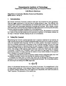
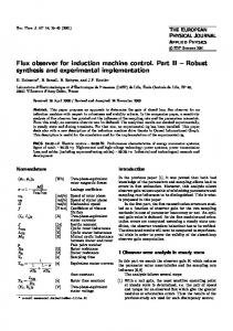
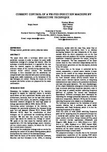
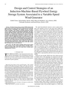
common because of the cost involved with the power converter needed in the variable speed generation to convert the variable frequency to match the constant grid frequency. In variable speed operation, the aero turbine rotational speed can be allowed to vary with wind to maintain a constant and optimum tip speed ratio. The variable speed operation by active pitch control allows optimum efficiency operation of the turbine over a wide range of wind speeds, resulting in increasing power outputs [4]. For variable speed generation, an induction generator is considered attractive due to its flexible rotor speed characteristics in contrast to the constant speed characteristics of synchronous generator. DOIG configuration is best suited for variable speed generation since it can be controlled from rotor side as well as stator side. This is possible since rotor circuit is capable of bidirectional power flow. The double-output machine can be operated in generating mode in both sub-synchronous and super-synchronous modes. The rotor will observe slip power from the in sub-synchronous operation and can feed slip power back to grid in super-synchronous operation. The rotor converter needs thus only to be rated for a fraction 25% (Slip Power) of the total output power. All these advantages make the DOIG a favorable candidate for variable speed operation [5]. A commonly used model for induction generator converting power from the wind to serve the electric grid is shown in Fig.1.The stator of the wound rotor induction machine is connected to the low voltage balanced threephase grid and the rotor side is fed via the back-to-back IGBT voltage-source inverters with a common DC bus. The network side converter controls the power flow between the DC bus and the AC side and allows the system to be operated in sub-synchronous and super synchronous speed. The proper rotor excitation is provided by the machine side power converter.
The operation principle of the variable speed double-output induction machine can be conveniently analyzed by the classical rotating field theory with the well-known dynamic vectorized d-q-0 transformation. By inspection, the stator and rotor equations are written as follows:
dλ abcs dt dλ + abcr dt
Vabcs = rs iabcs + v abcs = rr iabcr
v dqs = rs idqs + v dqr = rr idqr +
dλ dqs dt dλ dqr
+ ω e × λ dqs
(3)
+ (ω e − ω r ) × λ dqr
(4) where ωe is the speed of the synchronous reference frame, and ωr is the rotor speed. The torque equation becomes
dt
3P λ ds iqr 22 3P Ps = ω e λds i qr 22
Te =
(5) (6)
In the doubly-excited induction machine, the level of the stator flux remains approximately unchanged, restricted by the constant magnitude and frequency of the stator voltage. Therefore, as can be observed from (5), the torque control can be achieved by controlling the rotor current component orthogonal to the stator winding flux. Then from (6), stator active power is subsequently controlled. The reactive power Qs can be referred to the rotor side and expressed in terms of rotor quantities. Note that the basic equations of a doubly fed induction machine are expressed in the synchronous reference frame as
dλ ds dt dλ v qs + rs iqs + ω e λ ds + ds dt λds = Lls ids + λdm
λqs = Lls iqs + λqm
III. DYNAMIC MODELING USING VECTOR APPROACH
(2)
After the d-q-0 transformation, the equations, in the synchronous reference frame, are
v ds = rs ids − ω e λ qs +
Figure 1. Basic configuration of DFIG wind turbine
(1)
(7)
(8)
(9)
If the d-axis of the reference frame is aligned with the air gap flux, the next two equations follow:
λqm = 0 = Lm (iqs + i qr )
λdm = l m = Lm (ids + idr ) The reactive power flow into the stator winding is
Authorized licensed use limited to: NATIONAL INSTITUTE OF TECHNOLOGY ROURKELA. Downloaded on April 21, 2009 at 00:06 from IEEE Xplore. Restrictions apply.
(10)
3P Qs = (v qs i ds − v ds i qs ) 22
(11)
Substituting (7) and (8) into (11) through (10), and making use of the results in (12), we have
3 3 Qs = ω e λ m ids + ω e Lls (i ds2 + i qs2 ) 2 2
(12)
Furthermore, the reactive power consumed by the leakage inductance is very small and can be neglected.
Ls λ2m 3 Qs = ω e ( 2 − λ m i dr ) 2 Lm
(13)
Therefore, for the doubly fed induction machine in steady state, then the desired amount of reactive power flow into the stator can be controlled by controlling idr as indicated by the equation. if the reactive power consumed by the stator leakage inductance is very small and neglected. Since the control of stator active power Ps via iqr and the control of stator reactive power Qs via idr are essentially decoupled, a decoupler is not necessary to implement field orientation control for the slip power recovery system. The flux control is generally unnecessary since it maintains a constant level, while the control of reactive power becomes possible.
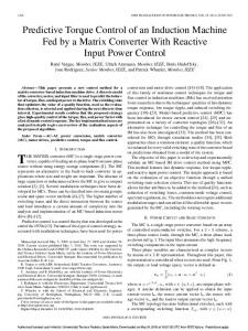
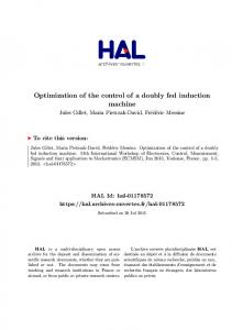
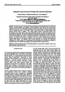
Based on the control strategy discussed above, Fig. 2 shows an implementation of the overall control system, which enables the slip power recovery system to function as both a VSCF generating system and a reactive power compensator. Individual control of the rotor inverter and of the grid side inverter and related feedback between the two inverters are shown Fig. 2. A current-regulated pulse width modulation voltage source inverter provides field oriented currents iqr and idr to the rotor circuit, controlling active Power and stator reactive power, respectively. Active Power command is given by the turbine optimal torque speed profile and reactive power command is calculated to minimize the machine copper losses. Overall active power generated is directly related to the torque, as indicated by (5) and (6).Another voltage source inverter is used to interface with the power network. In the same d-q reference frame as determined by the machine stator flux, its currents iql and idl are also field oriented, controlling Active and Reactive power of grid (Pgrid and Qgrid) respectively. Therefore, as discussed earlier, Pgrid is controlled through Iql to stablize the dc bus voltage and Qgrid is controlled through idl to meet the overall reactive power command.
IV. CONTROL ALGORITHM
Figure 2. Vector control strategy of DOIG
V. SIMULATION RESULTS AND DISCUSSION
The control model used in this study incorporates a conventional two-axis model of the doubly-fed machine into a field-orientated scheme using vector approach. The generator active and reactive power is used as the
Authorized licensed use limited to: NATIONAL INSTITUTE OF TECHNOLOGY ROURKELA. Downloaded on April 21, 2009 at 00:06 from IEEE Xplore. Restrictions apply.
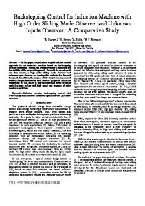
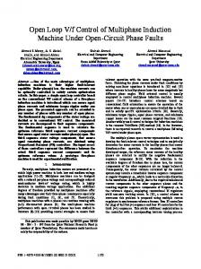
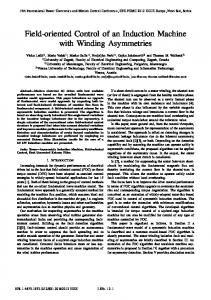
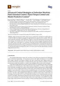
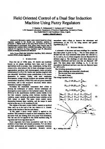
reference control parameters. In the IG mode, a conventional field-orientated scheme [12-14] is also used but it is adapted to reflect the fact that the converter supply is connected to the rotating rotor rather than a conventional stator connection. Fig. 3 & Fig. 4 illustrate the stator voltage for the doubly-fed connection over a speed range increasing from the normal generator synchronous speed of 1500rpm and d-q rotor voltages. It is clear from this figure that constraining the stator reactive power results in a small increase in the turbine speed but a more significant increase in the rotor current id. This additional current has to be provided by the rotor converter and is needed to inject reactive power into the rotor to ensure stator active power as shown in Fig. 9. The rotor current in this case however remains relatively constant as the speed increases. The rotor voltage on the other hand is determined mainly by the rotor speed and increases linearly as the rotor slip increases, or speed reduces. This is an important factor in determining the rating of the rotor converter. A detailed set of simulated results using dynamic vector control models were undertaken over a speed range from approximately 10% below synchronous speed (1500 rpm) to 40% below. Fig. 5 illustrates the electromagnetic torque of the DOIG during generating. Again there is a close correlation between the steady-state model and the simulated results using the dynamic control model. It is evident that the search for maximum grid power results in a reducing rotor voltage as the speed reduces. This particular operational feature is important and is due to the constraint that the air gap flux is maintained below the rated value to avoid over-fluxing the machine. In this case as the speed reduces, the rotor supply frequency reduces to keep the slip low and as a result the terminal voltage also reduces to avoid saturating the magnetizing paths in the generator. Fig. 7 illustrates the simulated results of rotor active power vs. reactive power using dynamic vector model described in the previous section. The correlation with the steady-state model results is on the whole very good. In fact at the higher speeds the DOIG produces slightly more power. The benefits would therefore appear to lie in the rotor converter ratings. The overall rating of the converter is related to the required speed range, typically 30% of the generator rating as mentioned previously. However the VA converter rating would be translated into maximum current and voltage ratings of the switching devices in the converter.Fig.8 illustrates the stator reactive power due to control of d- axis component. Fig. 9 and 10 illustrates the response active and reactive power control on rotor sides respectively due to control of rotor d-q components.
Figure 3. Response of three-phase Stator voltages of DOIG
Figure 4. Response of d-q rotor voltage of DOIG
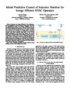
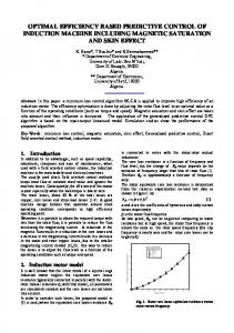
Figure 5. Response of Electro magnetic torque of the machine during generating mode
Authorized licensed use limited to: NATIONAL INSTITUTE OF TECHNOLOGY ROURKELA. Downloaded on April 21, 2009 at 00:06 from IEEE Xplore. Restrictions apply.
Figure 6. Stator current DOIG during motoring and generative mode of operation
Figure 10. Response of rotor reactive power of DOIG during step change in wind speed
VI. CONCLUSION
Rotor Qr versus Pr 1
0.8
0.6
0.4
0.2
0
-0.2
-0.4
-0.6
-0.8
-1
-1
-0.5
0
0.5
1
Figure 7. Response of rotor active power with respect to Reactive power
In this paper contribution, the induction machine is modeled in vectorized form in the synchronous frame. The d-axis is aligned with the stator space voltage vector. The injected rotor voltages (at slip frequency) are derived from PI controllers that regulate the active and reactive powers delivered by the generator. The speed is adjusted by the turbine pitch control to maximize the power generated at a given wind speed. It was shown that it is possible to develop a set of equations describing the behavior of the wind turbine. Furthermore, vector control strategy has been examined for controlling active and reactive power of grid, stator and rotor sides. The behavior of the system was investigated during step change in wind variations. This paper considers a grid-connected system; a further paper will describe a stand-alone system with experimental evaluation. APPENDIX 2-KW Induction wind turbine model parameters (Star equivalent circuit)
Figure 8. Response of stator reactive power for the step change in wind speed
Number of Pole Rated Speed Rated Voltage Rated Output Power Stator winding resistance
4 1800rpm 200 V 750 W 3.35 ohm
Stator leakage reactance Rotor resistance as referred to stator Rotor leakage reactance Rotor inertia Cut-in speed Vc
2.616 ohm 1.99 ohm 2.616 ohm 0.1 Kgm2 5.5 m/s
Rated speed VR Furling or cut-out speed VF Gear ratio K
11m/s. 20m/s 0.001
REFERENCES Figure 9. Response of active power of the rotor DOIG for the step change in wind speed
Authorized licensed use limited to: NATIONAL INSTITUTE OF TECHNOLOGY ROURKELA. Downloaded on April 21, 2009 at 00:06 from IEEE Xplore. Restrictions apply.
[1] I. Cadirci., & Ermi, “Double-output induction generator operating at sub synchronous and super synchronous speeds: steady-state performance Optimization and wind-energy recovery”, IEE Proceedings-B. 139, no.5, pp. 429-442, 1992. [2] S. Muller, M. Deicke and R.W. De Doncker, "Doubly fed induction generator systems for wind turbine", IEEE Industry Applications Magazine, Vol.8, No. 3, pp. 26-33, 2002. [3] R. Pena, J. C. Clare and G. M. Asher, "Doubly fed induction generator using back-to-back PWM converts and its application to variable speed wind-energy generation", IEE Proceedings Electrical Power Application, Vol. 143, No.3, pp. 231-241, May 1996. [4] A.Tapia, G.Ostolaza and J.X. Saenz, "Modeling and control of a wind turbine driven doubly fed induction generator", IEEE Transactions on Energy Conversion, Vol. 18, pp. 194- 204, June 2003. [5] Yazhou Lei, Alan Mullane, Gordon Lightbody, and Robert Yacamini “Modeling of the Wind Turbine With a Doubly Fed Induction Generator for Grid Integration Studies”, IEEE Transactions on Energy Conversion, Vol.21, no.1, pp. 257-264, March 2006. [6] Lucian Mihet-Popa, Frede Blaabrierg, “Wind Turbine Generator Modeling and Simulation Where Rotational Speed is the Controlled Variable”, IEEE Transactions on Industry Applications, Vol. 40 No.1, January/February 2004. [7] Dr Sandy Smith, Rebecca Todd and Dr Mike Barnes “Improved Energy Conversion for Doubly- Fed Wind Generators”, Proceedings of IAS 2005, pp. 7803-9208, June 2005. [8] J.G. Slootweg, H. Polinder and W.L. Kling “Dynamic Modeling of a Wind Turbine with Doubly Fed Induction Generator”, Proceedings of IEEE 2001. [9] M. S. Vicatos and J. A. Teqopoulos, “Steady state analysis of a doubly-fed induction generator under synchronous operation,” IEEE Trans. Energy Convers., vol. 4, no. 3, pp. 495–501, Sep. 1989. [10] J. G. Slootweg, H. Polinder, and W. L. Kling, “Dynamic modeling of wind turbine with doubly fed induction generator,” in Proc. IEEE Power Eng. Soc. Summer Meeting, Vancouver, BC, Canada, pp. 15–19, July 2001. [11] B.H.Chowdhary, Srinivas Chellapilla, “Doubly-fed induction generator for variable speed wind power generation” Transactions on Electric Power System Research, Vol.76,pp. 786-800, Jan 2006. [12] S.N.Bhadra, S.Banergee, “Wind Electrical Systems”, Oxford University Press, 2005.
Authorized licensed use limited to: NATIONAL INSTITUTE OF TECHNOLOGY ROURKELA. Downloaded on April 21, 2009 at 00:06 from IEEE Xplore. Restrictions apply.