610
L. SUBRT, D. GRACE, P. PECHAC, CONTROLLING THE SHORT-RANGE PROPAGATION ENVIRONMENT USING ACTIVE FSS
Controlling the Short-Range Propagation Environment Using Active Frequency Selective Surfaces Ludek SUBRT 1, David GRACE 2, Pavel PECHAC 1 1
Dept. of Electromagnetic Field, Czech Technical University in Prague, Prague, Czech Republic 2 Dept. of Electronics, University of York, York, United Kingdom
[email protected],
[email protected],
[email protected]
Abstract. This paper deals with a new approach to the control of the propagation environment in indoor scenarios using intelligent walls. The intelligent wall is a conventional wall situated inside a building, but equipped with an active frequency selective surface and sensors. The intelligent wall can be designed as a self-configuring and self-optimizing autonomous part of a collaborative infrastructure working within a high-capacity mobile radio system. The paper shows how such surfaces can be used to adjust the electromagnetic characteristics of the wall in response to changes in traffic demand, monitored using a network of sensors, thereby controlling the propagation environment inside the building. Some of the potential problems (mainly controlling coverage and interference) relating to an increased usage of wireless systems both inside and outside buildings are discussed and possible solutions using intelligent walls with the active FSS are suggested. The positive influence of intelligent walls on system performance is shown and results obtained from the simulations are shown and discussed.
Keywords Frequency Selective Surfaces (FSS), cognitive networks, intelligent infrastructure, indoor propagation modeling.
1. Introduction In the 21st century, wireless technologies [1-3] used inside buildings are starting to play a very significant role in our lives. At present, public properties like shopping centers and offices are mostly covered by 3G and GSM networks, DVB-T transmissions, and more and more by WI-FI network signals. Usage of these services will continue to increase rapidly, meaning that there will hardly be a public place where such transmissions cannot be received. This will be especially true inside buildings, and for this reason, it will put stress on an efficient system design and will also require innovative solutions which make these systems sufficiently clever in order to achieve adequate coverage, while maintaining high power and bandwidth efficiencies.
The purpose of this paper is to show a possible way to increase the indoor mobile system efficiency by creating a cognitive environment. The method is based on improved control of the propagation environment taking advantage of the fact that the local infrastructure can be cognitive as well as the communication devices themselves. This is achieved through the development of ‘intelligent’ walls, which can dynamically control their electromagnetic behavior in response changes in the way the communication devices are operating. This paper will consider two different issues – controlling the quality of coverage inside buildings and avoiding interference from devices sharing the same frequency. The effect of the intelligent walls will be illustrated by simulation of behavior in several usage scenarios. An intelligent wall is an active wall used in an indoor scenario that is and covered by an active Frequency Selective Surfaces (FSS). Thanks to the active FSS the wall is able to adjust its transmission and reflection characteristics depending on the traffic demand from the devices inside or outside the buildings. It can attenuate (or reflect) an impinging electromagnetic wave at a certain frequency, while having a minimized effect on the rest of the frequency band. We can take advantage of this feature to solve some issues related to the propagation phenomena inside buildings. The principle and main characteristics of the intelligent walls will be outlined in section 2. It is widely known that the behavior of electromagnetic waves inside buildings is mainly given by both building geometry and material properties of building components (walls, floors, ceilings, etc.). The FSS in the form of thin films could be even retrofitted to building walls making it possible to improve system performance in existing buildings. Let us consider two common situations that happen both inside and outside of a typical office building in a city: 1. Let us assume the situation when users that are operating mobile devices move inside a building. For example, when a meeting takes a place in a certain part of the building, most of the users are clustered in a room, while the rest of the building may remain comparatively empty. In such circumstances it is better to provide a better quality of coverage to the area where there is a high user
RADIOENGINEERING, VOL. 19, NO. 4, DECEMBER 2010
density, thus providing a higher quality of service. On the other hand, in the area where there are fewer users (or users with low priority) their coverage can be delivered at a lower quality level. Under such conditions one may expect the best overall performance for the combined system. One possible way to direct energy coming from a transmitting antenna to the area of high demand is to use the intelligent walls, as will be shown later. 2. As the number of wireless services increases there is an increasing need for improved coexistence [2]. Even today, we find a lot of wireless services coexisting inside office buildings. The coexistence of these services can cause serious problems. They can be a source of interference both inside and outside of a building, and additionally the emission of radio signals out of the building may not be appropriate for security reasons. To avoid the interference, the building walls can be shielded (including inner walls) using intelligent walls. This paper is divided into five sections. Section 2 deals with the active frequency selective surfaces and the resultant intelligent walls. The third section briefly mentions an indoor propagation model used during modeling and describes the simulation set up. The fourth section describes the simulation results obtained for the selected scenarios. In the last section, the new findings are summarized and possible future applications of the concept are presented.
2. Intelligent Walls The intelligent wall is considered as a self-configuring and self-optimizing part of a pre-installed collaborative autonomous infrastructure. This infrastructure can use distributed artificial intelligence (DAI) to help dynamically control a FSS enabling multipath propagation to be better controlled and energy focused towards certain parts of the building (while avoiding directing interference to an electromagnetically-sensitive area). The cognitive system managing the infrastructure consists of a distributed antenna structure, an intelligent wall structure and sensors and uses the DAI together with other principles and algorithms of the cognitive radio [4] (machine learning, spectrum sensing etc.) to achieve the best system performance. Such system can be fully autonomous and therefore managed without human intervention. The active FSS is the most important part of an intelligent wall. There is a significant body of work focusing on both passive and active FSS [5-7] so we will restrict our discussion to the most fundamental aspects. A large number of different types of FSS were already presented in [5], but typically it is a periodic planar structure providing spatial and narrowband frequency filtering of incident electromagnetic waves and can be used in many different applications. The passive FSS in contrast to the active
611
(adaptive) ones are designed to give a static frequency response. On the other hand the active FSS is able to adjust its electromagnetic characteristics dynamically. One possible way to control the active FSS characteristics is to use incorporated PIN diodes connecting metal parts of the FSS which are switched on and off by an external bias. An example of the FSS without the wall substrate was presented in [6], and this active FSS was designed at the frequency of 2.3 GHz. At this frequency, if the bias of the diode is set to OFF (OFF state) we can obtain a surface which is almost transparent, i.e. almost all impinging energy passes through the FSS – the transmission and insertion loss is nearly zero. If diodes are switched on (ON state), high isolation is achieved and in the example surface types used here the majority of impinging energy is reflected, and the isolation level is about 25 dB (transmission loss is therefore 25 dB). The values of transmission loss (0 dB for OFF and 25 dB for ON state) have been used for the modeling and simulations (see section 3). Another paper [8] deals with a frequency-selective (FS) wall that is a common partition wall with a band-stop frequency selective surface attached. The FS wall is placed in the main propagation path between the transmitter and receiver, each of which is placed in adjacent rooms at a distance of 2 m from each other in an office building. The paper shows that the difference in received power between the wall without FSS and the FS wall at the resonant frequency (5.8 GHz) is about 10-15 dB. Further, it shows that the FS wall frequency response is relatively insensitive to varying incidence angles (similar to the results presented in [9]). The relatively low difference between the wall and the FS wall is caused mainly by the multi-path character of the scenario. Multiple walls in the complex office building scenario cause multiple reflections and diffractions and therefore allow the signal to pass by the FS wall. Unlike the previously mentioned papers, our work is not primarily focused on the FSS itself, but on the concept of a controlling propagation environment. In our simulations the far field propagation is considered only, i.e. near field effects of the electromagnetic structures forming the FSS are neglected. A full electromagnetic simulator would have to be used to comprehensively model these issues. However, the near field effects will be significant only in the immediate vicinity of the FSS walls so it does not influence our general results. As was mentioned previously, the intelligent walls can potentially be a very powerful instrument to affect propagation environments inside indoor scenarios. We now discuss a typical set of parameters that can be used to describe the intelligent wall, made up of conventional wall and active FSS, and describe their function briefly. It must be recognized that precise derivation of material properties must take into account such things as angle of arrival of the incident wave, its polarization, the width of walls, their material constants, etc. The precise material constants inside real buildings are not usually known and therefore must be estimated.
612
L. SUBRT, D. GRACE, P. PECHAC, CONTROLLING THE SHORT-RANGE PROPAGATION ENVIRONMENT USING ACTIVE FSS
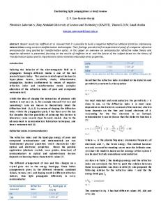
3. Propagation Model and Simulation Set up A site-specific 3D ray-based deterministic propagation model [10, 11] was used during simulations. The model considers the structure of a scenario as well as the electromagnetic parameters of the walls. It is able to provide the site specific prediction of both narrowband and wideband channel parameters (signal level, angle of arrival, impulse response prediction etc.). We have chosen a typical scenario for the simulations – a floor inside an office building. The scenario consists of 27 obstacles – 25 walls, the floor and ceiling. We only consider major obstacles, minor obstacles like furniture and people were neglected. Each obstacle used in modeling has its own set of parameters depending on its material type, its width and roughness of the surface. All indoor walls in the scenario are considered to be intelligent, meaning that their properties can be changed dynamically. Parameters used during the modeling are depicted in Tab. 1. In our simulations, we have focused both on control of coverage and interference. For our purposes, the floor was divided into three parts according to the function of each area (Fig. 1), namely the Office area – consisting of 10 offices divided into two parts, the Main office area consists of 3 rooms and the Meeting area is formed by 4 rooms. An omnidirectional transmitting antenna was placed in the Main office area as depicted in Fig. 3.
immediate demands using data obtained by network sensing (the position of users, their priority, etc.) or manually: Working Mode – In this mode, all the rooms in the scenario excluding the Meeting area and the corridor should be covered by the signal transmitted by the antenna. This mode corresponds to the situation when all users are present in the offices and nobody is present in the Meeting area. Meeting Mode – This represents the situation when all users are present in the Meeting area, meaning that the Meeting area should be well covered in contrast to the Office area. Meeting and Working Mode – This mode is used if both the Office area and the Meeting area need to be covered. The number of users presented in the Meeting area is much higher than the number in the Office area and therefore their priority (better signal to noise ratio) should be higher. The essential concept of cognitive networks is based on utilization of cognitive devices and infrastructure, the artificial intelligence, sensing and learning algorithms and offers a big potential for the future research.
4. Results 4.1 Calculation Method All scenarios were simulated using a software tool implementing the previously mentioned 3D ray-based deterministic model [10, 11]. The following algorithm was used. Firstly, the signal level (Fig. 2a) in each point of the scenario was predicted using deterministic algorithm. The exact positions of the transmitting antenna, obstacles and their material properties (depicted in Tab. 1) depending on the material, width, roughness as well as the presence of the FSS were taken into account during the prediction.
Fig. 1. A floor divided into three main parts.
The purpose of this paper is to investigate how the intelligent walls are able to better control the coverage provided by the antenna and consequently increase the performance of a cognitive network [4, 12, 13]. A cognitive network (definition taken from [12]) is a network with a cognitive process that can perceive current network conditions, and then plan, decide, and act on those conditions. The network can learn from these adaptations and use them to make future decisions, all while taking into account end-to-end goals. Our goal is to show a potential of using intelligent walls for the cognitive networks while the cognitive network itself and corresponding intelligence are not addressed. Let us define 3 different sample modes named according to the location of the majority users. The modes can be chosen by the cognitive network in dependence on
The values in the table (OFF states) were estimated from available values in literature and used as input data for a ray-launching class of propagation models. The values corresponding to ON states were estimated as a combination of the common wall and the FSS. Signal coverage in complex indoor scenarios is influenced by many phenomena (multiple reflections and diffractions) and therefore, at this level of concept verification, there is no need to rigorously model the FS wall behavior (i.e. by using an EM field simulator). The signal to noise ratio (the signal to interference ratio, respectively) was computed and the corresponding modulation scheme was determined (Fig. 2b) according to Tab. 2 [14]. The available modulation scheme in each room was determined considering the condition that at least 95% of the room must be covered by the certain modulation scheme (Fig. 2c).
RADIOENGINEERING, VOL. 19, NO. 4, DECEMBER 2010
613
Part of building
Material
Thickness [cm]
Enclosure wall
Concrete
Heavy wall
Transmission Loss [dB]
Reflection Loss [dB]
OFF
ON
OFF
ON
30
17.3
42.3
7.5
6.9
Concrete
10
6.9
31.9
7.5
4.2
Light wall
Plaster Board
5
2.2
27.2
12.9
1.8
Floor and Ceiling
Concrete
10
6.9
31.9
7.5
4.2
Tab.1. The intelligent walls parameters (ON and OFF state).
MSCH (Code Rate)
min. SINR [dB]
MSCH (Code Rate)
min. SINR [dB]
BPSK (1/2)
1
QPSK (1/1)
12.5
BPSK (2/3)
3
64QAM (1/2)
15.1
BPSK (3/4)
3.8
16QAM (2/3)
17.7
BPSK (7/8)
4.8
16QAM (1/1)
19.7
QPSK (3/4)
6.8
BPSK (1/1)
9.5
64QAM (1/1)
26
The results of the Meeting and Working Mode can be seen in Fig. 3d. The best quality of coverage is reached for the Meeting area as was requested. The Office area is covered as well as the meeting area but with the lower level of modulation scheme than in the case of the Meeting area – according to our request. There are also other issues arising from this approach. Other mobile communication services working in close frequency bands (GSM, UMTS) can be affected by the intelligent wall system. This can cause problems if, for example, a mobile device is connected to the outdoor cellular network.
Tab.2. SINR and corresponding modulation schemes.
Fig. 2. The determination of the available modulation scheme.
4.2 Controlling Coverage Fig. 3 shows the results obtained by the above mentioned process. In Fig. 3a you can see the scenario in the static mode (all intelligent walls are set to OFF). It corresponds to the conventional buildings.
Fig. 3. Four modes of the coverage controlling.
4.3 Interference Controlling
The quality of coverage predicted using the Working Mode is depicted in Fig. 3b. In this case, the Meeting area is completely shielded from the transmitter and almost all energy is reflected by its peripheral intelligent walls which are in ON state. The reflected energy can be therefore used for reaching the better quality of coverage of the Office and Main office area – the Office area is covered better than in the static mode.
If four transmitters working at the same frequency are placed in the corners of the scenario (Fig. 4 – Multipletransmitter configuration), we can expect that the quality of coverage will be limited because of interference among the transmitters. To avoid this effect and to minimize the size of uncovered area and therefore to increase quality of coverage and increase system capacity we can switch on suitable intelligent walls as can be observed in Fig. 4.
The available modulation schemes predicted for the Meeting Mode are displayed in Fig. 3c. As you can see the whole meeting area is covered by the best modulation scheme in contrast to the static mode. Office areas (except two rooms) are not covered.
Fig. 4a shows the quality coverage (predicted using the process mentioned in section 4.1) when no intelligent walls are active. You can see a large uncovered area (white color) caused by interference from the transmitters by contrast to the situation depicted in Fig. 4b showing coverage
614
L. SUBRT, D. GRACE, P. PECHAC, CONTROLLING THE SHORT-RANGE PROPAGATION ENVIRONMENT USING ACTIVE FSS
when four suitable intelligent walls are set to ON. In the first case (Fig. 4a), there are only 10 rooms covered. In the second case (Fig. 4b), the entire scenario (except the corridor, i.e. 17 rooms) is covered. That means we can achieve about 42 % larger size of the covered area than in the case of the static mode. The control of interference allows us to achieve a higher system capacity (higher data speed rate), to decrease the transmitter power level (extend battery life of mobile devices) and avoid interference to electromagnetically-sensitive areas.
References [1] GOLDSMITH, A. Wireless Communications. Cambridge University Press, 2005.
New
York:
[2] PATRICK, D., MORROW, R. Wireless Network Coexistence. McGraw-Hill Professional, 2004. [3] SAUNDERS, S., ARAGON, A. Antennas and Propagation for Wireless Communication Systems. Wiley & Sons, 2007. [4] MITOLA, J. Cognitive Radio Architecture. New York: Wiley & Sons, 2006. [5] MUNK, B. A. Frequency Selective Surfaces: Theory and Design. Wiley & Sons, 2000. [6] CHANG, K., SANG, K., JOONG, Y. Y. Equivalent circuit modeling of active frequency selective surfaces. In Radio and Wireless Symposium, 2008, p. 663-666. [7] KIANI, G. I., ESSELLE, K. P., WEILY, A. R., FORD, K. L. Active frequency selective surface using PIN diodes. In Antennas and Propagation Society Int. Symposium. 2007, p. 4525-4528.
Fig. 4. Multiple-transmitter configuration.
5. Conclusion We have proposed a new method of controlling signal coverage which can be used inside buildings both for coverage controlling and avoiding of interference between transmitters. The method is based on changing of electromagnetic properties of intelligent walls which are conventional walls equipped with an active frequency selective surface and sensors. The walls are part of a collaborative autonomous infrastructure and they are able to adjust their properties, e.g. on the basis of data obtained by sensing of users or cognitive network sensing. The sample scenario was modeled and simulated to demonstrate the principle of the idea and function of the intelligent walls. The results show that intelligent walls can be strong instrument to control signal coverage and subsequently to control available level of service. The controlling of coverage is very useful when mobile users change their position in an indoor scenario, because then intelligent walls provide the efficient way to change propagation environment rapidly.
Acknowledgements This work was supported in part by the Czech Ministry of Education, Youth and Sport project no. OC10005 "Intelligent Infrastructures for Cognitive Networks" in the frame of the COST Action IC0902.
[8] SUNG, G. H. H., SOWERBY, K. W., NEVE, M. J., WILLIAMSON, A. G. A frequency-selective wall for interference reduction in wireless indoor environments. IEEE Antennas and Propagation Magazine, 2006, vol. 48, p. 29-37. [9] TEO, P. T., LUO, X. F., LEE, C. K. Transmission of convoluted periodic loop element with selective reflection. Applied Physics Letters, 2004, vol. 85, p. 1454-1456. [10] PECHAC, P., KLEPAL, M. Effective indoor propagation predictions. In Vehicular Technology Conference. 2001, p. 12471250. [11] SUBRT, L., PECHAC, P. Semi-deterministic propagation model for subterranean galleries and tunnels. IEEE Transactions on Antennas and Propagation, Accepted May, 2010. [12] RYAN, W. T., DANIEL, H. F., LUIZ, A. D., ALLEN, B. M. Cognitive networks: adaptation and learning to achieve end-to-end performance objectives. IEEE Communications Magazine, 2006, vol. 44, p. 51-57. [13] THOMAS, R. W., DASILVA, L. A., MACKENZIE, A. B. Cognitive networks. In First IEEE International Symposium on New Frontiers in Dynamic Spectrum Access Networks DySPAN 2005. 2005, p. 352-360. [14] HUINING, H., YANIKOMEROGLU, H., FALCONER, D. D., PERIYALWAR, S. Range extension without capacity penalty in cellular networks with digital fixed relays. In IEEE Global Telecommunications Conf. GLOBECOM '04. 2004, p. 3053-3057.
About Authors ... Ludek SUBRT received the M.Sc. degree in Radio Electronics from the Czech Technical University in Prague in 2008. He is currently a Ph.D. student in the Dept. of Electromagnetic Field at the same university. His current research interests are focused on radio wave propagation modeling, smart environments and cognitive radio. David GRACE received his MEng degree in Electronics Systems Engineering and DPhil in Electronics from the University of York in 1993 and 1999 respectively. He is currently Head of the Communications Research Group at
RADIOENGINEERING, VOL. 19, NO. 4, DECEMBER 2010
the University of York. His research interests are in the areas of cognitive communications, including the sub-areas cognitive radio and cognitive networks. He was the instigator and now chairs the Worldwide Universities Network Cognitive Communications Consortium, a global grouping of 40 academic and industrial organizations.
615
Pavel PECHAC received the M.Sc. degree and the Ph.D. degree in Radio Electronics from the Czech Technical University in Prague in 1993 and 1999 respectively. He is currently a Professor in the Dept. of Electromagnetic Field at the same university. His research interests are in the field of radiowave propagation and wireless systems.
RADIOENGINEERING REVIEWERS December 2010, Volume 19, Number 4
AL-SCHERBAZ, A., University of Buckingham, UK
CHENG, L., Trinity College, Hartford, USA
AHN, C.-J., Chiba University, Japan
ČECHÁK, J., University of Defense, Brno, Czechia
ARCE-DIEGO, J. L., University of Cantabria, Santander, Spain
ČERNOCKÝ, J., Brno University of Technology, Czechia
ARTHABER, H., Vienna University of Technology, Austria
ČERNÝ, P., Czech Technical University in Prague, Czechia
BALLING, P., Antenna Systems Consulting ApS, Denmark
DIET, A., Université Paris Sud, France
BALTZIS, K., Aristotle University of Thessaloniki, Greece
DOBEŠ, J., Czech Technical University in Prague, Czechia
BEČVÁŘ, Z., Czech Technical University in Prague, Czechia BEŠŤÁK, R., Czech Technical University in Prague, Czechia BEZPALEC, P., Czech Technical University in Prague, Czechia BIOLEK, D., University of Defense, Brno, Czechia BLUMENSTEIN, J., Brno University of Technology, Czechia BOBULA, M., RACOM Company, Czechia BONEFAČIĆ, D., University of Zagreb, Croatia BORTEL, R., Czech Technical University in Prague, Czechia BRANČÍK, L., Brno University of Technology, Czechia BURDA, K., Brno University of Technology, Czechia
DIMITRIJEVIĆ, B., University of Niš, Serbia
DVOŘÁK, J., Brno Univ. of Technology, Czechia DŘÍNOVSKÝ, J., Brno University of Technology, Czechia FEDRA, Z., Brno University of Technology, Czechia FISCHER, M., Vienna University of Technology, Austria FIŠER, O., Academy of Sciences of the Czech Republic, Prague, Czechia FLIEGEL, K., Czech Technical University in Prague, Czechia FONTAN, P. F., University of Vigo, Spain FRANEK, O., Aalborg University, Denmark FRÝZA, T., Brno University of Technology, Czechia FUČÍK, O., Brno University of Technology, Czechia GALAJDA, P., Technical University of Košice, Slovakia
616
RADIOENGINEERING REVIEWERS
GEORGIADIS, A., Centre Tecnologic de Telecomunicacions de Catalunya, Barcelona, Spain
MARŠÁLEK, R., Brno University of Technology, Czechia
GREGORIO, F., Universidad Nacional del Sur, Argentina
MARTÍNEK, P., Czech Technical University in Prague, Czechia
GRGIĆ, S., University of Zagreb, Croatia
MILOŠEVIĆ, N., University of Niš, Serbia
HAJNÝ, J., Brno University of Technology, Czechia
MINAEI, S., Dogus University, Turkey
HAZDRA, P., Czech Technical University in Prague, Czechia
MOHR, F., Pforzheim University, Germany
HEKRDLA, M., Czech Technical University in Prague, Czechia HENNIGER, H., German Aerospace Center, Germany HORNG, J.-W., Chung Yuan Christian University, Taiwan HOZMAN, J., Czech Technical University in Prague, Czechia
MOLNÁR, K., Brno University of Technology, Czechia NAGY, J., Brno University of Technology, Czechia NIKOLIĆ, Z., University of Niš, Serbia NOVOTNÝ, V., Brno University of Technology, Czechia OZOGUZ, S., Istanbul Technical University, Turkey
KEJÍK, P., Brno University of Technology, Czechia
PÁTA, P., Czech Technical University in Prague, Czechia PETRŽELA, J., Brno University of Technology, Czechia POKORNÝ, M., Brno University of Technology, Czechia POLÍVKA, M., Czech Technical University in Prague, Czechia
KESKIN, A. U., Yeditepe University, Istanbul, Turkey
POLEC, J., Slovak University of Technology, Bratislava, Slovakia
KOCÚR, D., Technical University of Košice, Slovakia
POVALAČ, A., Brno University of Technology, Czechia POVALAČ, K., Brno University of Technology, Czechia PROKEŠ, A., Brno University of Technology, Czechia PROKOPEC, J., Brno University of Technology, Czechia
HUDEC, P., Czech Technical University in Prague, Czechia JALOVECKÝ, R., University of Defense, Brno, Czechia JÄNTTI, R., Aalto University, Finland
KOLKA, Z., Brno University of Technology, Czechia KOUDELKA, V., Brno University of Technology, Czechia KOLÁŘ, R., Brno University of Technology, Czechia KOVÁŘ, P., Czech Technical University in Prague, Czechia KUBÍČEK, M. Brno University of Technology, Czechia KULLA, P., Slovak University of Technology, Bratislava, Slovakia KVIČERA, M., Czech Technical University in Prague, Czechia KVIČERA, V., Czech Metrology Institute, Czechia LAHIRI, A. Netaji Subhas Institute of Technology, New Delhi, India LAKKUNDI, V., FORTH-ICS, Heraklion, Greece LAMI, I., University of Buckingham, UK LÁČÍK, J., Brno University of Technology, Czechia LUKEŠ, Z., Brno University of Technology, Czechia MACHÁČ, J., Czech Technical University in Prague, Czechia MASO, M., Supélec, Metz, France
PUNČOCHÁŘ, J., VŠB - Technical University of Ostrava, Czechia RABOCH, J. Czech Technical University in Prague, Czechia RAIDA, Z., Brno University of Technology, Czechia RAJMIC, P., Brno University of Technology, Czechia SCHEJBAL, V., University of Pardubice, Czechia SCHIMMEL, J., Brno University of Technology, Czechia SEGOVIA-VARGAS, D., Carlos III University of Madrid, Spain SIGMUND, M., Brno University of Technology, Czechia SLANINA, M., Brno University of Technology, Czechia SMÉKAL, Z., Brno Univ. of Technology, Czechia
RADIOENGINEERING, VOL. 19, NO. 4, DECEMBER 2010
617
SOLIMAN, A., Cairo University, Egypt
VALENTA, V., ESIEE Paris, France
SZABÓ, Z., Czech Technical University in Prague, Czechia
VALTR, P., European Space Agency, Netherlands
ŠEBESTA, J., Brno Univ. of Technology, Czechia
VENARD, O., ESIEE Paris, France
ŠEBESTA, V., Brno Univ. of Technology, Czechia ŠEDĚNKA, V., Brno University of Technology, Czechia ŠEDIVÝ, P., RETIA company, Czechia ŠILHAVÝ, P., Brno University of Technology, Czechia ŠIMŠA, J., Academy of Sciences of the Czech Republic, Prague, Czechia ŠOTNER, R., Brno Univ. of Technology, Czechia
VÁGNER, P., Brno Univ. of Technology, Czechia VIŠČOR, I., Academy of Sciences of the Czech Republic, Brno, Czechia VLČEK, Č., University of Defense, Brno, Czechia VOJTĚCH, L., Czech Technical University in Prague, Czechia VODRÁŽKA, J., Czech Technical University in Prague, Czechia WIESER, V., University of Žilina, Slovakia
ŠRÁMEK, P., Brno Univ. of Technology, Czechia
WILFERT, O., Brno University of Technology, Czechia
ŠVIHLÍK, J., Institute of Chemical Technology in Prague, Czechia
YANNOPOULOU, N., Democritus University of Thrace, Greece
TSANKOV, B., Technical University of Sofia, Bulgaria
ZELINKA, P., Brno University of Technology, Czechia
UHLEMAN, E., Halmstad University, Sweden
ZHANG, H., Zhejiang University, China
ULOVEC, K., Czech Technical University in Prague, Czechia
ZHANG, L., Harbin Institute of Technology, China
UŘIČÁŘ, T., Czech Technical University in Prague, Czechia VACULÍK, M., University of Žilina, Slovakia
ZIMOURTOPOULOS, P., Democritus University of Thrace, Greece ZVÁNOVEC, S., Czech Technical University in Prague, Czechia