IEEE TRANSACTIONS ON CIRCUITS AND SYSTEMS FOR VIDEO TECHNOLOGY, VOL. 13, NO. 11, NOVEMBER 2003
1129
Creating and Encoding of Cartoons Using MPEG-4 BIFS: Methods and Results Cyril Concolato, Jean-Claude Dufourd, and Jean-Claude Moissinac
Abstract—Our work focuses on the encoding of two–dimensional (2-D) graphics animated cartoons with MPEG-4. This stems from a need to stop encoding cartoons as videos and to start using methods more adapted to animated 2-D vector graphics sequences. We expected this could be an efficient coding with good versatility for various types of terminals. First, we present some technical specification for such cartoons. Next, we give an overview of MPEG-4 BIFS encoding methods. Then, we analyze how to optimize the use of these methods; some of our proposals could be useful for 2-D graphics applications other than animated cartoon. Last, we show some results with significantly better encoding efficiency over simple BIFS encoding. Index Terms—Cartoon design, efficient coding, MPEG-4 BIFS, two–dimensional (2-D) vector graphics.
I. INTRODUCTION
T
HE demand for two–dimensional (2-D) animated graphics is growing rapidly. There is a need for low-bit-rate and high-quality animations to be streamed over the Internet and the need is even direr over wireless networks (e.g., GPRS, UMTS). In particular, the need for efficient coding and streaming solutions for high-quality cartoons is real. As a response for this demand, many proprietary solutions [1] and many standards are being developed [2], [3]. One possibility is to code a cartoon or an animation as a video, but this solution lacks flexibility and presents some poor performance in the tradeoff between quality and bit rate. For low bit rates, a cartoon encoded with traditional video encoding techniques will present some coding artifacts. These artifacts are due to the use of transforms and quantization techniques that perform badly on high-frequency regions. This is the case of the kind of cartoons dealt with in this paper. They present a lot of discontinuity in colors because two neighboring shapes usually have different colors and the edge is also usually emphasized with a dark sharp line. 2-D vector graphics encoding, however, brings a lot of flexibility because an animation can be easily resized and adapted to the capabilities of the terminal. A 2-D vector graphics animation can even be customized for the user. We will see in this paper that vector coding is adapted to the coding of cartoons and graphics animation. Manuscript received November 2001; revised June 2003. C. Concolato and J.-C. Dufourd are with the Department of Telecommunication and Electrical Engineering, Ecole Nationale Supérieure des Télécommunications (ENST) of Paris, 75013 Paris, France (e-mail:
[email protected];
[email protected]). J.-C. Moissinac is with the Department of Computer Science and Networking, Ecole Nationale Supérieure des Télécommunications (ENST) of Paris, 75013 Paris, France (e-mail:
[email protected]). Digital Object Identifier 10.1109/TCSVT.2003.817363
One candidate for the encoding of cartoons is MPEG-4. While MPEG-2 was about the encoding of video and audio, MPEG-4 offers some tools for the encoding of multimedia scenes, including 2-D/three-dimensional (3-D) graphics. We will show in this paper that MPEG-4 provides good performance for the encoding of cartoons in terms of bit rate and quality. Moreover, MPEG-4 is an international standard and so this solution offers the benefits of interoperability. The same MPEG-4 standard is also about encoding of natural and synthetic audio and video and, therefore, enables easy integration and synchronization of all types of media. The remainder of this paper is organized as follows. Section II gives an overview of the cartoon design techniques. Section III gives an overview of the MPEG-4 BIFS standard, which is used for the encoding of vector graphics. Section IV describes how a mapping can be done between both sets of techniques and gives a discussion of various optimizations. Finally, Section V presents some experimental results. II. OVERVIEW OF CLASSIC CARTOON DESIGN TECHNIQUES Our work focused on the encoding of cartoons of a rather classic kind. In this section, we describe the hypotheses made on some features which are relevant for their efficient encoding. Classic cartoons like the ones produced by Disney, or of the style of Tex Avery, are generally made of a background on which some characters move. The traditional manner of composing pictures of such cartoons consists of drawing the background and the characters on different transparent celluloid sheets. Some sheets are then put on top of each other and filmed. A cartoon character is represented on several sheets that show different instants in time. The drawings are often very different from one sheet to another. As a consequence, the animation of the cartoon characters is not parametric. Further demonstrations on this topic can be found in [4]. The drawings representing the characters are generally made of zones of uniform colors and surrounded with a border line of a different color. The characters are drawn separately and their compositing is specified by the exposure sheet. The exposure sheet describes, for each frame, the way to compose the final picture. It describes the background to use and the how the celluloid sheets should be stacked on the top of the background. A short note indicates if an element of the previous frame is to be reused in the next one. From a technical perspective, this means that we can extract the following points from the exposure sheet: • a list of actions to perform for each frame: addition of a new element to be displayed, removal of an element
1051-8215/03$17.00 © 2003 IEEE
1130
IEEE TRANSACTIONS ON CIRCUITS AND SYSTEMS FOR VIDEO TECHNOLOGY, VOL. 13, NO. 11, NOVEMBER 2003
present in the previous frame, or transformation to apply to an element; • A list of elements which need to be referenced more than two times during the whole cartoon, and a list of elements which will be referenced only twice (display and removal). From the features of the classic cartoons that we have exposed in this section, we propose to study how they can be encoded using MPEG-4 BIFS. III. OVERVIEW OF THE MPEG-4 BIFS STANDARD In this section, we first present the MPEG-4 BIFS standard, followed by a description of the different encoding techniques offered by this standard used in this paper. A. BIFS and VRML MPEG-4 is an international standard defined by ISO/IEC for the encoding of interactive audio–visual scenes [3]. It defines the coded representation of audio–visual content [5], [6] as well as the coded representation of the spatio-temporal positioning of the audio–visual objects and their behavior in response to interaction. This latter representation is called Binary Format for Scenes (BIFS) and specified in Part 1 of the standard [7], [11], [12]. The structure of a BIFS scene has been mostly inherited from the VRML 2.0 (Virtual Reality Modeling Language) standard, which is also an ISO/IEC standard [8]. An MPEG-4 scene consists of a tree made of nodes of different types: time-dependent media (audio, video, BIFS), static media (still pictures, 2-D or 3-D graphics, grouping or transforming nodes) and events generator (interpolators or sensors). Each node has a set of parameters, called fields, whose values can be modified dynamically or interactively to change the behavior of the node. A BIFS scene or a VRML scene may contain a large amount of nodes. Therefore, to reduce redundancy of nodes, VRML has defined the following mechanisms: the DEF/USE commands and the PROTO concept. The DEF command allows to assign an ID (or a name) to a pattern of nodes. While the USE command allows to reuse this pattern elsewhere in the scene by just giving its ID or name. The PROTO concept is more elaborate, allowing the definition of a parametric pattern of nodes which can then be reused with different values of the parameters. A PROTO is defined by assigning an ID (or a name) and specifying the fields of the particular nodes as the parameters in this pattern. It is then instantiated as a regular node in the scene graph with the parameters (fields). We will see in Section IV that both mechanisms are extensively used for efficient encoding of cartoons. B. Improvements of BIFS Compared to VRML Even though BIFS is based on VRML, it adds some key features that are presented here: streamability and compression. 1) Streamability: The first feature that BIFS adds to VRML is the ability to cut a scene description in timed pieces of scene. Indeed, a BIFS scene can be updated at some points in time with two different mechanisms: BIFS Commands and BIFS Animation Frames. BIFS Commands allow to do any kind of modifications to the scene ranging from the update of the value of
a field to the insertion or deletion of a subtree of nodes. BIFS animation frames are more specific to parametric animations. They are used to regularly and continuously update the values of some fields of type: integer, float, rotation, color, 2-D or 3-D coordinates. 2) Compression: The second added feature of BIFS is compression. While VRML is a textual format, BIFS uses a compact binary format. A BIFS scene is coded by following a depth-first order scan of the tree of nodes and by encoding each node individually using a first-order contextual code. Each field of each node is then individually encoded depending on its type: boolean, float, integer, 2-D or 3-D coordinates, rotation, color, string, time. In case the DEF/USE and PROTO mechanisms are used, IDs are encoded on a different fixed number of bits. Moreover, BIFS Commands allow to use elaborated techniques to achieve even better compression: linear quantization (LQ), predictive and arithmetic coding, and efficient float coding for BIFS Commands; and arithmetic coding for BIFS Animation Frames. We will see in Section IV how these techniques match the requirements of cartoons encoding. • BIFS Commands LQ To perform LQ, a special node needs to be present in the scene. This node, called QuantizationParameter node, is signaled by its positioning to which subtree of the scene the quantization should apply. Furthermore, the fields of this node specify: to which type of fields the quantization should apply; on how many bits the values of those fields should be represented; and the maximum and minimum values. Moreover, LQ is performed on an update per update basis. This means that to update a part of the scene, which was quantized when created, if the content of the update needs to be quantized, then a QuantizationParameter node has to be put within the update. The following formula describes the quantization process and the inverse quantization process for all the cases except for angle and rotation quantization processes where a normalization step is needed:
LQ step
(1)
inverse quantization step
(2)
where represents the nonquantized value, represents and respectivley represent the quantized value, the minimum and maximum value that can take, and represents the number of bits on which the quantized value is represented. • BIFS Commands Predictive and Arithmetic Coding When encoding an array of values, one might want to exploit the correlation between the different values. The so-called PredictiveMFField encoding, used on top of the previous LQ step, performs a prediction step followed by an adaptive arithmetic coding (AAC) step. This technique, when used, adds a 1-bit flag to all the arrays of the scene
CONCOLATO et al.: CREATING AND ENCODING OF CARTOONS USING MPEG-4 BIFS
TABLE I DESCRIPTION OF THE EFFICIENT FLOAT CODING TECHNIQUE
which signals whether the array is just quantized or predicted and arithmetically coded. Since this technique depends on the presence of a QuantizationParameter node, it also work on a per-update basis. • BIFS Commands Efficient Float Coding Default BIFS encoding of floating-point values uses IEEE 754 32-bits format [9]. It is obvious that, in some cases, these 32 bits are not needed. Therefore, BIFS defines a variable length encoding for floats as follows. , After decoding the values of the parameters , , , , and according to Table I, the float value is then reconstructed as follows:
(3) Use of Efficient Float Coding is signaled through the useEfficientCoding field of a QuantizationParameter node and apply to a subtree of the scene as for the LQ. Again, the scope of this technique is an update. IV. CARTOON ENCODING OPTIMIZATIONS In Section IV-A, we first presented the type of cartoon we are interested in representing using MPEG-4 and the features of a BIFS scene for these cartoons. In Section IV-B, we discussed why some encoding techniques, presented in Section III, are applicable to the efficient encoding of these scenes. A. Working Assumptions From now on, we assume that the cartoons to be represented are of a rather classical kind, as described in Section II: 2-D drawings accumulated on a background, made of uniform colors generally surrounded with a border line of a different color. In the cartoons described in this paper, all the elements are either polygons filled with a uniform color and surrounded with an other color or polylines drawn with a uniform color. Hence, the major part of the description of these elements is a list of 2-D coordinates. The BIFS nodes that are used are the following: • OrderedGroup: to create a layered scene; • Background2D: to set the background properties like the color or the texture; • Transform2D: to translate, re-scale, and/or rotate some part of the scene;
1131
• QuantizationParameter: to apply LQ (see Section III-B.2); • Shape: to signal a graphical primitive; • Appearance: to describe the appearance of a shape; • Material2D: to describe the color, the fill of the shape; • LineProperties: to describe the width and color of the border of a shape; • Coordinate2D: to list the coordinates of the points composing the shape; • IndexedFaceSet2D: to signal that the shape is a face delimited by some points referenced directly or by the use of indexes; • IndexedLineSet2D: to signal that the shape is a line described by some points referenced directly or by the use of indexes. As described in Section III-B.1, BIFS offers two kinds of streams: BIFS Command and BIFS Animation Frame. As we have seen in Section II, classic cartoons cannot be represented using parametric animations, therefore the BIFS Animation Frame technique appeared not to be relevant. Therefore, this paper shows one representation of the described type of cartoons using only BIFS Commands. The initial BIFS scene is composed of a background on top of which are several layers. At regular intervals in time, depending on the frame rate, new Shape, Appearance and/or LineProperties nodes are placed in the appropriate layer. If a Shape, Appearance, or LineProperties node is to be reused somewhere else in the scene or at a different point in time, the node is given an ID (see Section III-A) and placed in the lists of Shape, Appearance and LineProperties nodes. These lists are present in the scene but not displayed. When a node of a list needs to be displayed, the USE command with its ID is then inserted in the appropriate layer. The target BIFS profiles for our cartoons are the Advanced2D scene graph profile and the Advanced2D Graphics profile. B. Effective Encoding Efficient coding of the type of cartoons that we described consist in efficiently coding both the structure of the scene and lists of 2-D points. 1) Encoding of the Structure: As a result of the use of BIFS commands, most of the updates consist in inserting two repetitive patterns of nodes in the scene. These patterns are made of: a Shape node, whose appearance field is an Appearance node and whose geometry field is either an IndexedFaceSet2D or IndexedLineSet2D node. In both cases, the face or line nodes contain, as coord field, a Coordinate2D node which lists, in its point field, a set of 2-D coordinates. Throughout the scene, only the appearance and the point fields change. Therefore, two PROTOs are created, one in case of IndexedFaceSet2D and one in case of IndexedLineSet2D. In both cases, the encoding of the pattern, without the Appearance node and the list of points, uses 30 bits. The definition of the corresponding PROTO takes 81 bits to which the number of bits to code a PROTO ID (protoIDbits) and the number of bits to code a node ID (nodeIDbits) must be added. Then, the instantiation of the PROTO, not taking into account the encoding of
1132
IEEE TRANSACTIONS ON CIRCUITS AND SYSTEMS FOR VIDEO TECHNOLOGY, VOL. 13, NO. 11, NOVEMBER 2003
TABLE II MAXIMUM LENGTH (IN BITS) OF RATIONALS REPRESENTED WITH EFFICIENT FLOAT CODING
the Appearance node and the list of points, consumes 14 bits plus protoIDbits. So, the equation is simple, PROTOs are worth using when
where is the number of repetitions of the structure in the scene. Since we need only two different PROTOs, protoIDbits equals to 1. This leads to a minimum number of occurrence of . Finally, the same structure of with the assumption that nodeIDBits will be less than 14, which nodes, PROTOs are useful for allows for assigning IDs to this structure if the structure is repeated more than seven times and the gain is then of 15 bits per repetition. In case the structure represents a polygon, this means particularly that the PROTO tool is worth being used when the scene contains more than seven polygons. Rule 0: Use PROTO when the number of repetitions of the . structure is more than the appropriate 2) Encoding of a List of Coordinates: In this section, we present and explain the rationales for the encoding tools that we used for encoding lists of coordinates. We also expose a list of rules to code cartoons but some of the rules can apply to other scenarios (3-D model coding, other 2-D graphic scenes). As all the techniques that we presented previously work on an update basis and as in our scenario each frame corresponds to an update, all the rules that we will expose are scoped by a frame. • Efficient Float Coding To evaluate the efficiency of this encoding tool, we analyze the results given when encoding the floats whose and whose integer part is comprised between 0 and . This range of floats fractional part is a multiple of seems to be relevant because the coordinates of the points th of pixels by 2-D are often given with a precision of graphics software. Hence, the float 998,25 would correand . spond to Table II represents the maximum number of bits needed and . Table III shows to code a float with respect to the average numbers of bits to code a float with respect to and . As we can see, the Efficient Float Coding tool is a simple compression tool which allows for reducing the number of bits needed to code a float. Since a cartoon scene contains a lot of floats (2-D coordinates), and since the cost in bits to signal the use of this encoding is limited (16 bits per frame), we can infer the following rule for cartoons encoding.
TABLE III AVERAGE LENGTH (IN BITS) OF RATIONALS REPRESENTED WITH EFFICIENT FLOAT CODING
Rule 1: For each frame, always set the Efficient Coding flag. A first direct consequence of this rule is that all the floats of the scene will need less bits to be coded, though this compression is not the best one as we will see. A second consequence, less trivial, is that the additional QuantizationParameter nodes will cost less, as we will see in the next paragraph. • LQ When encoding 2-D coordinates the QuantizationParameter node presented in Section III-B.2) is restricted to the following fields: • position2Dmin: a pair of floats for the minimum values for the and coordinate; • position2Dmax: a pair of floats for the maximum values for the and coordinate; • position2Dquant: a flag which activates the quantization for the subtree; • position2DnbBits: an integer which specifies the number of bits on which each 2-D coordinate will be represented. This raw encoding of such a QuantizationParameter node uses 198 bits. If this node is put in the scope of the QuantizationParameter node as recommended by Rule 1, then the same structure uses less than 171 bits. Indeed, under these conditions, since position2DnbBits ranges between 0–31, it is by default quantized on 5 bits and so saves 27 bits. Moreover, this number of bits can be reduced because the fields position2Dmin and position2Dmax can be coded using Efficient Float Coding. For example, if the coordinates are made of integers between 0–1024, then position2Dmin and position2Dmax are also between these bounds. So, each new QuantizationParameter node will only use 85 bits. When using LQ, not taking into account the cost in bits of the structure, the precise number of bits to code the same range of floats than the one used for computing Table II follows in Table IV. Assuming that there are more than 76 points in a frame, the cost of the structure per float is less than 1 bit. Therefore, LQ is always better than Efficient Float Coding. Rule 2: For each frame, always add a second QuantizationParameter node which sets the bounding box and coordinate precision of the frame. A consequence of Rule 2 is that each point in a frame —always 16 uses a constant number of bits. Let bits—be the cost of QuantizationParameter node from
CONCOLATO et al.: CREATING AND ENCODING OF CARTOONS USING MPEG-4 BIFS
1133
TABLE IV MAXIMUM LENGTH (IN BITS) OF RATIONALS REPRESENTED USING LINEAR QUANTIZATION
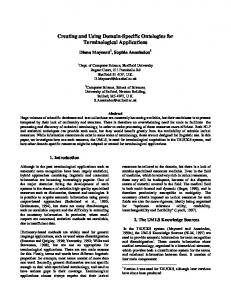
Fig. 1. Block diagram of PrectiveMFField coding.
Rule 1; let be the cost of QuantizationParameter be the number of points in the node from Rule 2; let frame, then the cost of each point in the scope of these QuantizationParameter nodes is (4) In order to evaluate the additional gain that a new QuantizationParameter node would bring, we now assume that we introduce a new node to quantize a part of the picture. be the cost of this QuantizationParameter node; Let be the number of points in this part of the frame, let be the difference between the position2DnbBits and fields of the 2 nodes. So, the additional cost for each point and the additional gain for each point is is (5) Equation (5) shows the conditions under which this new QuantizationParameter node brings additional encoding efficiency and gives the following new rule. , if (5) is satisfied, add the Rule 3: Depending on corresponding new QuantizationParameter node. • Indexation of Points The reuse of some points of an array is not a simple problem. The major part of the points that are reused consists in the portions of borders that are shared by neighboring shapes. To be indexed, these points need to be gathered within the same array. To form a shape (line or polygon), all the points of a shape need to be in the same array. So, this array will contain all the points of both shapes. Gradually, almost all the points of a layer of animation would be gathered in the same array. A shape defined with IndexedFaceSet2D or IndexedLineSet2D is a face or a line delimited by some points referenced directly or by the use of indexes. A direct definition uses a table of points. An indexed definition uses a table of indexes on a previously defined table of points. If the same table of points is used by several shapes, we have to evaluate the cost of the indexed definition in regard to the direct definition. Let be the average reuse of points. 0 means the points are used only once on the average, 1 means the points are used twice, etc. Let be the cost of each point [see (4)]. Let be the cost of each index. This latter cost is the sum of the encoding of the index itself plus the cost of the
structure that contains this index divided by the number of indexes in this structure. The cost of a direct definition of a list of points is . The cost of an indexed definition of this . list is Equation (6) shows the conditions under which this indexed encoding is more compact than the direct encoding (6) Equation (6) could be useful in the following form: . For a known and a computed , we obtain an upper bound for the index size, and so, an upper bound for the number of points in the array of indexes or in the form: . For a known and a known number of points, we obtain an lower bound for the average reuse of points. These formulas could help in implementing an optimized encoder which chooses on the fly between direct or indexed encoding by following the next rule. Rule 4: Depending on and , use indexing of points when the conditions of (6) are met. • PredictiveMFField coding As seen in Fig. 1, PredictiveMFField coding applied on an array of points is divided into three steps: LQ, prediction on the quantized values, and adaptive arithmetic coding on the differences. If the LQ represents a coordinate on position2DnbBits, this means that the range of a quantized coordinate is
and so the range of a difference
between coordinates is
which need to be represented with position2DnbBits. To initialize the model for AAC, the maximum number of bits for the codes is computed as follows:
So, we obtain that compNbBits has an upper bound which is position2DnbBits. After AAC, each value is represented with a variable length code (VLC) whose follows: length
So, depending on the statistics of the points, the PredictiveMFField coding could achieve worse results than the
1134
IEEE TRANSACTIONS ON CIRCUITS AND SYSTEMS FOR VIDEO TECHNOLOGY, VOL. 13, NO. 11, NOVEMBER 2003
TABLE V STATISTICS OF THE DIFFERENT SEQUENCES
TABLE VII SIZES AND BIT RATES FOR DIFFERENT ENCODING
TABLE VI STATISTICS ON THE NUMBER OF REUSES
for the optimized versions of the sequences range from between 10% to 30% above the corresponding Flash [1] file sizes. However, it has to be noted that the Flash files do not come from the same source of cartoons. In particular, the number of points is not exactly the same. Therefore, the comparison is not really fair and is just given here for informative purposes. Some of the above analyses also show that BIFS encoding can still be improved in order to achieve even better efficiency on such a promising domain as cartoons.
LQ alone. This latter point will be investigated in future work in order to extract a new rule. V. RESULTS In this section, we present the results of the encoding of five relevant sequences. The BIFS encoder we use, mp4tool, has been developed by our team [10]. In Section V-A, we present the different sequences, why they are relevant, and what their statistics are. InSection V-B, we show a synthesis of the use of some of the encoding techniques exposed previously. A. Test Set The following five sequences were used. • Sequence1: This sequence represents a character moving toward the viewer while a background, made of the ground, a tree, and a small house, moves backward. This sequence is the more visually complex. • Sequence2: This sequences shows a rhinoceros running on a white background. This sequence is quite small in terms of number of frames because it is a cycle. • Sequence3: This sequence shows a forward zoom on Superman. It is interesting because of the camera motion. • Sequence4: This sequence is the longest one. It shows a whole story with three characters. • Sequence5: This sequence shows a rather simple scene with two characters rapidly moving on a gray background. All the scenes are of width 768 pixels and of height 576 pixels which corresponds to the quality of the PAL television system with square pixels. The different statistics of the sequences are given in Tables V and VI. B. Synthesis of the Different Results The important result to point out is the significant reduction of the file sizes thanks to the different optimizations that were proposed. The ratio between the raw encoding and the optimized encoding is 2.85, as shown in Table VII. Actually, the file sizes
VI. CONCLUSION We presented the encoding methods for 2-D scenes offered by MPEG-4 BIFS. We applied these methods to cartoons and we saw which techniques allow us to optimize such an encoding. As a result, the size in bits of the sequences is divided by three in comparison to a naïve MPEG-4 encoding. These techniques maintain the structure of the sequences. These techniques can be applied to scene types other than cartoons, provided that the coordinates contribute the most to the encoded scene size. Future extensions of this work will be on the streamability of such sequences, on the coding and decoding complexity. Indeed, the decoding of a video sequence is independent from its content while the decoding of a BIFS sequence is strongly dependent on the content. So, it is necessary to have a method to estimate usability of BIFS for a given sequence and a given player. Beyond various complementary optimizations that we want to validate, we think that some additions to the standard would allow a significant increase in coding efficiency, in particular, when the target relates to very low bit rates; we thus hope to specify and to propose these extensions as future MPEG amendments. Future work will also include the study and implementation of transcoders from popular vector graphics formats, whether open standard like SVG or proprietary, to MPEG-4 BIFS. REFERENCES [1] Macromedia Flash. [Online]. Available: http://www.macromedia.com [2] (2001, Sept.) W3C Recommendation, Scalable Vector Graphics 1.0 Specification. [Online]. Available: http://www.w3.org/TR/SVG [3] (2001, Mar.) Overview of the MPEG-4 Standard, ISO/IEC JTC1/SC29/WG11 N4030. [Online]. Available: http://www.cselt.it/mpeg/standards/mpeg-4/mpeg-4.htm [4] P. Blair, Cartoon Animation. Tustin, CA: Walter Foster, 1994. [5] Coding of Audio-Visual Objects—Part 2: Visual, ISO/IEC 14 496-2, 2000. [6] Coding of Audio-Visual Objects—Part 3: Audio, ISO/IEC 14 496-3, 2000. [7] Coding of Audio-Visual Objects—Part 1: Systems, ISO/IEC 14 496-1, 2000. [8] Computer Graphics and Image Processing—Part 1: Functional Specification and UTF-8 Encoding, ISO/IEC 14 772-1, 1997.
CONCOLATO et al.: CREATING AND ENCODING OF CARTOONS USING MPEG-4 BIFS
[9] IEEE Standard for Binary Floating-Point Arithmetic , ANSI/IEEE 7541985. [10] PC/Windows Executable and Documentation. Mp4tool. [Online]. Available: http://www.comelec.enst.fr/~dufourd/mpeg-4/ [11] A. Puri and T. Chen, Eds., Multimedia Systems, Standards and Networks. New York: Marcel Dekker, 2000. [12] J. Signes, “Binary format for scene (BIFS): Combining MPEG-4 media to build rich multimedia services,” in Proc. Visual Communications and Image Processing’99, 1999, pp. 1506–1517.
Cyril Concolato received the engineering degree from the Ecole Nationale Supérieure des Télécommunications (ENST), Paris, France, in 2000. He also studied at the Institut Eurecom, Sophia-Antipolis, France, majoring in multimedia communications. He is currently working toward the Ph.D. degree in computer science at ENST. He was an Intern at the Rockwell Science Center (RSC) between February–September 2000, working on MPEG-4 video coding. Since October 2000, he has been a Research Assistant at ENST, working with the MPEG-4 Tools and Services team. Mr. Concolato has been an active participant in MPEG-4 Systems since 2001 and is the Editor of the MPEG-4 BIFS Amendment on Advanced Text and Graphics.
1135
Jean-Claude Dufourd received the engineering degree from the Ecole Nationale Supérieure des Télécommunications (ENST), Paris, France, and the Ph.D. degree in computer science from the Ecole Normale Supérieure, Paris, France, in 1983. He was a Research Engineer VLSI CAD at France Telecom R&D, Grenoble, France. He then joined ENST as an Assistant Professor of Electrical Engineering. He has been a Full Professor since January 2002. He has participated in MPEG-4 since 1995, in the Systems, SNHC, and Requirements groups. Dr. Dufourd is the Editor of the MPEG conformance and of the MPEG reference software documents (ISO/IEC 14496-4 and 14496-5). He has also been Chairman of the MPEG Integration subgroup since October 2002.
Jean-Claude Moissinac received the Ph.D. degree in computer science from the Ecole Nationale Supérieure des Mines de Saint-Etienne, Saint-Etienne, France. He has worked for more than 20 years on innovations in computer science for video and multimedia. He has been an Associate Professor in the in Department of Computer Science and Networking, Ecole Nationale Supérieure des Télécommunications (ENST), Paris, France, since July 2001. He has participated in various French national projects, with a focus on multimedia, adaptation, and mobility.