Ritu Chadha Cho-Yu Jason Chiang. Telcordia Technologies. Piscataway, NJ. Scott Newman. Richard Lo. U.S. Army CERDEC. Fort Monmouth, NJ. William Izzo.
CROSS-LAYER QOS DESIGN: OVERCOMING QOS-UNAWARE SLOT ALLOCATION Yow-Jian Lin Jasmine Chennikara-Varghese Joel Gannett John Lee Constantin Serban Ritu Chadha Cho-Yu Jason Chiang Telcordia Technologies Piscataway, NJ
Scott Newman Richard Lo U.S. Army CERDEC Fort Monmouth, NJ
ABSTRACT Layer 2 radio resource allocation schemes being used in mobile ad hoc networks do not always take into account the Quality of Service (QoS) requirements of network traffic. As an example, the current USAP (Unifying Slot Assignment Protocol) slot allocation scheme is QoSunaware. Consequently, it could happen that the USAP slot allocation scheme grants available slots to lower priority traffic instead of higher priority traffic. This greatly reduces the effectiveness of any QoS management scheme at other layers of the protocol stack (e.g. DiffServ at layer 3, and admission control at the application layer). We describe a cross-layer solution to this problem where a Local QoS Control (LQC) component is placed on every node. The LQCs on nodes in a channelized neighborhood share their per traffic class radio resource needs, enabling the LQC at each node to determine its urgency for additional slots comparing to that of other nodes in the neighborhood. Thus, in nodes that have a less urgent need for slots, the LQC can filter local application traffic to reduce the local demand for slots, which in turn helps those nodes with more urgent need to have a better chance securing additional slots. A description of the approach and a performance analysis is presented.
William Izzo Booz Allen Hamilton McClean, VA
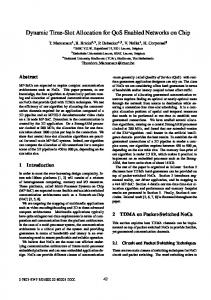
channel for communication) to share radio resources. Each platform equipped with a WNW radio constantly evaluates its bandwidth usage and reserves slots as needed. The reservation is based on slot usage (sending and receiving) information collected from its channelized neighbors. Consider the example shown in Figure 1. Assume that platform A is sending EF class traffic to platform C, platform B is sending BE class traffic to D, and platforms E and F are less than three hops away from each other. When traffic load increases, both E and F may attempt to reserve additional slots. However, the current USAP slot allocation scheme does not guarantee that E will have priority over other platforms. Therefore, F may secure available slots instead of E, leaving E short of slots and impacting those EF flows passing through E. Consequently, an application layer admission control function running at A will start downgrading impacted EF flows and/or rejecting new EF flows, whereas the BE traffic originating at B will remain unaffected. A
C G
E JTRS (Black) Network
F
I INTRODUCITON Network management has been used in daily operations for decades to maintain military networks. It is imperative to ensure that future military networks, such as those defined by the Future Combat System (FCS), Warfighter Information Network-Tactical (WIN-T), and Joint Tactical Radio System (JTRS) acquisition programs, will deliver the performance needed by modern command and control (C2) applications. Quality of Service (QoS) management is a focal point of network management research. It has been suggested that QoS management schemes at different layers of protocol stacks need to be coordinated in order to provide optimal QoS performance. A QoS performance issue arises in Wideband Networking Waveform (WNW) [1] from the layer 2 Unified Slot Allocation Protocol (USAP) [4] not sharing slot usage information on a per traffic class (i.e., DSCP marking [3]) basis. The USAP is a mechanism for platforms in a channelized neighborhood (i.e., using same frequency
978-1-4244-2677-5/08/$25.00 ©2008 IEEE
B
D
Figure 1. An Example of Sub-Optimal QoS Performance
Without modifying the USAP, our approach to the slot allocation problem is to have a Local QoS Control (LQC) component on each platform that regulates the USAP attempts to secure slots. The LQCs on platforms in a channelized neighborhood share their per traffic class radio resource needs. The sharing enables the LQC at each platform to determine the urgency of the platform’s need for slots compared to that of its channelized neighbors. Consequently, in platforms that have a less urgent need for slots, the LQC can filter local application traffic to reduce the demand for slots at the MI/MDL layer. As a result, platforms carrying higher priority traffic are more likely to fulfill their need for slots. The remainder of this paper is organized as follows. Section II describes the proposed LQC approach. Section III describes simulation results. Section 0 summarizes the main points of the paper and describes future work.
1 of 7
II PROPOSED CROSS-LAYER APPROACH: COORDINATED LOCAL QOS CONTROL (LQC) This section presents our proposed approach to the slot allocation issue. The approach is based on the assumption that the USAP slot allocation scheme remains unchanged. The proposed solution is dependent on having access to some black-side MI/MDL layer monitoring data on the red side of the network. It requires, for each radio interface of the platform:
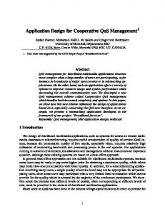
be more likely to fulfill their demand for slots via normal USAP operations. 3 slots/Frame EF: 2 slots/Frame BE: 1 slots/Frame 3 slots/Frame EF: 1 slots/Frame BE: 2 slots/Frame
II.A Approach Overview Our approach to the slot allocation problem is to have a Local QoS Control (LQC) component on each platform. The LQCs on platforms in a channelized neighborhood share their respective platform radio resource needs on a per traffic class basis. The sharing enables the LQC on each platform to prioritize its quest for slots. The LQC on each platform estimates per-class outgoing traffic load at regular intervals of time based on admission requests from local applications and monitoring data of forwarding traffic load from the black side. It then converts the outgoing traffic load to the corresponding number of data slots based on the mode (or the data rate) of the radio, and broadcasts per-class outgoing data slot usage information, along with the number of allocated slots, to LQCs at neighboring platforms.
3 slots/Frame EF: 4 slots/Frame BE: 0.5 slot/Frame
B
•
The per-class outgoing transit traffic rate, i.e., the forwarding traffic load; • The current mode (or the data rate) of the radio interface; and • The number of sending slots currently being allocated to the platform. The last two items together determine the current draining rate at each interface. We often use the terms “nodes” and “platforms” interchangeably; both terms refer to Ground, Airborne, and Soldier entities in FCS Network Communications Systems that are equipped with JTRS radios.
E
D
A
3 slots/Frame EF: 2 slots/Frame BE: 1 slot/Frame
C 3 slots/Frame EF: 2.1 slots/Frame BE: 1.5 slot/Frame
Figure 2. Example of LQC for USAP Slot Usage
In extreme cases, the LQC on a platform that is using all its allocated slots can voluntarily take preemptive action against some of its traffic flows to enable the MI/MDL layer to lend its allocated slots to neighbors. In the example shown in Figure 2, the EF traffic slot requirements are estimated to be smaller than the allocated slots at all platforms except A, which has an estimated 4 slots’ worth of EF traffic but only 3 allocated slots. The BE traffic, on the other hand, is mostly fully supported except at A and C. The USAP at the MDL layer will not activate the slot-loaning process in this situation since every platform is using all its allocated slots. If D slows down its BE traffic to 1 slot/Frame, it will be possible for A to borrow a slot from D. Accordingly, A will have 4 slots/Frame and D will have 2 slots/Frame. II.B LQC Functional Modules Figure 3 shows LQC functional modules as well as operational flows within a platform and between platforms. LQC
Neighborhood Traffic Measurement Exchange
Resource Usage Decision/Execution
Local Traffic Measurement Collection
Measurement Exchange
Periodically, the LQC on each platform determines if the platform has enough allocated slots to support its estimated outgoing traffic. In the case of a slot shortage, the LQC determines whether the local platform has a less urgent need for slots than its neighbors based on traffic load data received from other platforms. If the platform has a less urgent need, the LQC takes actions to reject or preempt (i.e., drop or delay) lower priority flows as it attempts to reduce its slot usage by reducing the traffic that it is introducing into the network. Note that in this scheme no control action is required if the platform has a more urgent need to transmit data than its neighbors. We envision that by having platforms with less urgent need back off from reserving more slots, the ones with more urgent needs will
LQC LTMC
LQC
NTME Application
RUD/E
Red IP
Cr
os sLa
Black IP
ye r
-A PI
MI MDL
Application
NTME
RUD/E
sos Cr
ye La
LTMC
PI Red IP r -A
Black IP
MI Local Traffic Measurement
Local Traffic Measurement
MDL
Figure 3. LQC Functional Modules and Operational Flows
The LQC component on each platform consists of the following functional modules: a local traffic measurement collection module, a neighborhood traffic measurement exchange module, and a resource usage decision/execution
2 of 7
module. The local traffic measurement collection module collects local traffic measurements and resource usage data. The neighborhood traffic measurement exchange module periodically shares local traffic measurements and resource usage data with other platforms in the same channelized neighborhood. The resource usage decision/execution module then evaluates resource usage needs among platforms in the neighborhood and performs appropriate actions such as rejecting new flows or preempting lower priority flows. II.B.1 Local Traffic Measurement Collection (LTMC) Module The LTMC module gathers local per-class traffic measurements and estimates periodically from the MDL layer in WNW. It also accesses the slot allocation information in terms of the interface draining rate and the number of slots being allocated to the platform. We assume that a cross-layer API for accessing these local measurement data is available. II.B.2 Neighborhood Traffic Measurement Exchange (NTME) Module The NTME module updates a per-class traffic load estimate report based on the measurement data it receives from the LTMC module. It broadcasts updated reports periodically to platforms in the neighborhood. The period between updates can be configured based on the characteristics of the network environment such as platform mobility and network density. The payload of a report message includes its sender, the sender’s per-class-traffic rates and the number of slots currently allocated to the platform. The report message is created by the LQC and passed down to the MI/MDL layer on the black side through UDP/IP layers on the red side, carried into a USAP broadcast channel, and finally delivered to 1-hop neighbors. II.B.3 Resource Usage Decision/Execution (RUD/E) Module Once the NTME module at a node N collects the traffic estimate and slot allocation reports from NTMEs at N’s neighboring nodes, the RUD/E module at node N decides its local QoS actions by executing the following actions: •
Determine the channelized neighborhood congestion status; • Calculate the packet dropping threshold, should the channelized neighborhood be determined to be congested; • Execute packet dropping according to the calculated threshold. Two methods of determining neighborhood congestion status are evaluated: Bandwidth-based Congestion Detection and Slot-based Congestion Detection. The two
differ in the way the Network Congestion Threshold (NCTH) is defined and evaluated against. 1) Bandwidth-based Congestion Detection In Bandwidth-based Congestion Detection, the NCTH of a channelized neighborhood is defined as a percentage of the neighborhood channel capacity. In other words, the NCTH in this case is an estimate of the maximum effective bandwidth for carrying data traffic after excluding overhead and common channel usage inefficiency. Node N then compares the estimated total traffic load in its channelized neighborhood against the NCTH, where the estimated total traffic load is calculated based on the traffic estimate reports collected from nodes in the neighborhood. If the estimated total traffic load is greater than the NCTH for its channelized neighborhood, node N proceeds with local QoS actions, i.e., potentially dropping packets, to help bring the future total traffic load below the NCTH. 2) Slot-based Congestion Detection In Slot-based Congestion Detection, the NCTH of a channelized neighborhood is defined as the number of slots to be shared by nodes in the neighborhood. To determine congestion status, node N first calculates for individual nodes in the neighborhood the number of slots required to carry their respective estimated traffic load. It then sums up all the required slots to see if the total number of slots required by all nodes in the neighborhood exceeds the number of available slots NCTH, and proceeds with local QoS actions accordingly. Once a channelized neighborhood is determined to be congested with either bandwidth-based or slot-based congestion detection, the goal of applying local QoS actions is for all nodes in the neighborhood to collectively bring the total traffic load down to a level below its network congestion threshold NCTH. To do so, every node first sets a target total traffic load for the network. It then decides the lowest priority traffic class that the nodes in the neighborhood can afford to carry without exceeding the targeted total traffic load. After the traffic class is identified, the RUD/E module drops all packets of priority lower than the identified traffic class. Depending on where the packet drop takes place, the RUD/E module can either drop locally generated traffic only at the Red IP layer or instruct the MI/MDL layer at the black side, if such APIs exist, to drop both locally generated and transit traffic. To quickly overcome potential congestion situations, a progressive scheme was used to set total traffic load targets. The more the Estimated Network Traffic Load (ENTL) is above NCTH, the less the Targeted Network Traffic Load (TNTL) becomes. In our simulations of the LQC functions, the TNTL is assigned as follows:
3 of 7
Margin = ENTL - NCTH If ( Margin < NCTH*0.1 )
TNTL = NCTH else if ( Margin > NCTH*0.1 && Margin < NCTH*0.3 ) TNTL = NCTH*0.9 else if ( Margin > NCTH*0.3 && Margin < NCTH*0.6 ) TNTL = NCTH*0.8 else TNTL = NCTH*0.3
Note that the decision regarding which traffic classes should be dropped is made independently by the RUD/E module at each node based on the per-class traffic load estimates collected from nodes in the same channelized neighborhood. It is possible that when some measurement exchange messages are lost, the basis for the decision will not be the same for all the nodes, and some nodes may decide to drop more traffic classes than others. Nevertheless, when nodes in a channelized neighborhood have the same set of per-class traffic load estimates, they will reach the same conclusion. III SIMULATION STUDIES In this section we report our analysis results based on simulation runs. We have experimented with several network configurations and traffic mixes. The results reported here are based on a representative network configuration and traffic mix. Section III.A describes the simulation setup, including the network and the traffic load simulated, the node model, and the schemes compared. Section III.B presents the performance metrics, followed by quantitative results in Section III.C. III.A Model and Simulation III.A.1 The Simulated Network Our study of the proposed approach is based on a 100node WNW network simulated using OpNet. The network consists of 8 WNW Local subnets, with 10 to 15 nodes in each subnet. In addition, there is a WNW Global subnet, with one node from each subnet as its member. All nodes in the simulated network support a WNW Local interface. Each node that is a member of the WNW Global subnet supports an additional WNW Global interface. The WNW Local interface channel capacity is roughly 1Mbps, and the WNW Global interface channel capacity is 5Mbps. Nodes in the simulated network are mobile, and the model updates MI routes every 10 minutes simulation time. Most packets take 3-7 hops to reach their destinations, including intra-subnet hopping from one channelized neighborhood to another channelized neighborhood, as well as intersubnet hopping through the WNW Global subnet. III.A.2 The Mapping of DSCP to MLPP Queues Figure 4 presents the mapping we used in our experiments when queuing packets at the MI/MDL layer MLPP queues. The numbers in parentheses are the DSCP values in Base 8. EF1 and EF2 are network control and user signaling traffic.
EF3 is short critical data traffic. EF4, EF5, EF8, EF9, and EF10 are voice traffic with MLPP levels of decreasing priorities (FO, F, I, P, and R respectively). EF6 consists of video, streaming, interactive, and file transfer traffic at the FO level, and EF7 consists of the same traffic types at the F level. To summarize the remaining classes, AF4 consists of video traffic, AF3 consists of streaming traffic, AF2 consists of interactive traffic, and AF1 consists of file transfer traffic. BE is Best Effort, the default traffic class. EF1 (60) EF2 (53) EF3 (57) EF4 (51) EF6 (41, 31, 21, 11)
EF5 (52) EF7 (42, 32, 22, 12)
EF8 (54) AF43 (44) AF33 (34) AF23 (24) AF13 (14)
EF9 (55) AF42 (45) AF32 (35) AF22 (25) AF12 (15)
EF10 (56) AF41 (46) AF31 (36) AF21 (26) AF11 (16) BE (00)
FO
F
I
P
R
Figure 4. The Mapping of PHB (DSCP) to MLPP Queues
III.A.3 Traffic Load We overloaded the simulated network to ensure triggering of various QoS schemes and to obtain sufficient data to differentiate their behaviors. At the same time, we attempted to create a traffic load that resembles the projected FCS traffic mix. Most of the simulation results reported here are based on a heavily loaded network that experienced close to 40% packet drops with the plain WNW scheme (i.e. with no Local QoS Control treatment). The traffic mix consists of 42% EF class traffic, 49% AF class traffic, and 9% BE traffic. The simulation time for each run is 1260 seconds, during which 2020 flows are generated at a rate of roughly 5 flows every 2 seconds. The first flow starts at 10 seconds into each simulation run. All flows have the same constant data rate of 2000 bytes per second. The duration of each flow differs based on its PHB class. The range of flow duration for EF class flows is between 20 and 90 seconds, for AF class flows is between 50 to 250 seconds, and for BE class flows is between 30 to 190 seconds. The generation of flows is as follows. To create a new flow, we first pick its source node from all nodes in the simulated network in a round-robin fashion. After that we pick its destination randomly from the rest of the nodes in the network. We then assign a traffic class to the flow randomly from 14 PHB classes, EF1-EF9, AF4, AF3, AF2 AF1, and BE, and finally select its duration randomly with a uniform distribution from the respective range of its assigned traffic class. The AF classes are in fact AF43, AF33, AF23, and AF13; thus, according to the PHB to MLPP mapping, the AF class traffic shares the same MLPP I queue as the EF8 traffic. With 5 flows being generated every 2 seconds, in our simulated 100 node network a new flow is generated for each node every 40 seconds. During each simulation run a
4 of 7
node can have up to 7 simultaneous flows or 112 kbps locally generated traffic. With the WNW parameter values simulated, a node needs at least 9 slots per frame to carry just 112 kbps incoming traffic, without accounting for the additional slots needed for forwarding transit traffic. III.A.4 QoS Approaches Studied We report simulation results of four different approaches: WNW, B_LQoS, S_LQoS and M_LQoS. WNW is our baseline case, representing existing JTRS implementation (MLPP at layer 2) with no added mechanisms. B_LQoS and S_LQoS implement our proposed LQC functions with bandwidth-based and slot-based congestion detection respectively. M_LQoS emulates the case that modifies MI/MDL slot allocation to be class-aware, and uses LQC functions that coordinate their knowledge of slot allocation III.B QoS Evaluation We define a plausible QoS metric here to assess whether, and by how much, our techniques improve QoS. This metric is computed based on the results of simulation runs, although it could also be used to evaluate the performance of a functioning FCS MANET network if that network were instrumented to gather and report the relevant performance indicators to its network management system. Similar to the utility function defined in [2], we measure QoS using a flow-based approach, which can be defined loosely as measuring the aggregate fraction of flows that “satisfy” their QoS objective. More precisely, the QoS measure U Ti for a nonempty set of offered flows of priority class i over an observation period T is U Ti = ∑ s (i, j , T ) / N T i ,
(1)
j
where NT i
denotes the total number of offered
flows of class i (admitted or rejected) over the observation period T, and s (i, j, T ) denotes the QoS satisfaction score (measure) for flow j of class i over the observation period T. We often use U i , N i and s (i, j ) , instead of U Ti , N T i and
By convention, we set U Ti = 1 if there are no offered flows in priority class i over the observation period T. Note that 0 ≤ U Ti ≤ 1 . For flow satisfaction based on multiple performance parameters, we take the product of the sequence of satisfaction functions for each parameter as the overall flow satisfaction. That is, if sk (i, j ) represents the flow satisfaction function for flow j of class i with respect to parameter k, then the overall flow satisfaction for flow j of class i is s (i, j ) = ∏ s k (i, j ) .
Assuming that the priority classes are numbered so that the lowest-numbered classes have the highest priority, we then define the overall QoS measurement function as U = ∑α −iU i / ∑α −i , i
(3)
i
where α > 1 is the weight. In other words, we weight the class QoS values exponentially, with the highest priority classes getting highest weight. This expression is a heuristic reflecting the fact that satisfaction for the highest priority (most important) classes should count the most in attaining a high value of U. Note that 0 ≤ U ≤ 1 . We analyze our simulation results using three different weights, α = 1.2 , α = 1.5 , and α = 2 . In this study, the satisfaction of each flow is the product of its satisfaction scores on two QoS parameter: packet loss ratio and average latency. Table 1 gives a set of thresholds we use for flow satisfaction calculations based solely on PHB class, where the latency thresholds are averages over the entire duration of the flow. The two values, thresh0 and thresh1, are lower and upper threshold bounds of a region of performance space. The flow satisfaction takes on intermediate score between 1 and 0 by linear interpolation in this region. Table 1. Flow Satisfaction Thresholds
EF1 EF2 EF3 EF4 EF5 EF6 EF7 EF8 EF9 EF10 AF4 AF3 AF2 AF1 BE
s (i, j , T ) , when the context of the observation period T is
clear, for example, when T represents the entire duration of a simulation run. We require s (i, j ) = 1 if all QoS objectives for flow j are met, while s (i, j ) = 0 if the QoS treatment of flow j is considered completely unsatisfactory. The latter normally includes the case when the flow was blocked. The function s (i, j ) might equal something between zero and one if a concept of partial flow satisfaction is allowed.
(2)
k
packet loss ratio thresh0 0.001 0.001 0.0015 0.01 0.02 0.03 0.03 0.03 0.03 0.05 0.2 0.2 0.2 0.2 0.4
packet loss ratio thresh1 0.01 0.01 0.015 0.04 0.045 0.05 0.05 0.05 0.05 0.07 0.3 0.3 0.3 0.3 0.6
latency (sec) thresh0 0.5 0.5 0.5 0.5 0.9 1.0 1.0 1.0 1.0 1.5 5.0 5.0 5.0 5.0 10
latency (sec) thresh1 1.9 1.9 1.9 1.9 2.4 3.0 3.0 3.0 3.0 4.0 10.0 10.0 10.0 10.0 20
III.C Simulation Results This section presents our analysis of simulation results.
5 of 7
III.C.1.1 Egress Byte Count By offering the same ingress traffic load to a network that is configured to simulate different QoS control mechanisms, the Egress Byte Count is a good performance indicator for comparison of various QoS mechanisms. Figure 5 depicts the overall network Egress Byte Count of various LQC schemes per PHB classes, and Figure 6 the total network Egress Byte Count. In both figures, Ingress is the total traffic load (in Byte Count) generated at the source, and WNW is the Egress Byte Count of the plain WNW scheme, which serves as a baseline for comparison. Egress Byte Count LQC Schemes 50000000 45000000 40000000
Byte Count
35000000
WNW
30000000
B_LQoS
25000000
S_LQoS
20000000
M_LQoS
On a per PHB class basis, Figure 5 indicates that the LQC schemes are able to match (and actually perform slightly better than) the near perfect delivery of the EF1-EF7 class traffic by the WNW scheme, and improve significantly on the delivery of EF8, EF9 and AF4 class traffic. On the EF8 class traffic, the delivery ratio goes up from 45% (WNW) to 96% (B_LQoS). On the EF9 class traffic, it goes up from 25% to 47%, and on the AF4 class traffic, from 42% to 53%. The two IP Layer LQC schemes, B_LQoS and S_LQoS, suffer slightly in the delivery of AF1 and BE class traffic, whereas the M_LQoS scheme results in big drops in the delivery of AF3, AF2, and AF1 class traffic due to its drops of transit low priority traffic. III.C.1.2 Average Latency
Ingress
15000000
it drops transit low priority PHB class packets at the MI/MDL Layer, the network has wasted shared resources to carry those packets for a few hops.
10000000
Average Latency by PHB Classes LQC Schemes
5000000 0 EF1
EF2
EF3:
EF4:
EF5:
EF6:
EF7:
EF8:
EF9:
AF4
AF3
AF2
AF1
40
BE
PHB Class Average Latency in Seconds
35
Figure 5. Comparison of Various LQC Schemes (Egress Byte Count) Total Egress Byte Count LQC Schemes
30 25
WNW B_LQoS
20
S_LQoS M_LQoS
15 10 5
M_LQoS
0 EF1
EF2
EF3:
EF4:
EF5:
EF6:
EF7:
EF8:
EF9:
AF4
AF3
AF2
AF1
BE
PHB Class
S_LQoS
Figure 7. Comparison of Various LQC Schemes (per PHB Class Average Latency)
B_LQoS
WNW
Ingress
0
50000000
100000000
150000000
200000000
250000000
300000000
350000000
400000000
Byte Count
Figure 6. Comparison of Various LQC Schemes (Total Egress Byte Count)
Of the three LQC schemes that we simulated, B_LQoS and S_LQoS differ only in the way they determine the congestion status. Since S_LQoS tracks the actual number of slots available for sharing in each channelized neighborhood, by comparing the Egress Byte Count of B_LQoS to that of S_LQoS we get a sense of how well the Network Congestion Threshold we set for B_LQoS reflects the actual congestion situation. As shown in Figure 6, the total number of bytes delivered went up from the WNW scheme (61.3%) to the B_LQoS scheme (64.7%) to the highest with the S_LQoS scheme (65.7%). In a heavily loaded network, being able to push through an additional 4% of traffic is significant. It also shows that the B_LQoS scheme is slightly more aggressive than the S_LQoS scheme in detecting and reacting to congestion. On the other hand, the M_LQoS scheme (58.5%) performs less well with respect to total Egress Byte Count, because when
Figure 7 compares the average latency performance of various LQC schemes against the plain WNW scheme. The metric is an average over the latency of the packets that have been delivered successfully. All LQC schemes improve substantially the average latency performance of EF5 and EF7 class traffic. They also substantially improve the average latency of AF class traffic because they drop AF class packets from congested neighborhoods at the source instead of letting some of them fight their way through the network and get dropped along the way. On the other hand, LQC schemes managed to deliver more EF8 and EF9 class traffic, as we mentioned in Section III.C.1.1. The EF8 class traffic exhibits an average latency that reflects the average latency of the MLPP I queue in a heavily loaded network, which is around 10 seconds. The average latency of the EF9 class traffic becomes longer, however, because the EF9 class traffic occupies the MLPP P queue alone; when more EF9 class packets pass through the queue successfully, their average latency gets longer. III.C.1.3 Overall Satisfaction Figure 8 presents the performance results of various LQC schemes based on a combined score of packet loss ratio
6 of 7
and average latency, as defined in Section III.B. The LQC schemes consistently exhibit noticeable improvement over the plain WNW scheme on the satisfaction score of high priority PHB classes, mostly due to shorter average latency. The improvement can be as high as 16% (from 56% satisfaction to 72% on EF5). For the low priority PHB classes, most LQC schemes still maintain or exceed the level of satisfaction seen in the plain WNW scheme. One exception is the M_LQoS scheme, whose AF3, AF2, and AF1 satisfaction scores suffer due to significant dropping of transit traffic packets in those classes. Satisfaction Score by PHB Classes LQC Schemes 1.2 1
Satisfaction
0.8 WNW B_LQoS
0.6
S_LQoS M_LQoS
0.4 0.2 0 EF1
EF2
EF3:
EF4:
EF5:
EF6:
EF7:
EF8:
EF9:
AF4
AF3
AF2
AF1
BE
PHB Class
Figure 8. Comparison of LQC Schemes (per PHB Class Satisfaction)
Figure 9 compares the overall satisfaction score of the LQC schemes with the WNW scheme. As defined in Section III.B, the overall satisfaction score is an exponentially weighted average of per PHB class QoS value over all PHB classes. The figure presents the scores using three different weights (i.e. with three different values for the weighting factor α); the larger the weight, the more we factor the higher priority PHB class QoS value. In all three weights, the LQC schemes show 2-6% satisfaction improvement. Overall Satisfaction Score LQC Schemes 0.8 0.7
Satisfaction
0.6 0.5
WNW B_LQoS
0.4
S_LQoS M_LQoS
0.3
functions at the IP layer. The combined monitoring data collected from platforms in a neighborhood enables the QoS control functions on each platform to make intelligent local decisions about sharing radio resources. We also presented the evaluation of our proposed approach based on a simulation model and a plausible QoS metric. When applied with a properly configured Network Congestion Threshold, the Local QoS Control (LQC) scheme can have double-digit QoS value increase over that of the plain WNW scheme. It can also overcome MLPP queuing dominance in some traffic classes (e.g., 16% satisfaction improvement for EF5 class traffic, or double the delivery of EF8 and EF9 class traffic). The approach of preempting local low priority application traffic may have a somewhat limited effect on addressing the sub-optimal slot allocation issue. Take for instance a platform A with two slots’ worth of EF traffic coming from local applications, another two slots’ worth of transit BE traffic, and three allocated slots. The LQC may conclude that the platform should not attempt to reserve one additional slot. However, it cannot apply the preemptive technique here, as local application traffic is of higher priority. A preferred approach is for the LQC to be able to instruct USAP at the MI/MDL layer not to reserve additional slots. To do so, however, the MI/MDL layer needs to provide a management interface to the LQC for issuing such control requests. The LQC approach also incurs additional data traffic overhead for exchanging per-class traffic load information. For nodes to exchange data every 3 seconds in a 10 node channelized neighborhood, we estimate the overhead is roughly 2 bps, or 0.2% of the bandwidth for each 1 Mbps frequency channel. We recognize that USAP shares slot usage information through bootstrap slots, except that the information is not on a per traffic class basis. If we could make changes to USAP to share slot usage breakdown by traffic class, we could not only avoid duplicating the neighborhood information-sharing mechanism at the IP layer, but also exchange information through control slots instead of data slots, thus minimizing data traffic overhead.
0.2
REFERENCES
0.1 0 1.2
1.5
[1]
2
Weight
Figure 9. Overall Satisfaction of LQC Schemes in Various Weight Values
[2]
IV CONCLUDING REMARKS We have described the impacts of the WNW Layer 2 implementation on QoS performance, and presented our proposed approach for improving the effectiveness of FCS QoS solutions. We assume that per-class traffic monitoring data at the MI/MDL layer is available to the QoS control
[3] [4]
7 of 7
The Boeing Company, “Wideband Networking Waveform (WNW) for the Joint Tactical Radio System (JTRS) Cluster 1”, October 2004. Chiang, C. et al., “On Automated Policy Generation for Mobile Ad Hoc Networks” in Proc. of IEEE POLICY 2007, Bologna, Italy. RFC 2474, “Definition of the Differentiated Services Field (DS Field) in the IPv4 and IPv6 Headers”, December 1998. Young, C.D., “USAP multiple access: Dynamic resource allocation for mobile multihop multichannel wireless networking”, in Proc. of MILCOM 1999.