fast multilevel routing considering crosstalk and performance optimization. To handle the crosstalk minimization problem, we incorporate an intermediate stage of layer/track assignment ... D.-T. Lee is with the Department of Computer Science and Information En- ...... Tsung-Yi Ho received the M.S. degree in computer.
IEEE TRANSACTIONS ON COMPUTER-AIDED DESIGN OF INTEGRATED CIRCUITS AND SYSTEMS, VOL. 24, NO. 6, JUNE 2005
869
Crosstalk- and Performance-Driven Multilevel Full-Chip Routing Tsung-Yi Ho, Yao-Wen Chang, Member, IEEE, Sao-Jie Chen, Senior Member, IEEE, and Der-Tsai Lee, Fellow, IEEE
Abstract—In this paper, we propose a novel framework for fast multilevel routing considering crosstalk and performance optimization. To handle the crosstalk minimization problem, we incorporate an intermediate stage of layer/track assignment into the multilevel routing framework. For performance-driven routing, we propose a novel minimum-radius minimum-cost spanning tree heuristic for global routing. Compared with the state-of-the-art multilevel routing with the routability mode, the experimental results show that our router achieved a 6.7X runtime speedup, reduced the respective maximum and average crosstalk (coupling length) by about 30% and 24%, reduced the respective maximum and average delay by about 15% and 5%. Compared with the timing-driven mode, the experimental results show that our router still achieved a 5.9X runtime speedup, reduced the respective maximum and average crosstalk by about 35% and 23%, reduced the respective maximum and average delay by about 7% and 10% in comparable routability, and resulted in fewer failed nets. Index Terms—Detailed routing, global routing, layout, noise optimization, physical design, routing, timing optimization.
I. INTRODUCTION
W
ITH decreasing feature sizes, higher clock rates, and increasing interconnect densities, crosstalk has become a major concern of comparable importance to area and timing in IC design. Crosstalk profoundly affects the circuit performance in very deep submicron (VDSM) technology; it is introduced by a coupling between two neighboring wires. For example, two adjacent wires form a coupling capacitor. A voltage or a current change on one wire can thus interfere the signal
Manuscript received October 25, 2003; revised March 12, 2004. The work of Y.-W. Chang was supported in part by the National Science Council of Taiwan under Grant NSC-92-2215-E-002-018 and in part by Grant NSC-93-2752-E002-008-PAE. The work of S.-J. Chen was supported in part by the National Science Council of Taiwan under Grant NSC 91-2215-E-002-042. The work of D. T. Lee was supported in part by the National Science Council under Grant NSC-92-2213-E-001-024, in part by Grant NSC-92-3112-B-001-018-Y, in part by Grant NSC-92-3112-B-001-0, in part by Grant NSC-93-2422-H-001-0001, and in part by Grant NSC-93-2752-E-002-005-PAE. A preliminary version of this paper was presented at the International Conference on Computer-Aided Design, San Jose, CA, 2003 . This paper was recommended by Associate Editor M. D. F. Wong. T.-Y. Ho is with the Department of Electrical Engineering, National Taiwan University, Taipei 106, Taiwan. Y.-W. Chang is with the Graduate Institute of Electronics Engineering and the Department of Electrical Engineering, National Taiwan University, Taipei 106, Taiwan. S.-J. Chen was with the IBM T. J. Watson Research Center, Yorktown Heights, NY 10598 USA. He is now with the Graduate Institute of Electronics Engineering and the Department of Electrical Engineering, National Taiwan University, Taipei 106, Taiwan. D.-T. Lee is with the Department of Computer Science and Information Engineering, National Taiwan University, Taipei 106, Taiwan, and the Institute of Information Science, Academia Sinica, 115 Taipei, Taiwan. Digital Object Identifier 10.1109/TCAD.2005.847902
on the other wire. Crosstalk is an unwanted variation which makes the behavior of a manufactured circuit deviate from the expected response. The deleterious influences of crosstalk can be classified into two categories. One is malfunctioning, which makes the logic values of circuit nodes differ from what we desire; the other is timing change, which is caused by switching behavior. Therefore, in addition to routability and timing performance, crosstalk minimization should also be considered in VDSM router design. Traditionally, the complex routing problem is often solved by using the two-stage approach of global routing, followed by detailed routing. Global routing first partitions the routing area into tiles and decides tile-to-tile paths for all nets while detailed routing assigns actual tracks and vias for nets. Many routing algorithms adopt a flat framework of finding paths for all nets. Those algorithms can be classified into sequential and concurrent approaches. Early sequential routing algorithms include maze-searching approaches [22] and line-searching approaches [16], which route net-by-net. Most concurrent algorithms apply network-flow [1] or linear-assignment formulation [6], [27] to route a set of nets at one time. The major problem of the flat framework lies in its scalability for handling larger designs. As technology advances, technology nodes are getting smaller and circuit sizes are getting larger. To cope with the increasing complexity, researchers proposed to use hierarchical approaches to handle the problem. Marek-Sadowska [27] proposed a hierarchical global router based on linear assignment. Chang et al. [6] applied linear assignment to develop a hierarchical, concurrent global and detailed router for field programmable gate arrays (FPGAs). The two-level, hierarchical routing framework, however, is still limited in handling the dramatically growing complexity in current and future IC designs. As pointed out in [8], for a 0.07m process technology, a 2.5 2.5 cm chip may contain over 360 000 horizontal and vertical routing tracks. To handle such high design complexity, the two-level, hierarchical approach becomes insufficient. Therefore, it is desired to employ more levels of routing for very large-scale IC designs. The multilevel framework has attracted much attention in the literature recently. It employs a two-stage technique: coarsening followed by uncoarsening. The coarsening stage iteratively groups a set of circuit components (e.g., circuit nodes, cells, modules, routing tiles, etc.) based on a predefined cost metric until the number of components being considered is smaller than a threshold. Then, the uncoarsening stage iteratively ungroups a set of previously clustered circuit components and refines the solution by using a combinatorial optimization technique (e.g., simulated annealing, local refinement, etc).
0278-0070/$20.00 © 2005 IEEE
870
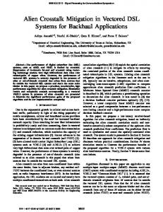
Fig. 1.
IEEE TRANSACTIONS ON COMPUTER-AIDED DESIGN OF INTEGRATED CIRCUITS AND SYSTEMS, VOL. 24, NO. 6, JUNE 2005
Multilevel framework flow.
The multilevel framework has been successfully applied to VLSI physical design. For example, the famous multilevel partitioners, ML [2], and hMETIS [19], the multilevel placer, mPL [4], and the multilevel floorplanner/placer, MB*-tree [23], all show the promise of the multilevel framework for large-scale circuit partitioning, placement, and floorplanning. A framework similar to multilevel routing was presented in [15], [25], and [26]. Lin et al. in [25] and Hayashi and Tsukiyama in [15] presented hybrid hierarchical global routers for multilayer very large scale integrations (VLSIs) [15], in which both bottom-up (coarsening) and top-down (uncoarsening) techniques were used for global routing. Marek-Sadowska [26] proposed a global router based on the outermost loop approach. The approach is similar to the coarsening stage of multilevel routing. Recently, Cong et al. proposed a pioneering multilevel global-routing approach for large-scale, full-chip, routability-driven routing [8]. Cong et al. later proposed an enhanced multilevel routing system named MARS [9], which incorporates resource reservation, a graph-based Steiner tree heuristic and a history-based multi-iteration scheme to improve the quality of the multilevel routing algorithm in [8]. The final results of both of the multilevel algorithms are tile-to-tile paths for all the nets. The results are then fed into a detailed router to find the exact connection for each net. Lin and Chang also proposed a multilevel approach for full-chip routing, which considers both routability and performance [5], [24]. This framework integrates global routing, detailed routing, and resource estimation together at each level, leading to more accurate routing resource estimation during coarsening and thus facilitating the solution refinement during uncoarsening. Their experimental results show the best routability among the previous works.
TABLE I FRAMEWORK COMPARISON BETWEEN [8] AND [24] AND OURS
Different from the aforementioned works, ours has the following distinguished features. A new framework of performing congestion-driven 1) global routing at the coarsening stage, followed by an intermediate stage of routing layer/track assignment for crosstalk optimization, and then detailed routing at the uncoarsening stage. By performing detailed routing after layer/track assignment, we can preserve more flexibility for allocating nets for crosstalk optimization. A novel minimum-radius minimum-cost spanning-tree 2) (MRMCST) heuristic is adopted [28] to construct routing trees for performance optimization. An efficient and effective layer/track assignment 3) scheme is incorporated for crosstalk and runtime optimization. Fig. 1 shows our multilevel framework, and Table I summarizes the differences of the framework among [8], [24] and ours. Given a netlist, we first run the MRMCST algorithm to construct the topology for each net, and then decompose each net
HO et al.: CROSSTALK- AND PERFORMANCE-DRIVEN MULTILEVEL FULL-CHIP ROUTING
Fig. 2.
Routing graph. (a) Partitioned layout. (b) Routing graph.
into 2-pin connections, with each connection corresponding to an edge of the MRMCST. Our multilevel framework starts with coarsening of the finest tiles of level 0. At each level, pattern routing is used for routability-driven global routing. After the coarsening stage, we perform a crosstalk-driven layer/track assignment for crosstalk optimization. At the uncoarsening stage, we perform detailed routing. Further, the unroutable nets are handled by point-to-path maze routing [5], [9], [24] and rip-up and reroute to refine the routing solution level by level. Comparing the routability mode of our router with [5] and [24], the experimental results show that our router, achieved a 6.7X runtime speedup, reduced the respective maximum and average crosstalk (coupling length) by about 30% and 24%, reduced the respective maximum and average delay by about 15% and 5%. Compared with the timing mode of our router, the experimental results show that our router still achieved a 5.9X runtime speedup, reduced the respective maximum and average crosstalk by about 35% and 23%, reduced the respective maximum and average delay by about 7% and 10% in comparable routability, and resulted in fewer failed nets. The results show the promise of our approach. The rest of this paper is organized as follows. Section II presents the routing model and the multilevel routing framework. Section III presents our novel framework for run-time and crosstalk optimization. Experimental results are shown in Section IV. Finally, we give concluding remarks in Section V. II. PRELIMINARIES A. Routing Model Our global routing algorithm is based on a graph search technique guided by the congestion information associated with routing regions and topologies. The router assigns higher costs to route nets through congested areas (or those of higher delay and/or crosstalk costs) to balance the net distribution among routing regions. Before we can apply the graph search technique to multilevel routing, we first need to model the routing resource as a graph such that the graph topology can represent the chip structure. Fig. 2 illustrates the graph modeling. For the modeling, we first partition a chip into an array of rectangular subregions. These subregions are called global cells (GCs). A node in the graph represents a GC in the chip, and an edge denotes the boundary between two adjacent GCs. Each edge is assigned a capacity according to the physical area or the number of tracks of a GC. The graph is used to represent the routing area and is called a
871
, where is the level multilevel routing graph, denoted by number. A global router finds GC-to-GC paths for all nets on a routing graph to guide the detailed routing. The goal of global routing is to route as many nets as possible while meeting the capacity constraint of each edge and any other constraint, if specified. As the process technology advances, multiple routing layers are possible. The number of layers in a modern chip can be more than six [13]. Wires in each layer run either horizontally or vertically. We refer to the layer as a horizontal (H) or a vertical (V) routing layer. B. Multilevel Routing Model corresponds to the routing graph As illustrated in Fig. 1, of level 0 of the multilevel coarsening stage. At each level, our global router first finds routing paths for the local nets (or local 2-pin connections) (those nets [connections] that entirely sit inside a GC). After the global routing is performed, we merge into a larger GC and at the same time perform 2 2 GC’s of resource estimation for use at the next level (i.e., level 1 here). Coarsening continues until the number of GCs at a level, say the th level, is below a threshold. After the coarsening is finished, a crosstalk-driven layer/track assignment is performed to assign long and straight segments to underlying routing resources. The uncoarsening stage tries to refine the routing solution of the unassigned segments of the level . During uncoarsening, the unroutable nets are performed by point-to-path maze routing and rip-up and reroute to refine the routing solution. Then we proceed ) of uncoarsening by expanding each to the next level (level to four finer . The process continues until we reach level 0 when the final routing solution is obtained. III. MULTILEVEL ROUTING FRAMEWORK Our multilevel routing algorithm is inspired by the work of [5] and [24]. Nevertheless, different from the framework of [5] and [24] that integrates global routing, detailed routing, and resource estimation together at each level, our framework performs global routing in the coarsening stage, followed by layer/track assignment in an intermediate stage, and then detailed routing in the uncoarsening stage. At the coarsening stage, a fast congestion-driven pattern routing [20] is used for global routing level by level. After the coarsening stage, we perform layer/track assignment for crosstalk optimization. At this intermediate stage, long and straight segments tend to be assigned to specified layers/tracks, leading to more efficient detailed routing in the uncoarsening stage since often only short segments need to be handled during detailed routing. At the uncoarsening stage, the unroutable nets are routed by point-to-path maze routing and by rip-up and reroute to refine the routing solution level by level. A. Performance-Driven Routing Tree Construction In VDSM IC designs, interconnection delay dominates the performance of a circuit. Therefore, improving the wire delay also improves the overall chip performance. Many techniques have been developed to facilitate high-performance IC designs. For example, the algorithms for constructing performance-driven routing trees have received much attention
872
IEEE TRANSACTIONS ON COMPUTER-AIDED DESIGN OF INTEGRATED CIRCUITS AND SYSTEMS, VOL. 24, NO. 6, JUNE 2005
[11]. The minimum spanning tree (MST) topology leads to the minimum total wire length, where congestion is often easier to be controlled than in other topologies. However, its topology may result in longer critical paths and degrade circuit performance. In contrast, a shortest path tree (SPT) may result in the best performance, but its total wire length (and congestion) may be significantly larger than that constructed by the MST algorithm. In [11], researchers used the idea of incrementally modifying an MST to construct a performance-driven routing tree for a smooth tradeoff between the tree radius (maximum signal delay) and the tree cost (total interconnection length). On one hand, minimizing wire length minimizes driver’s output resistance and the total wire capacitance. On the other hand, minimizing the path length from the source to a sink also minimizes loading capacitance. Thus, both wire length and path length minimization are comparably important for RC delay minimization. Different from the work presented in [11], our algorithm tries to find a timing-driven routing tree. We make use of the MRMCST, i.e., a minimum-cost spanning tree with a minimum radius. Since finding the MRMCST is NP-hard [28], we resort to a heuristic to obtain efficient solutions. Given a vertex in a graph , its eccentricity, denoted by , is the distance from to the farthest vertex in , which is also referred to as the radius of with respect to . The diameter of a graph is the longest path between any two vertices in the graph. The pseudocenter (pc) of a graph , denoted by , is a point on an edge or a vertex of such that the distances from pc to the farthest vertices of are the same. It is known that the pc must belong to the diameter of a is the radius of [17]. Note that given an graph, and edge-weighted graph , its minimum-cost spanning tree (MST) in general is not unique. The essential edges are those edges that must be included in every MST of , and the optional edges are those that may be included in an MST of . We shall modify the edge-coloring process of introduced by Tarjan [30] to color the essential edges blue, the optional edges green, and the non-MST edges red. disjoint components, each conInitially there are taining a vertex of . As edges are colored green or blue, disjoint components containing the end vertices of newly colored (green or blue) edges are merged together to form a new component. When the number of components becomes one, the algorithm will terminate and the remaining uncolored edges are colored red. The set of blue (or essential) edges must belong to every MST and the set of green (or optional) edges may belong to an MST. The former is referred to as the intersection graph of all the MSTs, denoted MSTIG, and the single component that remains in the above edge-coloring algorithm is referred to as the union graph of all the MSTs, denoted MSTUG [28]. The edge-coloring algorithm is summarized in Fig. 3. It can be shown that time, the MSTUG and MSTIG can be constructed in where is the number of vertices. See Fig. 4(b) for an example of MSTUG and MSTIG construction. Note that the MSTIG consists solely of blue edges, and it may contain a forest of more than one tree, and these blue trees are interconnected by green or optional edges to form the MSTUG.
Fig. 3. Algorithm for constructing an MSTUG and an MSTIG.
The MRMCST is then obtained by selecting the optional edges in an optimal manner to connect the blue trees. Since the problem of finding the MRMCST is NP-hard [28], heuristics are proposed to obtain suboptimal solutions. It is the strategy by which the optional edges are selected that determines the quality of the suboptimal MRMCST. A greedy method, called locally optimal connection strategy (LOCS) was introduced in [28]. As elaborated below, we have implemented it with some modifications and incorporated it into our multilevel framework. Let the blue tree containing the source be denoted . If there exist more than one optional edge incident to a vertex in , we break the tie by choosing the edge , where , and that minimizes is defined as
where denotes the pseudocenter of is the is the length of edge . The distance from to , and cost to form a new super blue blue tree is then merged with tree , and the process repeats until we obtain a suboptimal MRMCST. The sub-MRMCST algorithm that employs LOCS is summarized in Fig. 5. Fig. 4(c) shows the suboptimal MRMCST obtained from the graph shown in Fig. 4(b). Theorem 1: The sub-MRMCST heuristic runs in time, where is the number of veris the number of optional edges. tices and when the Proof: The merging (connecting) cost is blue tree is connected to the super blue tree. . Since every opHence, the total connecting cost will be tional edge is inserted into the priority queue exactly once and each insertion/deletion for the priority queue needs
HO et al.: CROSSTALK- AND PERFORMANCE-DRIVEN MULTILEVEL FULL-CHIP ROUTING
873
Fig. 4. Example MRMCST construction. (a) The given vertex set. (b) The MSTUG contains all edges and the MSTIG contains all solid edges. (c) The resulting MRMCST.
After a suboptimal MRMCST is constructed, timing analysis based on the Elmore delay model is performed from the tree source to all sinks. If a target node violates the timing constraint, we modify the tree topology by deleting this local connection and then tracing back from the target node to the tree source to find a new parent for the connection that can meet the timing constraint. (Although this process might increase the total wirelength and thus the total wire capacitance, the decrease of the path delay due to lower source-to-sink loading capacitance is even more significant.) After all nets meet the timing constraint, we start to route them in the coarsening stage. B. Crosstalk-Driven Layer/Track Assignment
Fig. 5. Heuristic for constructing a suboptimal MRMCST.
time, the total time complexity for MRMCST construction is , where is the number of vertices and is the number of optional edges.
As fabrication technology shrinks into the VDSM era, on-chip minimum feature sizes continue to decrease, and devices and interconnection wires are placed in closer proximity in order to reduce interconnection delay and routing area. The increasing of aspect ratio of wires and the decreasing of interconnect spacing have made the coupling capacitance larger than self capacitance. In fact, the ratio of coupling capacitance is reported to be even as high as 70%–80% of the total wiring capacitance, even in 0.25- m technology. Crosstalk is mostly caused by coupling capacitance between interconnection wires. In general, the crosstalk between two wires is proportional to their coupling capacitance, which is determined by the relative positions of the wires. The coupling capacitance between a pair of parallel wires is proportional to their coupling length, and is inversely proportional to their separating distance. The coupling capacitance between a part of orthogonal wires is negligible in comparison with the coupling capacitance between a pair of parallel wires in current technology. Consequently, it is reasonable to assume that there is crosstalk only between adjacent parallel wires. Recently, there has been much research on the coupling problem in both global and detailed routing. Zhou and Wong [31] minimized crosstalk at the global routing stage. Chaudhary et al. [7] proposed wire spacing after detailed routing to reduce
874
IEEE TRANSACTIONS ON COMPUTER-AIDED DESIGN OF INTEGRATED CIRCUITS AND SYSTEMS, VOL. 24, NO. 6, JUNE 2005
Fig. 6. Constraint graph modeling for track assignment. (a) The subHCG for the given instance. (b) The corresponding bipartite assignment graph. (c) The combination graph.
crosstalk. This technique can be applied as a postprocessing and used for improving an existing layout, but it is not suitable for routing. However, both global routing and detailed routing are not the best stage to address crosstalk. It might be too early to handle crosstalk during global routing since the relative positions and ordering of nets are not determined at this stage; therefore, the best that one can possibly do is to use rough statistical estimators that discourage nets from entering regions where unwanted proximities seem likely. Conversely, it is too late for detailed routing since area routers that embed one net at a time may encounter unsolvable rip-up/reroute problems when trying to embed a late-routing net that must traverse a region already dense with conflicting aggressor or victim nets. To address these problems, Kay and Rutenbar [21] suggested an integer linear programming (ILP)-based track/layer assignment method to do crosstalk optimization. However, the ILPbased approach is very time-consuming and thus not suitable for large and complex design. Batterywala et al. [3] proposed a fasttrack assignment heuristic considering routability, but crosstalk was not addressed in the work. Inspired by the work of [3], we propose a fast layer/track assignment heuristic for crosstalk optimization. After the coarsening stage, we may obtain several long horizontal and vertical segments. To simplify the layer/track assignment problem, we only assign segments which span more than one complete global cell in a row or a column. (We handle short segments during detailed routing.) The layer/track assigner works on a full row or column of the global cell array at a time. Each row (column) is called a panel. for We first build the horizontal constraint graph corresponds to all segments in the panel. Each vertex a segment in the panel. Two vertices and are connected iff these segments belong to two different by an edge nets and their spans overlap. The edge cost of represents the coupling length if and are assigned to
adjacent tracks. We define the crosstalk-driven layer assignment problem as follows. The Crosstalk-Driven Layer Assignment (CLA) Problem: Given a set of layers and a set of segments , find an assignment of segments to the layers that minimizes the sum of the coupling costs (lengths) of all nets in all layers. Here, the cost for CLA comes from the overlapping lengths of nets since nets are not yet assigned to tracks during the layer assignment and all information we have is the spans of nets. The CLA problem can be formulated as the max-cut, -coloring (MC) problem [29]. However, the MC problem is NP-complete [29]. Thus, we resort to a simple yet efficient heuristic by constructing a maximum spanning tree from the given HCG. Since a tree can be colored in linear time if we have layers, we shall first partition the vertices incident on edges with larger costs (coupling lengths) and allocate the corresponding segments to different layers. Let be the set of tracks inside a panel. Each track can be represented by its set of constituent contiguous intervals. . Each is: 1) Denoting these intervals by , we have a blocked interval, where no segment from can be assigned; 2) an occupied interval, where a segment from has been assigned; 3) or a free interval, where no segment from the set has yet been assigned. is said to be assignable to A segment , iff implies that either is a free interval or is an interval occupied by a segment of the same net. Thus, the crosstalk-driven track assignment problem can be defined as follows. The Crosstalk-Driven Track Assignment (CTA) Problem: Given a set of tracks and a set of segments , find an assignment of segments to the tracks that minimizes the sum of the coupling costs (lengths) among adjacent nets of the assignment. After layer assignment, most of the edges with larger costs in an HCG are eliminated, and the HCG is decomposed into subgraphs if we have layers. Fig. 6 shows an example of the track assignment problem
HO et al.: CROSSTALK- AND PERFORMANCE-DRIVEN MULTILEVEL FULL-CHIP ROUTING
875
Fig. 7. Process for track assignment. (a) The final track assignment for the instance of Fig. 6. (b) The resulting combination graph after assigning b to track 1. (c) The resulting combination graph after assigning f to track 2.
for a subHCG, where , and obstacles on tracks are shaded in grey (e.g., the two obstacles on tracks 3 and 4). We use a bipartite assignment graph to indicate the assignability of segments to tracks. For example, as shown in Fig. 6(b), edges between vertex and vertices 1, 2, and 3 are introduced since segment can be assigned to track 1–3, but not track 4. For easier implementation, we merge the subHCG and the bipartite assignment graph into a combination graph, as shown in Fig. 6(c). corresponds to a segment and each Since each vertex edge corresponds to the coupling cost in , the CTA problem can be formulated as the Hamiltonian path problem which has been proven to be NP-complete [12]. We resort to a heuristic for the CTA problem. Our track assignment algorithm starts by finding the maximal sets of conflicting segments. This is equivalent to finding the largest clique in the subgraph . Since the HCG graph is an interval graph [14] (a graph induced from interval interactions), finding the largest clique can be done in polynomial time. The algorithm first assigns one maximal subset of conflicting segments at a time by starting from the largest clique. Then we choose the longest segment in the clique as the source and assign it to the uppermost available track. Then, we choose the min-cost edge (and thus the minimal coupling) and assign the segment associated with to the first available track. If all tracks are occupied, we refer to the net associated with as a failed net which will be reconsidered at the uncoarsening stage. We repeat the procedure by finding the min-cost edge for further processing, where is an unvisited vertex. Fig. 7(a) shows the final track assignment for the instance of Fig. 6. The maximum clique in the subHCG is , and the longest segment in the clique is . We thus assign segment to the uppermost available track, which is track 1. See Fig. 7(b) for the updated combination graph after assigning to track 1. Then, our heuristic makes the source for constructing the Hamiltonian path for the clique. The min-cost edge incident on is chosen, and is assigned to the first available track. See Fig. 7(c) for the updated combination graph after as-
TABLE II BENCHMARK CIRCUITS
signing to track 2. The process is repeated until all vertices in the clique are visited. We then have the track assignment solution shown in Fig. 7(a). After the track assignment, the actual track position of a segment is known. Thus, we can perform point-to-segment maze routing to complete the routing. IV. EXPERIMENTAL RESULTS We have implemented our crosstalk-driven multilevel system in the C++ language on a 1-GHz SUN Blade 2000 workstation with 1 GB of memory. We compared our results with [5] and [24] based on the six benchmark circuits provided by the authors. See Table I for the benchmark circuits. (Note that the benchmark circuits used in [5], [8], and [24] also contain Mcc1, Mcc2, Struct, Prim1, and Prim2. However, as pointed out in [5] and [24], those circuits do not have the information of net sources, thus we cannot calculate the delay for nets for those benchmarks. Therefore, we focus our comparative studies on the six benchmark circuits listed in Table II.) The design rules for wire/via widths and wire/via separation for detailed routing are the same as those used in [5], [8], and [24]. Table II describes the set of benchmark circuits. In the table, “Size” gives the layout dimensions, “#Layers” denotes the number of routing layers used, and “#Nets” represents the
876
IEEE TRANSACTIONS ON COMPUTER-AIDED DESIGN OF INTEGRATED CIRCUITS AND SYSTEMS, VOL. 24, NO. 6, JUNE 2005
TABLE III RESULTS ON DELAY, CROSSTALK, RUNTIME, AND ROUTING COMPLETION RATE WITH COMPARABLE ROUTABILITY
TABLE IV RESULTS ON DELAY, CROSSTALK, RUNTIME, AND ROUTING COMPLETION RATE WITH COMPARABLE ROUTABILITY IN TIMING-MODE COMPARISON
number of two-pin connections after net decomposition. Since the results reported in [5] and [24] are better than those in [10] and [8], we compare our multilevel router with that in [5] and [24]. To perform experiments on timing-driven routing, we used the same resistance and capacitance parameters as those used in [5] and [24]. First, we constructed a shortest path tree for a net by connecting all sinks directly to their net source to obtain the timing constraints. We then assigned the timing bound of each sink as the multiplication of the constant and the shortest path delay of the net. A via is modeled as the -model circuit, with its resistance and capacitance being twice of those of a wire segment, and the Elmore delay model is used for our delay computation. All the parameters were the same as those used in [5], [24], and both routers were run on the same machine. Experimental results on runtime, routing completion rate, delay, and crosstalk with comparable routability (for routability optimization) are listed in Table III. (Note that we set the timing constraint ratio used in [5] and [24] to 5.5 to obtain comparable routability with ours for fair comparisons.) The results of timing-driven routing with comparable routability are listed in Table IV. (For this experiment, is set to 2 for [5] and [24].) In the table, “ ” represents the critical path delay, “ ” rep” represents the maximum resents the average net delay, “ ” represents the average coucoupling length of a net, and “ pling length. Compared with the routability mode of [5] and
[24], the experimental results show that our router achieved a 6.7X runtime speedup, reduced the respective maximum and average crosstalk (coupling length) by about 30% and 24%, reduced the respective maximum and average delay by about 15% and 5%. And compared with the timing-driven mode ( for [5], [24]), the experimental results show that our router still achieved a 5.9X runtime speedup, reduced the respective maximum and average crosstalk by about 35% and 23%, reduced the respective maximum and average delay by about 7% and 10% in comparable routability, and resulted in fewer failed nets. The results reveal the effectiveness of the intermediate stage of layer and track assignments and our suboptimal MRMCST for performance-driven routing tree construction. Since many segments are routed in the layer/track assignment stage (which is very efficient), the search space during the uncoarsening stage is significantly reduced. Consequently, the running time and solution quality can be improved simultaneously. Also, compared with [5] and [24] that were based on the classical performance-driven routing tree construction, the experimental results on timing have shown that our suboptimal MRMCST leads to significantly better maximum and average delays. It should be noted that the coupling capacitance is not included in delay computation for fair comparison with [5] and [24]. If coupling capacitance is considered, our router shall be able to obtain even better timing reduction due to the significant crosstalk reduction.
HO et al.: CROSSTALK- AND PERFORMANCE-DRIVEN MULTILEVEL FULL-CHIP ROUTING
TABLE V RESULTS OF CROSSTALK COMPARISONS
[10] [11]
[12] [13]
[14] [15]
[16] [17]
To demonstrate the effectiveness of the heuristics used in crosstalk-driven layer assignment (CLA) and track assignment (CTA), we also conducted the following two experiments. First, we performed CLA only for crosstalk minimization, and then the track assignment greedily without considering the cost of the coupling length. Second, we simply assigned longer segments to lower layers and then performed CTA for crosstalk minimization. The results are compared to that reported above by minimizing crosstalk using both CLA and CTA. As shown in Table V, performing CLA and CTA together can reduce the respective coupling costs by 4.6% (4.4%) and 10.2% (10.0%), compared with the results obtained by performing CLA and CTA alone.
[18]
[19]
[20]
[21]
[22] [23]
V. CONCLUSION In this paper, we have proposed a novel framework for fast multilevel routing considering crosstalk and timing optimization. The experimental results have shown that our algorithm is very efficient and effective. Our future work lies in multilevel routing considering other nanometer electrical effects such as antenna avoidance. REFERENCES [1] C. Albrecht, “Global routing by new approximation algorithms for multicommodity flow,” IEEE Trans. Computer-Aided Design Integr. Circuits Syst., vol. 20, no. 5, pp. 622–632, May 2001. [2] C. J. Alpert, J. H. Huang, and A. B. Kahng, “Multilevel circuit partitioning,” IEEE Trans. Computer-Aided Design Integr. Circuits Syst., vol. 17, no. 8, pp. 655–667, Aug. 1998. [3] S. H. Batterywala, N. Shenoy, W. Nicholls, and H. Zhou, “Track assignment: A desirable intermediate step between global routing and detailed routing,” in Proc. ICCAD, Nov. 2002, pp. 59–66. [4] T. F. Chan, J. Cong, T. Kong, and J. R. Shinnerl, “Multilevel optimization for large-scale circuit placement,” in Proc. ICCAD, Nov. 2000, pp. 171–176. [5] Y. W. Chang and S. P. Lin, “MR: A new framework for multilevel full-chip routing,” IEEE Trans. Computer-Aided Design Integr. Circuits Syst., vol. 23, no. 5, pp. 793–800, May 2004. [6] Y. W. Chang, K. Zhu, and D. F. Wong, “Timing-driven routing for symmetrical-array-based FPGAs,” Trans. Design Automation Electron. Syst., vol. 5, no. 3, pp. 433–450, 2000. [7] K. Chaudhary, A. Onozawa, and E. S. Kuh, “A spacing algorithm for performance and crosstalk reduction,” in Proc. ICCAD, Nov. 1993, pp. 697–702. [8] J. Cong, J. Fang, and Y. Zhang, “Multilevel approach to full-chip gridless routing,” in Proc. ICCAD, Nov. 2001, pp. 396–403. [9] J. Cong, M. Xie, and Y. Zhang, “An enhanced multilevel routing system,” in Proc. ICCAD, Nov. 2002, pp. 51–58.
[24]
[25]
[26] [27] [28]
[29]
[30] [31]
877
, “DUNE: A multilayer gridless routing system with wire planning,” in Proc. ISPD, Apr. 2000, pp. 12–18. J. Cong, A. B. Kahng, G. Robins, M. Sarrafzadeh, and C. K. Wong, “Provably good performance-driven global routing,” IEEE Trans. Computer-Aided Design Integr. Circuits Syst., vol. 11, no. 6, pp. 739–752, Jun. 1992. T. H. Cormen, C. E. Leiserson, R. L. Rivest, and C. Stein, Introduction to Algorithms. Cambridge, MA: MIT Press, 2001. T. Deguchi, T. Koide, and S. Wakabayashi, “Timing-driven hierarchical global routing with wire-sizing and buffer-insertion for VLSI with multirouting-layer,” in Proc. ASP-DAC, Jan. 2000, pp. 99–104. M. C. Golumbic, Algorithmic Graph Theory and Perfect Graphs. New York: Academic, 1980. M. Hayashi and S. Tsukiyama, “A hybrid hierarchical global router for multilayer VLSI’s,” IEICE Trans. Fundamentals, vol. E78-A, no. 3, pp. 337–344, 1995. D. Hightower, “A solution to line routing problems on the continuous plane,” in Proc. DAW, 1969, pp. 1–24. J. M. Ho, C. H. Chang, D. T. Lee, and C. K. Wong, “Minimum diameter spanning trees and related problems,” SIAM J. Comput., vol. 20, no. 5, pp. 987–997, 1991. T. Y. Ho, Y. W. Chang, S. J. Chen, and D. T. Lee, “A fast crosstalk- and performance-driven multilevel routing system,” in Proc. ICCAD, Nov. 2003, pp. 382–387. G. Karypis, R. Aggarwal, V. Kumar, and S. shekhar, “Multilevel hypergraph partitioning: Application in VLSI domain,” IEEE Trans. VLSI Syst., vol. 7, no. 1, pp. 69–79, Mar. 1999. R. Kastner, E. Bozorgzadeh, and M. Sarrafzadeh, “Pattern routing: Use and theory for increasing predictability and avoiding coupling,” IEEE Trans. Computer-Aided Design Integr. Circuits Syst., vol. 21, no. 11, pp. 777–790, Nov. 2002. R. Kay and R. A. Rutenbar, “Wire packing: A strong formulation of crosstalk-aware chip-level track/layer assignment with an efficient integer programming solution,” in Proc. ISPD, Apr. 2000, pp. 61–68. C. Y. Lee, “An algorithm for path connection and its application,” IRE Trans. Electron. Comput., vol. EC-10, pp. 346–365, 1961. S. C. Lee, Y. W. Chang, J. M. Hsu, and H. Yang, “Multilevel largescale module floorplanning/placement using B*-trees,” in Proc. DAC, Jun. 2003, pp. 812–817. S. P. Lin and Y. W. Chang, “A novel framework for multilevel routing considering routability and performance,” in Proc. ICCAD, Nov. 2002, pp. 44–50. Y. L. Lin, Y. C. Hsu, and F. S. Tsai, “Hybrid routing,” IEEE Trans. Computer-Aided Design Integr. Circuits Syst., vol. 9, no. 2, pp. 151–157, Feb. 1990. M. Marek-Sadowska, “Global router for gate array,” in Proc. ICCD, Oct. 1984, pp. 332–337. , “Router planner for custom chip design,” in Proc. ICCAD, Nov. 1986, pp. 246–249. D. Y. Seo and D. T. Lee, “On the complexity of bicriteria spanning tree problems for a set of points in the plane,”, Northwestern Univ., Evanston, IL, 1999. M. Sriram, S. Kang, J. D. Cho, S. Raje, and M. Sarrafzadeh, “Crosstalk-minimum layer assignment,” in Proc. CICC, May 1993, pp. 29.7.1–29.7.4. R. E. Tarjan, Data Structures and Network Algorithms, 1983. CMBS 44, SIAM. H. Zhou and D. F. Wong, “Global routing with crosstalk constraints,” in Proc. DAC, Jun. 1998, pp. 374–377.
Tsung-Yi Ho received the M.S. degree in computer and information science from the National Chiao Tung University, Hsinchu, Taiwan, in 2001. He is currently purshuing the Ph.D. degree at the National Taiwan University, Taipei. From 2003 to 2004, he was a Visiting Scholar in the Department of Electrical and Computer Engineering, University of California, Santa Barbara. His current research interests include computer-aided design and multilevel routing for nanometer technology.
878
IEEE TRANSACTIONS ON COMPUTER-AIDED DESIGN OF INTEGRATED CIRCUITS AND SYSTEMS, VOL. 24, NO. 6, JUNE 2005
Yao-Wen Chang (S’94–M’96) received the B.S. degree from National Taiwan University, Taipei, in 1988 and the M.S. and the Ph.D. degrees from the University of Texas, Austin, in 1993 and 1996, respectively, all in computer science. Currently, he is a Professor in the Department of Electrical Engineering and the Graduate Institute of Electronics Engineering, National Taiwan University. He was with the VLSI Design Group, IBM T. J. Watson Research Center, Yorktown Heights, NY, in the summer of 1994. From 1996 to 2001, he was on the faculty of the Department of Computer and Information Science, National Chiao Tung University, Hsinchu, Taiwan. His research interests lie in physical design automation, architectures, and systems for VLSI and combinatorial optimization. Dr. Chang is a Member of IEEE Circuits and Systems Society, the ACM, and the ACM/SIGDA. He serves on the technical program committees of a few important international conferences on VLSI design automation and circuit design, including ICCAD, ASP-DAC (Topic Co-Chair), DATE, ICCD, and APCCAS. He received the 2004 Wu Ta-You Memorial Award from the National Science Council of Taiwan for his outstanding research performance, the Best Paper Award at the 1995 IEEE International Conference on Computer Design (ICCD’95) for his work on field programmable gate array routing, six Best Paper nominations from the 2005 ACM/IEEE Design Automation Conference (DAC’05) for his work on X–architecture multilevel routing. the 2004 ACM/IEEE Asia and South Pacific Design Automation Conference (ASPDAC’04) for his work on temporal floorplanning, the 2003 ACM Transactions on Design Automation of Electronic Systems for his work on rectilinear block placement using B*-trees, the 2002 IEEE/ACM International Conference on Computer-Aided Design (ICCAD’02) for his work on multilevel routing, the 2001 IEEE International Conference on Computer Design (ICCD’01) for his work on temporal partitioning, and the 2000 ACM/IEEE Design Automation Conference (DAC’00) for his work on the B*-tree floorplan representation, and two Excellent Teaching Awards from the National Taiwan University (ranked #1 in the department for undergraduate course teaching) in 2004 and National Chiao Tung University (ranked #1 in the department) in 2000.
Sao-Jie Chen (M’84–SM’03) received the B.S. and M.S. degrees in electrical engineering from the National Taiwan University, Taipei, in 1977 and 1982, respectively, and the Ph.D. degree in electrical engineering from the Southern Methodist University, Dallas, Texas, in 1988. Since 1982, he has been a member of the faculty in the Department of Electrical Engineering, National Taiwan University, where he is currently a Full Professor. During the Fall of 1999, he was a Visiting Scholar in the Department of Computer Science and Engineering, University of California, San Diego. During the Fall of 2003, he held an Academic Visitor position in the Department of System Level Design, IBM T. J. Watson Research Center, Yorktown Heights, NY. During the fall of 2004, he was a Visiting Professor in the Department of Electrical and Computer Engineering, University of Wisconsin, Madison. His current research interests include VLSI physical design, Wireless LAN and Bluetooth IC design, and SOC hardware/software co-design. Dr. Chen is a Member of the Chinese Institute of Engineers and the Association for Computing Machinery, and a Senior Member of the IEEE Circuits and Systems and the IEEE Computer Societies.
Der-Tsai Lee (S’75–M’78–SM’84–F’92) received the B.S. degree in electrical engineering from the National Taiwan University, Taipei, in 1971 and the M.S. and Ph.D. degrees in computer science from the University of Illinois, Urbana–Champaign, in 1976 and 1978, respectively. Dr. Lee has been with the Institute of Information Science, Academia Sinica, Taiwan, where he is Director and a Distinguished Research Fellow since July 1, 1998. Prior to joining the Institute, he was a Professor of the Department of Electrical and Computer Engineering, Northwestern University, Evanston, where he had been since 1978. He spent one year (August 1989–August 1990) working as Program Director for the Computer and Computation Theory Program, Division of Computer and Computation Research of the National Science Foundation. He was a Distinguished Visiting Researcher, Ministry of Education, Culture and Sciences of Japan, in July 1991. He has published over 120 technical articles in scientific journals and conference proceedings and also holds three U.S. and one Chinese patents. His research interests include design and analysis of algorithms, computational geometry, VLSI layout, web-based computing, algorithm visualization, software tools development, compliant controller for active suspension and vibration control, bio-informatics, digital libraries, and advanced IT for intelligent transportation systems. He is a Fellow of the ACM, the President of the IICM, and the Academician of Academia Sinica. He serves on the Editorial Boards of several journals, including Algorithmica, Computational Geometry: Theory & Applications, the ACM Journal of Experimental Algorithmics, the International Journal of Computational Geometry & Applications, the Journal of Information Science and Engineering, and the Series Editor of Lecture Notes Series on Computing for World Scientific, Singapore.