Custom VLSI ASIC for Automotive Applications with Recurrent Networks R. Tawel and N. Aranki and G. V. Puskorius, K. A. Marko, L. A. Feldkamp, J. V. James, G. Jesion, and T. M. Feldkamp Abstract— Demands on the performance of vehicle control and diagnostic systems are steadily increasing as a consequence of stiff global competition and government mandates. Neural networks provide a means of creating control and diagnostic strategies that will help in meeting these demands efficiently and robustly. This paper describes a VLSI design that permits such networks to be executed in real time as well as the application, misfire detection, that served as a focus for the collaborative effort.
I. Introduction The control system of a modern automobile involves several interacting subsystems, almost any one of which provides interesting theoretical and engineering challenges. Further, increasingly stringent emissions regulations require that any malfunctioning component or system with the potential to undermine the emissions control system be detected and identified. Neural networks have the potential for major impact in this work. Benefits may be anticipated in design time or performance of a control (Puskorius and Feldkamp, 1996) or diagnostic strategy (Marko et al., 1996). We have shown that both of these applications are suited to the use of recurrent multi-layer perceptrons, the architecture of which may be regarded as the joint generalization of a feedforward multi-layer perceptron and a one-layer fully time-lagged recurrent network. A potential barrier to the use of such networks, however, arises from the considerable burden from other functions already carried by existing powertrain processors. This prompted an effort to develop a VLSI design that would facilitate the implementation of recurrent networks in high-volume products. II. Neuroprocessor Chip The design constraints for this project called for the development of an inexpensive, fully autonomous, and commercially viable electronic chip. This single chip implementation was required to be (1) extremely compact in size (mass market potential) (2) flexible (several neural based applications would share the hardware and sequentially execute on it), and (3) accurate (no miscalls due to limited R. Tawel and N. Aranki are with the Jet Propulsion Laboratory, California Institute of Technology Pasadena, CA 91109-8099. E-mail:
[email protected]. G. Puskorius, K. Marko, L. Feldkamp, J. James, G. Jesion and T. Feldkamp are with Ford Research Laboratory, Ford Motor Company, Dearborn, MI 48121-2053.
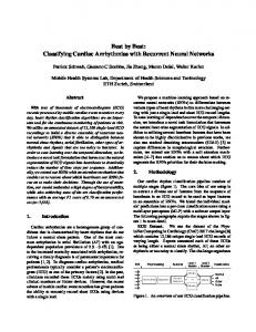
hardware resolution). Observing that combustion events occur, even at maximum engine speed, on a millisecond time scale, a novel and extremely compact and powerful layer-multiplexed bit-serial neuromorphic architecture was developed and exploited for the VLSI CMOS implementation. A. Architecture The required computations can be summarized as a series of parallel multiply and accumulate (MAC) operations interspersed by an occasional nonlinear operation. We exploited five basic stategies to achieve our desired goals: (1) parallel intra-layer topology; (2) single-instructionmultiple-data (SIMD) architecture; (3) bit-serial fixedpoint computational techniques; (4) inter-layer multiplexing of neuron resources; and (5) nonlinearities handled by look-up-tables. The resulting architecture is shown schematically in Figure 1 and consists of: (1) a global controller; (2) a pool of 16 bit-serial neurons; (3) a ROM based bipolar sigmoid activation look-up-table; (4) neuron state registers; and (5) a synaptic weight RAM. In this design, both inputs to the network as well as neuron outputs are stored in the neuron state RAM. When triggered by the global controller, each of the 16 neurons performs the multiply and accumulate (MAC) operation. They receive in a bit serial fashion as input the synaptic weights (from the synaptic weight RAM) and activations from either (a) input nodes or (b) outputs from other neurons and output the accumulated sum of partial products onto a tri-stated bus which is commonly shared by all 16 neurons. Because of the computational nature of neural networks – where information is sequentially computed a layer at a time – only enough neurons are physically implemented in silicon as exist on the layer with the largest number of neurons for all applications of interest. As such, a candidate pool of 16 silicon neurons was chosen. This intra-layer pool of neurons is organized in a SIMD configuration. Single-instruction (SI) means that all active neurons in the pool execute the same instruction at the same time. Multiple-data (MD) means that each active neuron acts on its own slice of data, independently of all other processors. Thus the chip performs fully parallel computations under the supervision of the global controller. A significant reduction in silicon real-estate was achieved by performing inter-layer multiplexing of the 16 neuron
16
16 DATA
NEURON REGISTER RAM (64X16)
10
16
LUT ROM (1Kx10)
BIT-SERIAL NEURONS (16)
BIAS 16 DATA
DATA RUN RST
16 SYNAPTIC WEIGHT RAM (2Kx16)
GLOBAL CONTROLLER
Figure 1. Schematic representation of forward propagation module. pool, i.e., the hardware used in calculating the activations of neurons in one layer is reused for the calculation of neurons in another layer, since neurocomputations are performed a layer at a time. We also used bit-serial algorithms extensively for arithmetic operations because their canonical nature and minimal interconnection requirements make them particularly suitable for efficient VLSI implementation.
GC_PRP
FSM_RUN RE
16
RUN
16
RA RB RC RD
RE
GOPRP RPRP ILAY RLAY RUN GOSTR C RSTR BUSY R
16
16
ANRAM CNRAM AWRAM CWRAM OEBIAS CN
2 16 2 4
R
RO
RA RB RC RD
GC_STR RI
R
RESET
RUN C
CLOCK
ANRAM CNRAM OEN OELUT
16
ANRAM CNRAM OEN OELUT
2 16
R
BUSY
Figure 2. Run-time forward propagation controller. MULTIPLIER ACTF[15:0] WGHT
16
ACCUMULATOR
SOUT
X Y
C
SIN
C
R
NET
10
NET[9:0]
R
CLOCK RESET
Figure 3. Bit-serial neuron. the use of a 16×16 bit fixed-point multiplier. In operation, the multiplier accepts as input either an input stimulus to the neural network or an activation output from a neuron on a previous layer. It multiplies this quantity by the corresponding synaptic weight. The input stimulus (or activation output) is presented to the multiplier in a bitparallel fashion, while the synaptic weights are presented in a bit-serial fashion. The serial output of the multiplier feeds directly into an accumulator. Y[n:0 ] X FSM
C
R
A B C
C. Neurons
FULL ADDER
FULL ADDER
D C
A
FF
Q R
FULL ADDER
A
A FF
Fixed-point bit-serial algorithms for operations such as addition and multiplication are uniquely suitable for efficient VLSI implementations because of their highly compact representations. For example, the size of an n × n bit multiplier scales quadratically (O(n2 )) for a bit-parallel implementation and linearly (O(n)) for a bit-serial one. Bitserial techniques were therefore used. A schematic representation of a bit-serial neuron is shown in Figure 3. Precision constraints for the misfire problem called for
GC_CURREG
INC C
B. Controller At the heart of the neuroprocessor architecture is the global controller. The controller contains the logic to enable the neurochip to execute its task. This task is to load an architecture from RAM, and once triggered, to generate all necessary control signals in addition to orchestrate data movement on-chip and off-chip. When there are no computations being performed, the global controller remains in the idle state, signalling its availability by having the active low BUSY flag set high. When a LOAD command is issued, the controller reads from RAM a neural network topology and goes into an idle state. When the RUN command is subsequently issued, the global controller is in charge of providing control signals to the RAM, ROM, and the 16 on-chip neurons, in order to proceed with the desired computation. Input activations are read out of the 64×16 Neuron State RAM, synaptic weights are read out of the 2K×16 Synaptic Weight RAM, and both are propagated to the bank of 16 neurons. In this way, the global controller keeps track of both intra-layer operations as well as inter-layer operations. Upon completion of a forward pass through the network architecture, the global controller asserts the BUSY flag and returns to the idle state.
ANRAM CNRAM AWRAM CWRAM OEBIAS RUN CN C RI
B
S
D C
CO
CI
FF
Q R
B
S
CO
CI
C
Q R
C
Q R
B
S
CO
CI
FF
FF
D
D
C
FF
Q
D
S
R
Q
D C
R
CLOCK RESET
Figure 4. Bit-serial multiplier of length n. The multiplier shown in Figure 4 is a modified and improved version of a previously reported serial multiplier. Any size multiplier can be formed by cascading the ba-
FULL ADDER
SERIAL IN
A SERIAL OUT
B
S
CO
D
CI Q
Q
C
PARALLEL OUT
R
Q
C
C
R
Q
D
R
RST
R
C
D
R
R
C
Q
D
CLK
C
D
FF
D
Q
Q R
R
C
Q
D
D
C Q
D
C
Q
D
R
R
C
C
R
R
D Q
C D
C
R
Q D
Q
Figure 5. Bit-serial accumulator of length n. sic multiplier cell. The bit-wise multiplication of the multiplier and multiplicand is performed by the AND gates. At each clock cycle, the bank of AND gates compute the partial product terms of the multiplier Y[15:0] and the serial multiplicand X(t). Two’s complement multiplication is achieved by using XOR gates on the outputs of the AND gates. By controlling one of the inputs of the XOR gate, the finite state machine FSM can form the two’s complement of selected terms based on its control flow. In general, for an n × n multiplier (resulting in a 2n bit product), the multiplier can be formed by using 2n basic cells and will perform the multiplication in 2n + 2 clock cycles. Successive operations can be pipelined and the latency of the LSB of the product is n + 2 clock cycles. The accumulator, shown in Figure 5, is also a bit-serial design. It is extremely compact as it consists of a single bit-serial adder linked to a chain of data registers. The length of the accumulator chain is governed by the multiplication length. The multiplier takes 2n + 2 clock cycles to perform a complete n × n multiplication. At each clock cycle, the accumulator sums the bit from the input data stream with both the current contents of the data register on the circular chain as well as any carry bits that might have been generated from the addition in the previous clock cycle. This value is subsequently stored onto the chain on the next clock cycle. This creates a circulating chain of data bits in the accumulator with period 2n + 2. The neuroprocessor design was implemented using HP’s 0.5 µm CMOS design rules. The first generation chip measured 8mm2 in size. The current design operates at a conservative 20 MHz clock speed. A neural application can be loaded into the hardware in under 1 µs. Because of the SIMD architecture, it takes 1.6 µs to simultaneously perform 16 multiply and accumulate operations. This translates into an effective computational throughput of 0.1 µs per MAC operation. The next generation processor will operate at 50 MHz. III. The Misfire Diagnostic Problem Because engine misfire can cause a significant increase in tailpipe emissions and can damage the catalytic converter, it is a required diagnostic. Misfire detection must be performed between engine cylinder firings, which can occur at rates as high as 30,000 events per minute, so that ap-
proximately one billion events must be classified over the life of each vehicle. While there are many ways of detecting engine misfire, all currently practical methods rely on observing engine crankshaft rotational dynamics with a position sensor located at one end of the shaft. Briefly stated, one looks for a crankshaft acceleration deficit following a cylinder firing and attempts to determine whether such a deficit is attributable to a lack of power provided on the most recent firing stroke. The method is complicated by several factors: 1) the crankshaft dynamics are influenced by unregulated inputs from the driver and disturbances introduced through the driveshaft from road irregularities; 2) the dynamics are obscured by measurement noise; 3) the crankshaft is not infinitely stiff and exhibits complex dynamics which mask the signature of the misfire event and which are influenced by the event itself. In effect, we are observing the torsional oscillations of a nonlinear oscillator with driving forces applied at several locations along its main axis. While it is straightforward to write down dynamical equations that approximate the crankshaft rotational dynamics as a function of the combustion pressures applied to the piston faces, it is difficult to solve those equations and even more difficult to solve the inverse inference problem associated with misfire diagnostics. Nonetheless, it was the expectation of a discoverable dynamic relationship between the observed accelerations and the driving forces in this system, coupled with the absence of a satisfactory alternative approach, that motivated our exploration of recurrent networks as a solution to the problem. A. Network and Training Details We used the network architecture 4-15R-7R-1, i.e., 4 inputs, fully recurrent hidden layers with 15 and 7 nodes, and a single output node. All activation functions were bipolar sigmoids. The network executes once per cylinder event (e.g., 8 times per engine cycle for an 8-cylinder engine). The inputs at time step k are the crankshaft acceleration (ACCEL, averaged over the last 90 degrees of crankshaft rotation), engine load (LOAD, computed from the mass flow of air), the engine speed (RPM), and a cylinder identification signal (CID, e.g., 1 for cylinder 1, 0 otherwise), which allows the network to synchronize with the engine cylinder firing order. This network contains 469 weights; thus one execution of the network requires 469 multiplyaccumulate operations and 23 evaluations of the activation function. This computational load (187,000 MAC s−1 ) may be excessive for an already heavily loaded existing processor. Training recurrent networks often poses practical difficulties, primary among which is dealing with the recency effect, i.e., the tendency of a learning network to favor recent training examples at the expense of those previously encountered. To mitigate this difficulty we devised the multistream training technique (Feldkamp and Puskorius, 1994). This technique is especially effective when weight updates are performed using the extended Kalman filter method. Experiments suggest that the present results would not easily have been obtained with the methods more commonly
1000 500 0 -500 (a) Acceleration values
-1000 1 0.5 0 -0.5
(b)Neurochip output -1 0
100
200
300
400
500
600
700
Events
Figure 6. Panel (a) is a temporal stream of acceleration values, illustrating the effects of crankshaft dynamics. This data segment was not used in training the network (it was acquired after the network had been trained). Misfires are denoted by symbols ‘x’. In the absence of torsional oscillations, the misfires would lie clearly below 0 on the vertical scale. Panel (b) displays the corresponding outputs of a trained recurrent network implemented in VLSI. available. The database used for network training was acquired by operating a production vehicle over a wide range of operation, including engine speed-load combinations that would rarely be encountered in normal driving. Misfire events are deliberately introduced (typically by interrupting the spark) at both regular and irregular intervals. Though in this case the data set used for training consists of more than 600,000 examples (one per cylinder event), it necessarily only approximates full coverage of the space of operating conditions and possible misfire patterns. Hence it is important to carry out a careful analysis of generalization. IV. Results and Conclusions For testing, the chip was placed on a PC board and interfaced to the engine processor. The weights of a pretrained network for misfire detection were loaded and the vehicle was driven on the test track. Since the chip required less than 80 µs to execute the 4-15R-7R-1 network, real-time requirements were easily met. Results were logged for a challenging range of vehicle operation and patterns of artificially induced misfire. Figure 6a illustrates cylinder-by-cylinder crankshaft accelerations. The data segment selected corresponds to an engine speed of approximately 4500 revolutions per minute; together with the high rate of artificially induced misfire
(about 25%), this represents a very difficult test of any misfire classifier. If the plotted points had not been labeled, it would certainly not have been obvious which correspond to misfire. Simple filtering of the acceleration series, even on a cylinder-specific basis, is not capable of separating the misfires from the normals. As we hypothesized initially, however, a recurrent network is capable of performing a sort of nonlinear deconvolution of the torsional-oscillationcorrupted acceleration values to perform the separation. (We have also experimented with feedforward networks with delay-lines on the inputs. The results have been less satisfactory.) Figure 6b shows the neural network outputs from the chip. These are very close to the corresponding values from the network implemented in software (with floating-point arithmetic). Both implementations effectively separate misfires from normal events. The rate of misclassifications made by the network (here about 1%) is well within the acceptable range. V. Acknowledgements The research described in this paper was performed by the Center for Space Microelectronics Technology, Jet Propulsion Laboratory, California Institute of Technology, and was sponsored by the National Aeronautics and Space Administration, Office of Space Science.
VI. References Tawel, R., Aranki, N., Feldkamp, L. A. and Marko, K. A. (1998) Ultra-compact Neuroprocessor for Automotive Diagnostics and Control. Proceedings of the Neurap’98 Conference, Marseille, France. Tawel, R. (1997) A Novel Bit-Serial Neuroprocessor Architecture. JPL New Technology Report. Tawel, R., Aranki, N., Puskorius, G., James, J. V., Marko, K. A., Feldkamp, L. A. (1997) Neuroprocessor for Detecting Misfire in an Automotive Engine. NASA Tech Briefs Vol. 21, No. 12, pp. 60–61. Feldkamp, L. A. and G. V. Puskorius (1994) Training controllers for robustness: multi-stream DEKF. Proc. of the IEEE ICNN Orlando, FL, pp. 2377–2382. Marko, K. A., J. V. James, T. M. Feldkamp, G. V. Puskorius, L. A. Feldkamp, and D. Prokhorov (1996) Training recurrent networks for classification: realization of automotive engine diagnostics. Proc. of the WCNN, San Diego, CA, pp. 845-850. Puskorius, G. V., L. A. Feldkamp, and L. I. Davis, Jr. (1996) Dynamic Neural Network Methods Applied to Onvehicle Idle Speed Control. Proc. of the IEEE, vol. 84, no. 10, pp. 1407–1420. Feldkamp, L. A. and G. V. Puskorius (1994) Training Controllers for Robustness: Multi-stream DEKF. Proceedings of the IEEE International Conference on Neural Networks, Orlando, pp. 2377–2382. Marko, K. A., J. V. James, T. M. Feldkamp, G. V. Puskorius, and L. A. Feldkamp. (1996b) Signal Processing by Neural Networks to Create “Virtual” Sensors and Model-Based Diagnostics. Proc. of the International Conference on Artificial Neural Networks (ICANN’96), Bochum, Germany, pp. 191-196. Marko, K. A., J. V. James, T. M. Feldkamp, G. V. Puskorius, L. A. Feldkamp, and D. Prokhorov (1996c) Training Recurrent Networks for Classification: Realization of Automotive Engine Diagnostics. Proc. of the World Congress on Neural Networks (WCNN’96), San Diego, CA, pp. 845-850. Puskorius, G. V. and L. A. Feldkamp (1994) Neurocontrol of Nonlinear Dynamical Systems with Kalman FilterTrained Recurrent Networks. IEEE Transactions on Neural Networks 5, pp. 279-297. Puskorius, G. V., L. A. Feldkamp, and L. I. Davis, Jr. (1996) Dynamic neural network methods applied to onvehicle idle speed control. Proceedings of the IEEE, vol. 84, no. 10, pp. 1407–1420. Puskorius, G. V. and L. A. Feldkamp (1996) Signal processing by dynamic neural networks with application to automotive misfire detection. Proceedings of the 1996 World Congress on Neural Neural Networks, San Diego, pp. 585– 590. Singhal, S. and L. Wu (1989) Training Multilayer Perceptrons with the Extended Kalman algorithm, In D. S. Touretzky (ed) Advances in Neural Information Processing Systems 1, pp. 133–140. San Mateo, CA: Morgan Kaufmann.