tions, and edges represent first-in-first-out (FIFO) channels for storing data values (tokens) and imposing data dependencies between actors. In DSP-oriented ...
Dataflow-based Design and Implementation of Image Processing Applications∗ Chung-Ching Shen, William Plishker, and Shuvra S. Bhattacharyya Department of Electrical and Computer Engineering, and Institute for Advanced Computer Studies University of Maryland, College Park, Maryland, USA {ccshen, plishker, ssb}@umd.edu
Abstract Dataflow is a well known computational model and is widely used for expressing the functionality of digital signal processing (DSP) applications, such as audio and video data stream processing, digital communications, and image processing. These applications usually require real-time processing capabilities and have critical performance constraints. Dataflow provides a formal mechanism for describing specifications of DSP applications, imposes minimal datadependency constraints in specifications, and is effective in exposing and exploiting task or data level parallelism for achieving high performance implementations. To demonstrate dataflow-based design methods in a manner that is concrete and easily adapted to different platforms and back-end design tools, we present in this report a number of case studies based on the lightweight dataflow (LWDF) programming methodology. LWDF is designed as a ”minimalistic” approach for integrating coarse grain dataflow programming structures into arbitrary simulation- or platform-oriented languages, such as C, C++, CUDA, MATLAB, SystemC, Verilog, and VHDL. In particular, LWDF requires minimal dependence on specialized tools or libraries. This feature — together with the rigorous adherence to dataflow principles throughout the LWDF design framework — allows designers to integrate and experiment with dataflow modeling approaches relatively quickly and flexibly into existing design methodologies and processes.
1
Dataflow Introduction
Model-based design has been explored extensively over the years in many domains of embedded systems. In model-based design, application subsystems are represented in terms of functional components that interact through formal models of computation (e.g., see [1]). By exposing and exploiting high level application structure that is often difficult to extract from platform-based design tools, model-based approaches facilitate systematic integration, analysis, synthesis, and optimization that can be used to exploit platform-based tools and devices more effectively. Dataflow is a well known computational model and is widely used for expressing the functionality of digital signal processing (DSP) applications, such as audio and video data stream processing, digital communications, and image processing (e.g., see [2, 3, 4]). These applications usually require real-time processing capabilities and have critical performance constraints. Dataflow ∗
Technical Report UMIACS-TR-2011-11, Institute for Advanced Computer Studies, University of Maryland at College Park, 2011. A version of this report is to appear in L. Guan, Y. He, and S-Y. Kung, editors, Multimedia Image and Video Processing. CRC Press, second edition.
1
provides a formal mechanism for describing specifications of DSP applications, imposes minimal data-dependency constraints in specifications, and is effective in exposing and exploiting task or data level parallelism for achieving high performance implementations. Dataflow models of computation have been used in a wide variety of development environments to aid in the design and implementation of DSP applications (e.g., see [1, 5, 6, 7]). In these tools, an application designer is able to develop complete functional specifications of model-based components, and functional validation or implementation on targeted platforms can be achieved through automated system simulation or synthesis processes. Dataflow graphs are directed graphs, where vertices (actors) represent computational functions, and edges represent first-in-first-out (FIFO) channels for storing data values (tokens) and imposing data dependencies between actors. In DSP-oriented dataflow models of computation, actors can typically represent computations of arbitrary complexity as long as the interfaces of the computations conform to dataflow semantics. That is, dataflow actors produce and consume data from their input and output edges, respectively, and each actor executes as a sequence of discrete units of computation, called firings, where each firing depends on some well-defined amount of data from the input edges of the associated actor. Retargetability is an important property to integrate into dataflow-based design environments for DSP. The need for efficient retargetability is of increasing concern due to the wide variety of platforms that are available for targeting implementations under different kinds of constraints and requirements. Such platforms include, for example, programmable digital signal processors, field programmable gate arrays (FPGAs), and graphics processing units (GPUs). For efficient exploration of implementation trade-offs, designers should be able to rapidly target these kinds of platforms for functional prototyping and validation. For example, Sen et al. introduced a structured, dataflow-based design methodology for mapping rigid image registration applications onto FPGA platforms under real-time performance constraints [4]. Shen et al. presented a method to derive Pareto points in the design space that provide trade-offs between memory usage and performance based on different scheduling strategies [8]. This approach to derive such Pareto points demonstrates a systematic, retargetable methodology based on high level dataflow representations. By following structured design methods enabled by dataflow modeling, designers can efficiently port implementations of dataflow graph components (actors and FIFOs) across different platformoriented languages, such as C, C++, CUDA, MATLAB, SystemC, Verilog, and VHDL, while the application description can still be tied as closely as possible to the application domain, not the target platform. This makes a dataflow-based design highly portable while still structured enough to be optimized for. For example, in [8], a dataflow-based design tool is introduced for design and analysis of embedded software for multimedia systems. In this tool, exploitation of data parallelism can be explored efficiently and associated performance metrics are evaluated for different dataflow graph components that are implemented using different platform-oriented languages. By promoting formally specified component interfaces (in terms of dataflow semantics), and modular design principles, dataflow techniques also provide natural connections to powerful unit testing methodologies, as well as automated, unit-testing-driven correspondence checking between different implementations of the same component (e.g., see [9, 10]). To demonstrate dataflow-based design methods in a manner that is concrete and easily adapted to different platforms and back-end design tools, we present case studies based on the lightweight dataflow (LWDF) programming methodology [11]. LWDF is designed as a “minimalistic” approach for integrating coarse grain dataflow programming structures into arbitrary simulation- or platformoriented languages, such as those listed above (i.e., C, C++, CUDA, etc.). In particular, LWDF requires minimal dependence on specialized tools or libraries. This feature — together with the rigorous adherence to dataflow principles throughout the LWDF design framework — allow design2
ers to integrate and experiment with dataflow modeling approaches relatively quickly and flexibly into existing design methodologies and processes. Thus, LWDF is well suited for presenting case studies in the context of this report, where our objective is to emphasize fundamental dataflow concepts and features, and their connection to developing efficient parallel implementations of image processing applications. In this report, we provide background on relevant dataflow concepts and LWDF programming, and present LWDF-based case studies that demonstrate effective use of dataflow techniques for image processing systems. We focus specifically on case studies that demonstrate the integration of dataflow programming structures with C, Verilog, and CUDA for simulation, FPGA mapping, and GPU implementation, respectively.
2
Overview of Dataflow Models
In this section, we review a number of important forms of dataflow that are employed in the design and implementation of DSP systems. Synchronous Dataflow (SDF) [3] is a specialized form of dataflow that is useful for an important class of DSP applications, and is used in a variety of commercial design tools. In SDF, actors produce and consume constant amounts of data with respect to their input and output ports. Useful features of SDF include compile-time, formal validation of deadlock-free operation and bounded buffer memory requirements; support for efficient static scheduling; and buffer size optimization (e.g., see [12]). Cyclo-static Dataflow (CSDF) [13] is a generalization of SDF where the consumption or production rate of an actor port forms a periodic sequence of constant values. Both SDF and CSDF are static dataflow models in which production and consumption rates are statically known and data-independent. The Parameterized Synchronous Dataflow (PSDF) model of computation results from the integration of SDF with the meta-modeling framework of parameterized dataflow [14]. PSDF expresses a wide range of dynamic dataflow behaviors while preserving much of the useful analysis and synthesis capability of SDF [14]. Based on the scheduling features provided by PSDF, low-overhead, quasi-static schedules can be generated for hand-coded implementation or software synthesis. Here, by a quasi-static schedule, we mean an ordering of execution for the dataflow actors whose structure is largely fixed at compile time, with a relatively small amount of decision points or symbolic adjustments evaluated at run-time based on the values of relevant input data. Boolean Dataflow (BDF) [15] allows data-dependent control actors to be integrated with SDF actors. In BDF, the consumption and production rates of an actor port can vary dynamically based on the values of tokens that are observed at a designated control port of the actor. Two basic control actors in the BDF model are the switch and select actors. The switch actor has two input ports — one for control and another for data — and two output ports. On each firing, the actor consumes one token from its data input, and one Boolean-valued token from its control input, and copies the value consumed from its data input onto one of its two output ports. The output port on which data is produced during a given firing is selected based on the Boolean value of the corresponding control input token. In contrast, the select actor has two data input ports, one control input port, and one output port. On each firing, the actor consumes a Boolean-valued token from its control input, and selects a data input based on the value of this control token. The actor then consumes a single token from the selected data input, and copies this token onto the single actor output port. Enable-Invoke Dataflow (EIDF) is a recently proposed dataflow model [16] that facilitates the design of applications with structured dynamic behavior. EIDF divides actors into sets of modes.
3
Each mode, when executed, consumes and produces a fixed number of tokens. The fixed behavior of a mode provides structure that can be exploited by analysis and optimization tools, while dynamic behavior can be achieved by switching between modes at run-time. Each mode is defined by an enable method and an invoke method, which correspond, respectively, to testing for sufficient input data and executing a single quantum (“invocation”) of execution for a given actor. After a successful invocation, the invoke method returns a set of admissible next modes, any of which may be then checked for readiness using the enable method and then invoked, and so on. By returning a set of possible next modes (as opposed to being restricted to a single next mode), a designer may model non-deterministic applications in which execution can proceed down many possible paths. In the implementation of dataflow tools, functionalities corresponding to the enable and invoke methods are often interleaved — for example, an actor firing may have computations that are interleaved with blocking reads of data that provide successive inputs to those computations. In contrast, there is a clean separation of enable and invoke capabilities in EIDF. This separation helps to improve the predictability of an actor invocation (since availability of the required data can be guaranteed in advance by the enable method), and in prototyping efficient scheduling and synthesis techniques (since enable and invoke functionality can be called separately by the scheduler). Dynamic dataflow behaviors require special attention in scheduling to retain efficiency and minimize loss of predictability. The enable function is designed so that if desired, one can use it as a “hook” for dynamic or quasi-static scheduling techniques to rapidly query actors at runtime to see if they are executable. For this purpose, it is especially useful to separate the enable functionality from the remaining parts of actor execution. These remaining parts are left for the invoke method, which is carefully defined to avoid computation that is redundant with the enable method. The restriction that the enable method operates only on token counts within buffers and not on token values further promotes the separation of enable and invoke functionalities while minimizing redundant computation between them. At the same time, this restriction does not limit the overall expressive power of EIDF, which is Turing complete. This can be seen from our ability to formulate enabling and invoking methods for BDF actors [16]. Since BDF is known to be Turing complete, and EIDF is at least as expressive as BDF, EIDF can express any computable function, including conditional dataflow behaviors, and other important forms of dynamic dataflow. The restrictions in EIDF can therefore be viewed as design principles imposed in the architecture of dataflow actors rather than restrictions in functionality. Such principles lay the foundation for optimization and synthesis tools to effectively target a diverse set of platforms including FPGAs, GPUs, and other kinds of multi-core processors. The LWDF programming approach, which is used as a demonstration vehicle throughout this report, is based on the Core Functional Dataflow (CFDF) model of computation [16, 17]. CFDF is a special case of the EIDF model. Recall that in EIDF, the invoking function in general returns a set of valid next modes in which the actor can subsequently be invoked. This allows for nondeterminism as an actor can be invoked in any of the valid modes within the next-mode set. In the deterministic CFDF model, actors must proceed deterministically to one particular mode of execution whenever they are enabled. Hence, the invoking function should return only a single valid mode of execution instead of a set of arbitrary cardinality. In other words, CFDF is the model of computation that results when EIDF is restricted so that the set of next modes always has exactly one element. With this restricted form of invoking function, only one mode can meaningfully be interrogated by the enabling function, ensuring that the application is deterministic.
4
3
Lightweight Dataflow
Lightweight dataflow (LWDF) is a programming approach that allows designers to integrate various dataflow modeling approaches relatively quickly and flexibly into existing design methodologies and processes [11]. LWDF is designed to be minimally intrusive on existing design processes and requires minimal dependence on specialized tools or libraries. LWDF can be combined with a wide variety of dataflow models to yield a lightweight programming method for those models. In this report, the combination of LWDF and the CFDF model is used to demonstrate model-based design and implementation of image processing applications, and we refer this method to as lightweight core functional dataflow (LWCFDF) programming. In LWCFDF, an actor has an operational context (OC ), which encapsulates the following entities related to an actor implementation: • Actor parameters. • Local actor variables — variables whose values store temporary data that does not persist across actor firings. • Actor state variables — variables whose values do persist across firings. • References to the FIFOs corresponding to the input and output ports (edge connections) of the actor as a component of the enclosing dataflow graph. • Terminal modes: a (possibly empty) subset of actor modes in which the actor cannot be fired. In LWCFDF, the OC for an actor also contains a mode variable whose value stores the next CFDF mode of the actor and persists across firings. The LWCFDF operational context also includes references to the invoke function and enable function of the actor. The concept of terminal modes, defined above, can be used to model finite subsequences of execution that are “re-started” only through external control (e.g., by an enclosing scheduler). This is implemented in LWCFDF by extending the standard CFDF enable functionality such that it unconditionally returns false whenever the actor is in a terminal mode. An example of a terminal mode is given in Section 4 as part of the specification of a Gaussian filtering application.
3.1
Design of LWCFDF Actors
Actor design in LWCFDF includes four interface functions — the construct, enable, invoke, and terminate functions. The construct function can be viewed as a form of object-oriented constructor, which connects an actor to its input and output edges (FIFO buffers), and performs any other preexecution initialization associated with the actor. Similarly, the terminate function performs any operations that are required for “closing out” the actor after the enclosing graph has finished executing (e.g., deallocation of actor-specific memory or closing of associated files). To describe LWCFDF operation (including the general operation of the underlying CFDF model of computation) in more detail, we define the following notation for dataflow graph actors and edges. • inputs(a): the set of input edges for actor a. If a is a source actor, then inputs(a) = ∅. • outputs(a): the set of output edges for actor a. If a is a sink actor, then outputs(a) = ∅. • population (e): the number of tokens that reside in the FIFO associated with e at a given time (when this time is understood from context). 5
• capacity (e): the buffer size associated with e — that is, the maximum number of tokens that can coexist in the FIFO associated with e. • cons(a, m, e): the number of tokens consumed on input edge e in mode m of a given actor a. • prod (a, m, e): the number of tokens produced on output edge e in mode m of a given actor a. • τ (a): the set of terminal modes of actor a. In LWCFDF, a finite buffer size capacity (e) must be defined for every edge at any point during execution. Typically, this size remains fixed during execution, although in more complex or less predictable applications, buffer sizes may be varied dynamically. For simplicity, this optional time-dependence of capacity (e) is suppressed from our notation. Further discussion of dynamically varying buffer sizes is beyond the scope of this report. In the enable function for an LWCFDF actor a, a true value is returned if population (e) ≥ cons(a, m, e) for all e ∈ inputs(a);
(1)
population(e) ≤ (capacity (e) − prod (a, m, e)) for all e ∈ outputs(a); and
(2)
m∈ / τ (a),
(3)
where m is the current mode of a. In other words, the enable function returns true if the given actor is not in a terminal mode, and has sufficient input data to execute the current mode, and the output edges of the actor have sufficient data to store the new tokens that are produced when the mode executes. An actor can be invoked at a given point of time if the enable function is true-valued at that time. In the invoke function of an LWCFDF actor a, the operational sequence associated with a single invocation of a is implemented. Based on CFDF semantics, an actor proceeds deterministically to one particular mode of execution whenever it is enabled, and in any given mode, the invoke method of an actor should consume data from at least one input or produce data on at least one output (or both) [16]. Note that in case an actor includes state, then the state can be modeled as a self-loop edge (a dataflow edge whose source and sink actors are identical) with appropriate delay, and one or more modes can be defined that produce or consume data only from the self-loop edge. Thus, modes that affect only the actor state (and not the “true” inputs or outputs of the actor) do not fundamentally violate CFDF semantics, and are therefore permissible in LWDF. The enable and invoke functions of LWCFDF actors are executed by schedulers in the LWCFDF runtime environment. When an enclosing scheduler executes an LWCFDF application, each actor starts in an initial mode that is specified as part of the application specification. When the invoke function for an actor a completes, it returns the next mode for a to the runtime environment. This next mode information can then be used for subsequent checking of enabling conditions for a.
3.2
Design of LWCFDF FIFOs
FIFO design for dataflow edge implementation is orthogonal to the design of dataflow actors in LWDF. That is, by using LWDF, application designers can focus on design of actors and mapping of edges to lower level communication protocols through separate design processes (if desired) and integrate them later through well-defined interfaces. Such design flow separation is useful due
6
to the orthogonal objectives, which center around computation and communication, respectively, associated with actor and FIFO implementation. FIFO design in LWDF typically involves different structures in software compared to hardware. For software design in C, tokens can have arbitrary types associated with them — e.g., tokens can be integers, floating point values, characters, or pointers (to any kind of data). Such an organization allows for flexibility in storing different kinds of data values, and efficiency in storing the data values directly (i.e., without being encapsulated in any sort of higher-level “token” object). In C-based LWCFDF implementation, FIFO operations are encapsulated by interface functions in C. These functions are referenced through function pointers so that they can be targeted to different implementations for different FIFO types while adhering to standard interfaces (polymorphism). Standard FIFO operations in LWDF include operations that perform the following tasks. • Create a new FIFO with a specified capacity; • read and write tokens from and to a FIFO; • check the capacity of a FIFO; • check the number of tokens that are currently in a FIFO; • deallocate the storage associated with a FIFO (e.g., for dynamically adapting graph topologies or, more commonly, as a termination phase of overall application execution). For hardware design using hardware description languages (HDLs), a dataflow graph edge is typically mapped to a FIFO module, and LWCFDF provides designers with mechanisms for developing efficient interfaces between actor and FIFO modules. For maximum flexibility in design optimization, LWCFDF provides for retargetability of actor-FIFO interfaces across synchronous, asynchronous, and mixed-clock implementation styles.
4
Simulation Case Study
As an example of using the LWDF programming model based on the CFDF model of computation for DSP software design using C, a C-based LWCFDF actor is implemented as an abstract data type (ADT) to enable efficient and convenient reuse of the actor across arbitrary applications. Such ADTs provide object-oriented implementations in C. In particular, an actor context is encapsulated with a separation of interface and implementation. Furthermore, by building on memory layout conventions of C structures, an actor context inherits from an actor design template that contains common (or “base class”) types that are shared across actors. Similarly, through the use of function pointers, different execution contexts for a related group of actors can share the same name (e.g., as a “virtual method”). In typical C implementations, ADT components include header files to represent definitions that are exported to application developers and implementation files that contain implementationspecific definitions. We refer to the ADT-based integration of LWCFDF and C as LWCFDF-C.
4.1
Application Specification
To demonstrate LWDF in a C-based design flow, we create a basic application centered around Gaussian filtering. Two-dimensional Gaussian filtering is a common kernel in image processing 7
45$64!$"&+' ,-&$%+%$./$%' !"#$%&*+,-./& !"#$%&*+,-./& ()*+,-$ !"#$%&'()& +%$./$%' $&'()&
!"#$%&'
$&'()& !"#$%&'()&
1.233!."+,-&$%'
!"#$%&'()& ()*+,-$ $&'()& +0%!&$%'
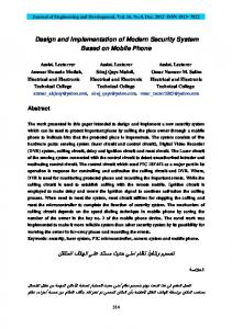
Figure 1: Dataflow graph of an image processing application for Gaussian filtering. that is used for pre-processing. Gaussian filtering can be used to denoise an image or to prepare for multiresolution processing. A Gaussian filter is a filter whose impulse response is a Gaussian curve, which in two dimensions resembles a bell. For filtering in digital systems, the continuous Gaussian filter is sampled in a window and stored as coefficients in a matrix. The filter is convolved with the input image by centering the matrix on each pixel, multiplying the value of each entry in the matrix with the appropriate pixel, and then summing the results to produce the value of the new pixel. This operation is repeated until the entire output image has been created. The size of the matrix and the width of the filter may be customized according to the application. A wide filter will remove noise more aggressively but will smoothen sharp features. A narrow filter will have less of an impact on the quality of the image, but will be correspondingly less effective against noise. Figure 1 shows a simple application based on Gaussian filtering. It reads bitmap files in tile chunks, inverts the values of the pixels of each tile, runs Gaussian filtering on each inverted tile, and then writes the results to an output bitmap file. The main processing pipeline is single-rate in terms of tiles, and can be statically scheduled, but after initialization and end-of-file behavior is modeled, there is conditional dataflow behavior in the application graph, which is represented by square brackets in the figure. Such conditional behavior arises, first, because the Gaussian filter coefficients are programmable to allow for different standard deviations. The coefficients are set once per image — coefficient filter reader produces a coefficient matrix for only the first firing. To correspond to this behavior, the gaussian filter actor consumes the coefficient matrix only once, and each subsequent firing processes tiles. Such conditional firing also applies to bmp file reader, which produces tiles until the end of the associated file is reached. It should also be noted that the tiles indicated in Figure 1 do vary somewhat between edges. Gaussian filtering applied to tiles must consider a limited neighborhood around each tile (called a halo) for correct results. Therefore, tiles produced by bmp file reader overlap, while the halo is discarded after Gaussian filtering. As a result, non-overlapping tiles form the input to bmp file writer.
4.2
Actor Design using LWCFDF-C
As shown in Figure 1, our dataflow model of the image processing application for Gaussian filtering includes five actors: bmp file reader, coefficient filter reader, invert, gaussian filter, and bmp file writer. Design and implementation of each actor using LWCFDF-C is described below. The bmp file reader actor contains two modes: the process mode and the inactive mode.
8
In the process mode, for each firing when the bmp file reader actor is enabled, it reads image pixels of the processing tile and the corresponding header information from a given bitmap file, and produces them to its output FIFOs. Then the actor returns the process mode as the mode for its next firing. This continues for each firing until all of the data has been read from the given bitmap file. After that, the actor returns the inactive mode, which is a terminal mode (see Section 3), and therefore indicates that the actor cannot be fired anymore until its current mode is first reset externally (e.g., by the enclosing scheduler). In other words, the inactive mode is in the terminal mode set of the bmp file reader. The coefficient filter reader actor contains two modes: the process mode and the inactive mode. Again, the inactive mode is a terminal mode. For each firing when it is enabled (not in the inactive mode), the coefficient filter reader actor reads filter coefficients from a given file, stores them into a filter coefficient vector (FCV) array, and produces the coefficients onto its output FIFO. The FCV V has the form V = (sizeX, sizeY, c0 , c1 , . . . , cn ),
(4)
where sizeX and sizeY denote the size of the FCV represented in two dimensional format; each ci represents a coefficient value; and n = sizeX × sizeY. After firing, the actor returns the process mode if there is data remaining in the input file; otherwise, the actor returns the inactive mode. The bmp file writer actor contains only a single mode, called the process mode. Thus, the actor behaves as an SDF actor. For each firing when it is enabled, the bmp file writer actor reads the processed image pixels of the processing tile and the corresponding header information from its input FIFOs, and writes them to a bitmap file, which can later be used to display the processed results. The actor returns the process mode as the next mode for firing. The invert actor contains only the process mode which makes the actor implemented as an SDF actor. For each firing when it is enabled, the invert actor reads the image pixels of the processing tile from its input FIFOs, inverts the color of the image pixels, and writes the processed result to its output FIFO. The actor returns the process mode as the next mode for firing. The gaussian filter actor contains two modes: the store coefficients STC mode and the process mode. In the STC mode, for each firing when it is enabled, the gaussian filter actor consumes filter coefficients from its coefficient input FIFO, caches them inside the actor for further reference, and then returns the process mode as the next mode for firing. In the process mode, for each firing when the gaussian filter actor is enabled, image pixels of a single tile will be consumed from the tile input FIFO of the actor and the cached filter coefficients will be applied to these pixels. The results will be produced onto the tile output FIFO. The actor then returns the process mode as the next mode for firing. To activate a new set of coefficients, the actor must first be reset, through external control, back to the STC mode. To demonstrate how actors are designed using LWCFDF-C, we use the gaussian filter actor as a design example, and highlight the core implementation parts of the construct function and enable function in the following code segments.
9
/* actor operational context */ gfilter_cfdf_context_type *context = NULL; context = util_malloc(sizeof(gfilter_cfdf_context_type)); /* actor enable function */ context->enable = (actor_enable_function_type)gfilter_cfdf_enable; /* actor invoke function */ context->invoke = (actor_invoke_function_type)gfilter_cfdf_invoke; context->mode = STC_MODE; context->filter = NULL; context->filterX = 0; context->filterY = 0; context->tileX = tileX; context->tileY = tileY; context->halo = halo; context->coef_in = coef_in; context->tile_in = tile_in; context->tile_out = tile_out;
/* /* /* /* /* /* /* /* /* /*
initial mode configuration */ pointer to filter coefficients */ size of filter coefficients X dimension */ size of filter coefficients Y dimension */ length of the tile */ height of the tile */ halo padding around tile dimensions */ coef input */ tile input */ tile output */
boolean result = FALSE; switch (context->mode) { case STC_MODE: /* Store Coefficients Mode */ result = disps_fifo_population(context->coef_in) >= 1; break; case PROCESS_MODE: /* Process Mode */ result = disps_fifo_population(context->tile_in) >= 1; break; default: result = FALSE; break; } return result;
The invoke function implements the core computation of the gaussian filter actor. The functionality of the corresponding modes is shown in the following code segments.
10
switch (context->mode) { case STC_MODE: fifo_read(context->coef_in, &fcv); /* first element of fcv stores the size of the filter. */ context->filterY = fcv[0]; context->filterX = fcv[1]; context->filter = util_malloc(sizeof(float) * context->filterY * context->filterX); for (x = 0; x < context->filterY * context->filterX; x++) { context->filter[x] = fcv[x + 2]; } sum_coefs = 0; for (x = 0; x < context->filterY* context->filterX; x++) { sum_coefs += context->filter[x]; } for (x = 0; x < context->filterY * context->filterX; x++) { context->filter[x] /= sum_coefs; } context->mode = PROCESS_MODE; break;
11
case PROCESS_MODE: fifo_read(context->tile_in, &tile); /* form a new tile */ newtile = malloc(sizeof(float) * (tileX) * (tileY)); /* loop through the pixels in the tile */ for (x = 0; x < tileX; x++) { for (y = 0; y < tileY; y++) { int yf, xf; newtile[(tileX) * y + x] = 0; /*loop through the coefs of the filter*/ for (yf = 0; yf < context->filterY; yf++) { for (xf = 0; xf < context->filterX; xf++) { newtile[(tileX) * y + x] += context->filter[yf * context->filterX + xf] * tile[(tileX + 2 * halo) * (y + yf) + (x + xf)]; } } } } fifo_write(context->tile_out, &newtile); context->mode = PROCESS_MODE; break;
Functional correctness of the LWCFDF design for the Gaussian filtering application can be verified by simulating its LWCFDF-C implementation using a simple scheduling strategy, which is an adaptation of the canonical scheduling strategy of the functional DIF environment [17]. Since the semantics of LWCFDF dataflow guarantee deterministic operation (i.e., the same input/output behavior regardless of the schedule that is applied), validation under such a simulation guarantees correct operation regardless of the specific scheduling strategy that is ultimately used in the final implementation. Such a simulation approach is therefore useful to orthogonalize functional validation of an LWDF design before exploring platform-specific scheduling optimizations — e.g., optimizations that exploit the parallelism exposed by the given dataflow representation. This approach is also useful because it allows use of a standard, “off-the-shelf” scheduling strategy (the canonical scheduling adaptation described above) during functional validation so that designer effort on scheduling can be focused entirely on later phases of the design process, after functional correctness has been validated.
12
/K�
/K�
/K�
/K�
/K�
/K�
/K�
/K� �>�
�>�
�>� /K�
Z�D
/K�
/K�
/K� �>�
�>�
�>� /K�
/K�
/K�
/K�
Z�D �>�
�>�
�>�
/K�
/K�
�ůŽĐŬ DĂŶĂŐĞŵĞŶƚ
/K�
/K�
/K�
/K�
Figure 2: A typical FPGA architecture. 123)
6&0"7#&!) 425)
425) 123)
6&0"7#&!) 425)
!"#$%&'()*+,) (*!!-)./0"()
123)
6&0"7#&!) 425)
425) 123)
6&0"7#&!)
Figure 3: Simplified Xilinx Virtex-6 FPGA CLB [19].
5 5.1
Background on FPGAs for Image Processing FPGA Overview
A field-programmable gate array (FPGA) is a type of semiconductor device containing a regular matrix of user programmable logic elements whose interconnections are provided through a programmable routing network [18]. FPGAs can be easily configured to implement custom hardware functionalities. FPGAs provide for relatively low cost, and fast design time compared to implementation on application-specific integrated circuits (ASICs) with generally some loss in performance and energy efficiency. However, even when ASIC implementation is the ultimate objective, use of FPGAs is effective for rapid prototyping and early stage design validation. A typical FPGA architecture, which is shown in Figure 2, consists of various mixes of configurable logic blocks, embedded memory blocks, routing switches, interconnects, and subsystems for high-speed I/O, and clock management. Configurable Logic Blocks (CLBs) or Logic Elements (LEs) are the main programmable logic elements in FPGAs for implementing simple or complex combinatorial and sequential circuitry. A typical CLB element contains look-up tables for implementing Boolean functions; dedicated user-controlled multiplexers for combinational logic; dedicated arithmetic and carry logic; and programmable memory elements such as flip flops, registers, or RAMs. An example of a simplified Xilinx Virtex-6 FPGA CLB is shown in Figure 3. 13
Various FPGAs device families include significant support for computationally-intensive DSP tasks. In addition to having higher-performance designs for major logic and memory elements and interconnects, dedicated hardware resources are provided in such FPGAs for commonly-used DSP operations, such as multiply-accumulate (MAC) operations. Furthermore, performance-optimized intellectual property (IP) cores are also incorporated into FPGAs to perform specific DSP tasks, such as FIR filtering and FFT computation.
5.2
Image Processing on FPGAs
Image processing on FPGAs is attractive as many interesting applications, for example in the domains of computer vision, and medical image processing, can now be implemented with high flexibility, relatively low cost, and high performance. This is because many common image processing operations can be mapped naturally onto FPGAs to exploit the inherent parallelism within them. Typical operations for image processing applications include image differencing, registration, and recognition. Real-time image processing often requires DSP algorithms operating on multiple rows or columns of image pixels concurrently. FPGAs can provide extensive capabilities for high-speed, parallel-processing of image pixels. For example, Xilinx’s new FPGA, the Virtex-6, can deliver over 30 billion MAC operations per second for processing pixels in parallel. These elements can also be reconfigured to perform different tasks based on application requirements.
6
FPGA Design Case Study
To illustrate a dataflow-based design for FPGA implementation using the Verilog hardware description language (HDL), we design an LWCFDF actor as a Verilog module, where input and output ports of the actor are mapped to unidirectional module ports. Such an actor-level module can contain arbitrary sub-modules for complex actors, and the functionality of an actor can in general be described in either a behavioral or structural style. We refer to such an integration of LWCFDF with Verilog as LWCFDF-V. Design of an LWCFDF-V actor module can be structured as a finite state machine (FSM) for implementing the associated mode operations, an I/O controller for performing read and write operations on the FIFOs that are connected to the actor, and any number of sub-modules for concurrent execution of processing sub-tasks. In the Gaussian filtering application based on the dataflow graph shown in Figure 1, only the invert and gaussian filtering actors are synthesizable modules. The bmp file read, coefficient filter reader, and bmp file writer actors can be designed for verifying functional correctness of the application in Verilog simulations. The gaussian filter actor in LWCFDF-V has two modes: the STC and process modes. The actor implements the core computation of the Gaussian filtering application. In the STC mode, the actor reads coefficients and stores them into an internal memory. As described in Section 4, this operation under the STC mode is applied only once per image. In the process mode, the gaussian filter actor incorporates a sub-module to exploit parallelism associated with the convolution computations of the filter coefficients and image pixels. A design schematic of this parallel processing component of the LWCFDF-V gaussian filter actor module is shown in Figure 4. As shown in Figure 4, the processing elements for the convolution computations basically consist of levels of multipliers and adders. In order to have efficient hardware implementations for both operations, we apply the Dadda Tree Multiplier (DTM) [20] as the design method for designing 14
WŝdžĞůƐ�ŽĨ�ƚŚĞ�ƉƌŽĐĞƐƐŝŶŐ�ƚŝůĞ
ĨĐǀϬ
ĨĐǀϭ
ĨĐǀϮ
ĨĐǀŶͲϭ
ŵƵůƚŝƉůŝĞƌƐ
͙
WĂƌĂůůĞů�ĐĂƌƌLJ�ůŽŽŬͲĂŚĞĂĚ�ĂĚĚĞƌƐ
ŶĞǁ�ƉŝdžĞů
Figure 4: Parallel processing for tile pixels geared towards FPGA implementation. the multipliers and the Carry Look-ahead Adder (CLA) [21] for the adders. Both design methods provide speed improvements for the respective operations. A Verilog specification of the gfilter filter actor module is illustrated in the following code. This type of structural design provides a useful standard format for designing actor modules in LWCFDF-V.
15
/*************************************************************************** Structural modeling for parallel processing **************************************************************************/ gfilter_process_module gpm(new_pixel, new_pixel_ready, pixel[0], pixel[1], ..., pixel[m-1], fcv[0], fcv[1], ..., fcv[n-1], mode, pixel_ready, clock , reset); /************************************************************************** Behavioral modeling for FSM and I/O control ***************************************************************************/ always @(posedge clock or negedge reset) begin if (~reset) begin /* System reset */ end else begin case (mode) ‘GFILTER_STC_MODE: begin /* sequential operations and state transition */ end ‘GFILTER_PROCESS_MODE: begin /* sequential operations and state transition */ end endcase end end always @(*) begin case (mode) ‘GFILTER_STC_MODE: begin /* combinational operations and state update */ end ‘GFILTER_PROCESS_MODE: begin /* combinational operations and state update */ end endcase end
Functional correctness of the LWCFDF-V design for the Gaussian filtering application can be verified by connecting all of the actor modules with the corresponding FIFO modules in a testbench module, and simulating the LWCFDF-V implementations based on a self-timed scheduling strategy. In such a scheduling strategy, an actor module fires whenever it has sufficient tokens (as required by the corresponding dataflow firing) available on its input FIFOs, and there is no central controller to drive the overall execution flow [22]. To experiment with the LWCFDF-V design, we used the Xilinx Virtex-5 FPGA device. We applied 256x256 images decomposed into 128x128 tiles and filtered with a 5x5 matrix of Gaussian filter coefficients. Based on these settings, 25 DTMs and 23 CLAs were instantiated for parallel processing. The synthesis result derived from the LWCFDF implementation of the gaussian filter 16
"##$%!&'!()*+,#)!-#&.)//&#/!
!
!$%&'($)"(,0$11234)#32& !"#
!
!
!$%&'($)*$+,(-
!"#
!
!"#
!
!
"./
!
"./
!
"./
…!
"(,0$11234).5$+$3&)/5'1&$(!
!
631&('07,3)*$+,(-
!
89:($;)