connectedness, provide more useful information than geometric data. and ... If we restrict our consideration to objects with planar maximal connected faces, the ...
Decomposin@ a Solid Object into Elementary Features Leila De Floriani Elisabetta Bruzzone Istituto per la Matematica Applicata - Consiglio Nazionale delle Ricerche Via L.B. Alberti, 4 - 16132 Genova (Italy)
Abstract
We describe an algorithm for extracting form features, like protrusions or depressions on a face, through-holes or handles, from a relational boundary model of a solid object, called the Symmetric Boundary Graph (SBG). The method is based on loop identification and connected component labeling on the SBG and produces a decomposition of the object boundary into volumetric components describing features. Such a decomposition is represented as a directed labeled multigraph, called the Object Decomposition Graph.
1. Introduction
In the last few years, a basic aim in the research on shape representation is the development of feature-based models, i.e., models which explicitly describe form features [12], either related to the object design process or to specific machining processes or tools. Modular boundary models [5] consist of face abutting volumetric components representing form features and described by their enclosing boundary. A modular boundary model (MBM) combines the advantages of a boundary representation with the properties of CSG models [13], and provides a "partially evaluated" description of the boundary of a solid object. An MBM can describe form features explicitly and manipulate form features as separate object components efficiently. While design features represent a way of modeling an object in the design phase, manufacturing features are related to the machining or assembly processes. Thus, it is implicit to develop automatic procedures for extracting manufacturing features from a CAD model. Here we propose a feature extraction method entirely based on the topological information contained in a relational model of the boundary of a solid object. One of the general properties of boundary schemes is the clear separation between the two basic components of the object representation: a topological component, which describes connections between different parts, and a geometric component, which defines the position and the stage of each constituent part. Topology provides a stable way of representing objects in spite of possible geometrical inaccuracies [18]. Also, it is expecially important in object
227
recognition where general properties, such as adjacency connectedness, provide more useful information than geometric data.
and
The relational model we use is a graph description of the symmetric boundary data structure proposed by Woo [19], that we call the Symmetric Boundary Graph. The algorithm we present can extract form features attached to the remaining part of the object through loops of edges. Examples of such features (that we call elementary features) are protrusions or depressions on a face, through-holes or handles defining loops on an arbitrary number of object faces. The method is based on loop identification and connected component labeling on the symmetric boundary graph. The resulting object decomposition is represented in the form of an Object Decomposition Graph (ODG) [4], which is a labeled directed multigraph providing a global description of the object shape. If we restrict our consideration to objects with planar maximal connected faces, the ODG together with the boundary description of each component defines a unique representation of a solid object, which can also be used to test the equality of the topological descriptions of two objects. The modular organization of the ODG reduces the size of the matching problem by decomposing it into subproblems of smaller size and complexity.
2. The Symmetric Boundary
A solid model defines an object as a set of points in the three dimensional space. The range of solid objects we consider here is restricted to those bounded by compact, orientable, two-manifold surfaces [i]. A relational boundary model of a solid object S is a topological description of the partition of the boundary of 5 into a finite set of quasi-disjoint subsets, called faces, where each face is bounded by a collection of edges and vertices. Within the range of solid objects we consider, two other basic topological entities, the shell and the loop, are needed to describe hollow cavities and multiply-connected faces. A shell is any maximal connected set of faces forming the object boundary. A ioop is any closed chain of edges bounding an object face. If a face f is multiply-connected, we distinguish between an external loop and one or more internal loops, where the external loop "contains" each internal one. Twenty-five pairwise ordered adjacency relations can be defined on the five basic boundary entities. Suitably defined subsets of these relations have been proven to be topologically sufficient to describe the boundary of an object without any error or ambiguity [18]. The various relational boundary data literature differ in the number and [3,4,17,19]. The relational model we use called the Symmetric Boundary Graph (5BG), as the collection of its faces, loops, following six relations: (i) (ii)
structures described in the type of relations they encode to describe a solid object, describes a shell of an object edges and vertices plus the
Face-Loop: associates a face f with the list of the belonging to it. Loop-Face: associates a loop 1 with the (one or two) containing it.
loops faces
228
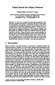
(iii) Loop-Edge: associates a loop 1 with the ordered list of the edges forming i. (iv) Edge-Loop: associates an edge e with the two loops sharing it. (v) Edge-Vertex: associates an edge e with its two extreme vertices. (vi) Vertex-Edge: associate a vertex v with the ordered list of the edges incident on it. It has been proven that the combination of the Face-Loop and Loop-Edge relations is sufficient to describe the boundary of any single-shell solid object in our domain without ambiguities [18]. The SBG is a graph-based description of a generalization of the symmetric data structure proposed by Woo [19] and used as a basic boundary data structure of a modular boundary model [5]. More formally, the SBG of a single-shell object S can be defined as 7-tuple G=(V,E,L,F,FL,LE,EV), where V, E, L and F are the set of nodes of G of type vertex, edge, loop and face, respectively, and FL is the set of the arcs of G joining a node of type face to a node of type loop (face-loop arcs}, LE is the set of the arcs of G joining a node of type loop to a node of type edge (loop-edge arcs}, and EV is the set of the arcs of G joining a node of type edge to a node of type vertex (edge-vertex arcs>. A node of type vertex, edge, loop and face describes a vertex, an edge, a loop and a face of S respectively. Face-loop arcs describe the Face-Loop and Loop-Face relations, loop-edge arcs describe the Loop-Edge and Edge-Loop relations, and edge-vertex arcs the Edge-Vertex and Vertex-Edge relations. The SBG is an undirected graph since we store the symmetric of each encoded relation. If we restrict our consideration to objects with simply-connected faces, the SBG reduces to a graph G'=(V,E,F,FE,EV), where V, E, F and EV have the same meaning as above, and FE is the set of the arcs of G' joining nodes of type face to nodes of type edge. The simplified SBG can be obtained from a general SBG by suitably collapsing arcs of type face-loop and loop-edge and deleting all the nodes of type loop as a consequence. Figure 1 shows an example of simplified SBG.
f3
v~1
~
eI
If4
v£
Figure 1 - a end (*for every I' in L *) end *for every face node *); LABEL CONNECTED COMPONENTS (G, ~ );
LABEL-FACES end. (*FEATURE_EXTRACTION*) In the above description, procedures INSERT_NODE, INSERT_ARC, D E L E T E N O D E and DELETE ARC are used as primitives to manipulate the SBG, while CREATE EMPTY LIST and ADD LIST are primitives for list manipulation. In the algorithm the input SBG G is incrementally modified by deleting loop nodes (from L), inserting new face nodes (corresponding to internal loops), deleting the arcs in FL and LE (face-loop and loop-edge arcs), and creating the new set FE of face_edge arcs. At the end of the external for-loop, G will consist of several connected components, which are computed by procedure LABEL_CONNECTED_COMPONENT5. Finally, the labels of the faces in the various components are transferred to the the list ~ by procedure LABEL_FACES. The worst-case time complexity of the algorithm FEATURE_EXTRACTION is linear in the number of elements (i.e., faces, loops, edges and vertices) of the object S, since each face-loop and loop-edge arc is examined almost twice and the complexity of the connected component algorithm is linear in the number of nodes and arcs of G.
233
4. Features
Identification:
th___eeObject Decomposition Graph
The decomposition of an object S into components describing form features can be represented as a digraph, called the Object Decomposition Graph (ODG). The ODG of an object is a pair D=(M,A), where M is the set of the nodes of D and A the set of its arcs. The nodes of the ODG correspond to the components in ~ , while its arcs describe the inclusion relation between pairs of loops on the connection faces of two abutting components. The ODG is a directed labeled connected multigraph, where every node without predecessor is called a root node. The arcs incident on a node Ci correspond to different internal connection faces, while two or more arcs incident from a component Ci may correspond to a single external connection face. Figure 4 depicts the ODG describing the decomposition of the object of figure 2 into its elementary features (see figure 3).
Figure 4 ODG describing the feature decomposition of the object of figure labels of the arcs are omitted for clarity).
2
(the
The kind of feature described by each component can be unambiguously identified from the ODG. A component Ci which has a single arc incident on it describes a DP-feature, i.e., a depression or a protrusion on a face. Any component Ci such that there are at least two arcs incident on it and all such arcs originate from the same component Cj describes an H-feature attached to Cj, i.e., a through-hole or a handle. If a component Ci has two or more arcs incident on it, which originate from different components, then Ci can describe a through-hole, a handle or a bridge. Similarly to the method described in [4], the feature identification and classification algorithm presented is based only on topological information, i.e., those contained in the SBG and the inclusion relation among the external and the internal loops on the faces. Unlike the method described in [~], it cannot detect protrusions or depressions on edges, but, on the other hand, it can extract a broader class of through-holes and handles. Being based on the extraction of the biconnected and triconnected components, the algorithm in [4] can detect
234
features attached at most to a pair of distinct object faces. Given the 0DG D of S and the boundary graphs [G0,GI,...,Gk} of the components of S, the boundary graph G of S can be unambiguously reconstructed from D by the iterative pairwise merging of adjacent components along their common connection faces. This involves a merging of the components in ~ and the recostruction of the loops on the faces (see [5] for an algorithm for merging a pair of components in a hierarchical boundary model).
5. Concluding R~marks
An algorithm for extracting elementary form features from a relational boundary model of an object, called the Symmetric Boundary Graph, has been described. The symmetric boundary graph is a graph description of the symmetric data structure [19]. Other relational boundary models could be used provided that they encode the face-loop and loop-face relations. The proposed feature extraction method is based on topological information only. Unlike algorithms based on a local geometric approach, it can identify complex compound features which are formed by the combination of through-holes and protrusions or depressions and which do not necessarily have any predefined symmetry. A further advantage of our method is given by the iterative partitioning of the feature extraction problem into independent smaller size subproblems. The algorithm is the first step of a general methodology for recognizing elementary form features according to the classification proposed. A local extraction approach based on geometric information could be applied to the final output of the topological algorithm to identify protrusions and depressions which span two or more faces [6,1!]. The feature extraction process produces an additional graph structure, the Object Decomposition Graph. The representation of a planar-faced object defined by the ODG combined with the symmetric boundary graph description of each component is unique provided that the boundary of the object is initially partitioned into maximal connected faces. It has been shown that the boundary representation of a solid object bounded by compact, orientable, two-manifold surfaces is unique when the object boundary is partitioned into maximal faces [15]. If we apply the decomposition algorithm described in section three to the boundary of a planar-faced object S partitioned into maximal faces, we obtain a unique decomposition of S into components describing features. This is an advantage of the ODG over other modular solid models, like the CSG tree [13], the octree [14] or various hierarchical boundary models [5], which depend either on the sequence of operations used for object design or on the location of the object in the 3D space. The uniqueness of the representation is important in order to decide whether two representations describe the same object. This problem is fundamental in object recognition and also for ensuring the integrity of a data-base of object models in an integrated CAD/C.%M system. Assessing the equality of the topology
of
two
objects
represented
by
235
their boundary requires testing isomorphism of graphs. Two graphs are isomorphic when there exists a bijective mapping between the node sets of the two graphs which preserves adjacencies [8]. The equality of the topology of two objects 5' and 5" described by the combination of their ODGs D' and D" and of the simplified 5BGs of the components of D' and D" can be detected by testing the isomorphism of D' and D" and of pairs of simplified 5BGS Gi' and Gi" corresponding to pair of matched components in D' and D". If every component describes an object with null genus (i.e., homeomorphic to a sphere), then the isomorphism of each pair of components can be tested in polynomial time. In fact, each component can be described by the combination of two graphs, the edge-vertex and the edge-face graphs. The edge-vertex graph of an object S is a graph whose nodes correspond to the vertices of S and arcs to the edges of S [7], whereas in the edge-face graph of S the nodes correspond to the faces and arcs to the edges of S [3,4]. The edge-vertex and the edge-face graphs can be obtained from the simplified SBG by a suitable reduction process. Both the graphs are planar for objects with null genus and are connected for objects with simply-connected faces. Under such assumptions, the isomorphism of two components can be tested by applying isomorphism algorithms for planar graphs to both the edge-vertex and edge-face graph descriptions with a resulting quadratic complexity in the worst case [9,10,16]. If all the arcs in the ODG incident on each component Ci originate from the same component Cj, then the ODG reduces to a labeled tree (with parallel arcs). Hence, in this case, we can detect if the ODGs D' and D" of the two objects to be tested are isomorphic in linear time [2]. If the two trees are not isomorphic, S' and S" are different objects. Otherwise, we have to test the isomorphism of the topology of the two objects by testing the equality of each matched components for every possible isomorphism of D' and D". This process would lead to an algorithm with a time complexity exponential in the height of the two trees. The advantages of using the ODG in testing the isomorphism of two object representations include (i) the possibility of efficiently finding that two representations describe different objects (by applying a sequence of tests based on a set of necessary conditions>, and (ii) the capability of partitioning the isomorphism problem into smaller size subproblems which can be more efficiently handled. Also, several tasks in such an algorithm (like testing the isomorphism of each pair of components once D' and D" have been found to be isomorphic) could be performed in parallel.
References
[i]
Agoston, M., Algebraic Topology, Marcel Dekker, New York, 1976.
[2]
Aho, A.V., Hopcroft, J.E., Ullman, J.D., The Design and Analysis of Computer Algorithms, Addison-Wesley, 1974.
236
[3]
Ansaldi, S., De Floriani, L., Falcidieno, B., Geometric Modeling of Solid Objects by Using a Face Adjacency Graph Representation, Computer Graphics, 19, 3, 1985, pp.131-139.
[4]
De Floriani, L., A Graph-Based Approach to Object Feature Recognition, Proceedings Third ACM Symposium o__nn Computational Geometry, Waterloo, Canada, June 1987, pp.100-109.
[5]
De Floriani, L., Falcidieno, B., A Hierarchical Boundary Model for Solid Object Representation, A.C.M. Transactions o__nnGraphics, 7, i, January 1988.
[6]
Falcidieno, B., Giannini, F., Extraction and Organization of Form Features into a Structured Boundary Model, Proceedings Eurographics'87, September 1987.
[7]
Hanranan, P.M., Creating Volume Models from Edge-Vertex Graphs, Computer Graphics (SIGGRAPH'82), 16, 3, July 1982, pp.77-84.
[8]
Harary, F., Graph Theory, Addison Wesley, Mass., 1969.
[9]
Hopcroft, J.E., Tarjan, R.E., A V**2 Algorithm for Determining Isomorphism of Planar Graphs, Inf. Processing Letters, i, 1971, pp.32-34.
[10]
Hopcroft, J.E., Tarjan, R.E., A V*log(V) Algorithm for Isomorphism of Triconnected Planar Graphs, Journal of Computer and Sistems Science, 7, 1973, pp.323.331.
[11]
Jared, G.E., Shape Features in Geometric Modeling, in Solid Modeling by Computers: from Theory t__ooApplications, edited by M.S. Pickett and J.W. Boyse, Plenum Press, New York, 1984, pp.i21-133.
[12]
Pratt, M., Wilson, P.R., Requirements for Support of Form Features in a Solid Modeling System, Tech. ~ CAM-I, R-85-ASPP-01, June 1985.
[13] Requicha, A.A.G., Representation of Rigid Solids: Theory, and Systems, Computing Surveys, 12, 4, 1981, pp.437-464. [14]
Samet, H., The Quadtree and Related Hierarchical Computing Surveys, 16, 2, 1984, pp.187-260.
Data
[15]
Silva, C., Alternative Definitions of Faces Representations of Solid Objects, Tech. Memo, Automation Project, University of Rochester, 1981.
Methods
Structures,
in Boundary 36, Production
[16] Weinberg, L., A Simple and Efficient Algorithm for Determining Isomorphism of Planar Tryply Connected Graphs, IEEE Trans. on Circuit Theory, CT-13, 2, 1966. [17] Weiler, K., Edge-Based Data Structures for Solid Curved Surface Environment, IEEE Computer Applications, 5, i, 1985, pp.21-40.
Modeling in a Graphics and
237
[18] Weiler, K., Topological Structures for Geometric Modeling, Thesis, Rensselaer Polytechnic Institute, August 1986. [19] WOO, T.C., A Combinatorial Analysis of Schemata, IEEE Computer Graphics and pp.19-24.
Ph.D.
Boundary Data Structure Applications, 5, 3, 1985,