Decoupling Current Control and Maximum Power Point Control in Small Power Network with Photovoltaic Source Mirjana Miloˇsevi´c, G¨oran Andersson EEH Power Systems Laboratory Swiss Federal Institute of Technology (ETH Zurich)
[email protected],
[email protected]
Stevan Grabi´c Faculty of Technical Sciences, Novi Sad, Serbia and Montenegro
[email protected]
Abstract— Often renewable energy sources in distributed generation systems are interfaced with the electric grid through power electronic inverters. The power control, which is usually performed by acting on the system current, is an important issue in power systems. This paper presents a study of two different control methods for voltage source inverter connecting the photovoltaic (PV) cell to the grid. Two methods of decoupled current control are modelled: feedforward and feedback decoupling methods. They have been implemented in dq reference frame. The maximum power point (MPP) tracking method for PV cell based on perturb and observe approach is presented. Case studies for different temperature and irradiance conditions are simulated.
I. I NTRODUCTION Photovoltaic (PV) cells belong to the group of the renewable energy sources that generate dc voltage and current. Therefore, systems containing these cells often require a power electronics interface for power conditioning. The interface usually consists of a converter system converting a dc voltage to an ac voltage of system frequency. PV panels are commonly connected to the grid by a dc-ac inverter connected to a series string of photovoltaic panels, or many small dc-ac inverters which connect one or two PV panels directly to the grid [1]. MPP tracking is used in PV systems in order to achieve the maximum efficiency of the PV cell. In grid connected converters a number of different approaches have been developed and used for MPP tracking. Buck, boost, buck-boost, etc. converters are considered as possible dc-dc converter that can connect PV cells to the dc-ac grid inverter. Buck and boost converters show the best efficiency for a given cost [2]. The boost converter is shown to have a slight advantage over the buck converter at low light levels, since it can always track the MPP [3]. The current control is an important issue in power electronic circuits. Three major classes of regulators have been developed over last few decades: hysteresis regulators, linear PI regulators and predictive dead-beat regulators [4]. Although high performance control strategies have been proposed, they still exhibit coupling problems not providing the decoupling of the active and reactive current components (not allowing
the independent control of the active and reactive power) [5]. A short review of the available current control techniques for the three phase system is given in [6]. In this paper, models and simulation of the PV cell and its MPP tracking are presented. The VSI current decoupling control methods (feedforward and feedback) are implemented in the rotating (synchronous) dq reference frame since the synchronous frame controller can eliminate steady state error and has fast response by decoupling control. The rest of the paper is organized as follows - the system description is given in Section II. The MPP tracking method is explained in Section III. The decoupling methods for active and reactive current control are described in Section IV. The simulation results are presented in Section V, followed by conclusion in Section VI. II. S YSTEM D ESCRIPTION A schematic overview of the power system with PV cell source is given in Fig. 1. This system consists of a PV cell and boost converter that is used for controlling the MPP. The VSI is used for transforming the dc current into ac current of system frequency, as well as for the active and reactive power control in the system. PV cell
Fig. 1.
Boost Converter
C
Voltage Source Inverter
Power Network
Schematic presentation of the system with PV cell
A. PV Cell Modelling The mathematical description of the physical processes in a PV cell are given in [7]. The equivalent circuit of a PV cell is given in Fig. 2. The current source Ip is light induced current. This current is directly proportional to the irradiance. The diode represents the p-n junction of the solar cell. The resistance Rs is the series resistance that gives a more accurate shape between the MPP and the open circuit voltage. The shunt resistance in parallel
Rs
I
B. Model of the Boost Converter In order to be able to track the MPP to achieve the maximum efficiency of the PV cell the dc-dc converter is needed. In this paper, boost converter is used since it has the best efficiency for significant step up [3]. Model of the boost converter is given in Fig. 3.
Id
Upv
Ud
Ip
Fig. 2.
Model of solar cell
with the diode can be neglected since it has a big value and has no influence for current calculation. The mathematical equations that describe the model of the PV cell are given by: q(Upv + IRs ) ) − 1) (1) nkT where q is charge of one electron, n is diode quality factor, k is Bolzman’s constant and current Ip is defined with: I = Ip − I0 (exp(
Ip = Ip (T1 )(1 + K0 (T − T1 ))
(2)
Ip (T1 ) is proportional both to the short circuit current at temperature T1 and to the ratio between the irradiance at temperature T1 and the nominal irradiance : Ip (T1 ) =
G Gnom
Isc (T1 )
(3)
K0 is the coefficient that represents the dependance between the temperatures T1 and T2 , and is given by: K0 =
Isc (T2 ) − Isc (T1 ) (T2 − T1 )Isc (T1 )
(4)
Current I0 in (1) can be calculated for any temperature using the following equation: I0 = I0 (T1 )(
qUg 1 T 3 1 ( − )) ) n exp(− T1 nk T T1
(5)
where Ug is band gap voltage and current I0 (T1 ) is: I0 (T1 ) = Isc (T1 )/(exp(
qUoc (T1 ) ) − 1) nkT1
(6)
Series resistance Rs is given by: Rs = −
dU 1 − dIUoc Xv
(7)
(8)
Using (1), the PV cell voltage can be calculated as: Upv =
Ip − I nkT ln(1 + ) q I0
D
R
Upv
T
Fig. 3.
(9)
Equation (9) represents the mathematical model of the PV cell used in this paper.
C
Udc
Model of boost converter
The input voltage of the boost converter is Upv since this voltage is actually the output voltage of the PV cell. The output voltage of the boost converter is denoted as Udc since this voltage is the voltage of the DC link connecting the boost converter to the grid inverter. Mathematical model of the boost converter is given with two different states. The first state is when transistor is turned on: diL − RiL − Ut = 0 dt From (10) the inductance current is given by: Upv − L
1 diL = (Upv − RiL − Ut ) dt L The second state is when transistor is turned off: diL − RiL − UD − Udc = 0 dt From (12) the inductance current is given by: Upv − L
(10)
(11)
(12)
1 diL = (Upv − RiL − UD − Udc ) (13) dt L The average model of the boost converter can be calculated using the fact that in steady state the sum of the currents when transistor is turned on and off is zero: ∆iL(T on) + ∆iL(T of f ) = 0
and Xv is given as: qUoc (T1 ) q exp( ) Xv = I0 (T1 ) nkT1 nkT1
iL
L
(14)
When transistor is turned on, the following approximation is used: ∆iL(T on) diL = (15) dt DT where T is a period and D is a duty ratio while transistor is on. Using (11) and (15) we have: Upv − RiL − UT (16) L Similarly, when transistor is turned off, the following approximation is used: ∆iL(T on) = DT
∆iL(T of f ) diL = dt (1 − D)T
(17)
Using (13) and (17) we have: Upv − RiL − UD − Udc (18) L Applying (16) and (18) to (14), the output voltage of the boost converter is given by:
Since the boost converter is used for the MPP tracking, voltage decrease is done by incrementing the duty ratio D, and vice versa, when there is a need to decrease voltage, the boost duty ratio D is decremented. There are four possible situations for controlling the boost converter in order to ensure the MPP tracking:
∆iL(T of f ) = (1 − D)T
Upv − RiL − UD + DUD − DUT (19) 1−D If we neglect RS , UD and UT , the average model of the average output voltage of the boost converter is given with: Udc =
Upv 1−D III. M AXIMUM P OWER P OINT T RACKING Udc =
(20)
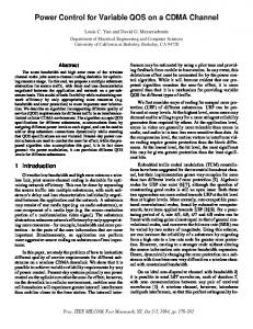
MPP tracking is the technique that ensures that the PV cell under any change in irradiance level and the cell temperature conditions gives the maximum available power. In other words, there is a need to track the MPP in order to maximize the power delivered to the load from the PV cell under any circumstance that causes the output voltage of the power system to lose regulation. By controlling the boost converter which is connected to the PV cell is possible to track the MPP. There are different control methods for the MPP tracking [8],[9]. In this paper, the perturb and observe method is implemented due to its ease of implementation. The perturb and observe method is based on the constant measuring of the PV current and voltage and calculation of its power output while the working point is moving in order to reach the maximum power. This algorithm has two parameters: 1) the time interval between the time when measuring is done and the time when the working point moves from its optimal value and 2) the increment of the movement of the working point itself. The MPP tracking method is depicted in Fig.4. It can be dP seen that at the MPP it is dU = 0. There are 5 possible movements of the working point. For positions 1 and 2, the dP derivative dU has a positive value and there is a need to increase the voltage to reach the MPP. In other hand, positions 3 and 4 have negative derivatives and there is a need to decrease the voltage.
1. 2. 3. 4.
dU (k) > 0 dU (k) < 0 dU (k) > 0 dU (k) < 0
and and and and
dP (k) > 0 dP (k) < 0 dP (k) < 0 dP (k) > 0
2
P [W]
IV. D ECOUPLING M ETHODS FOR ACTIVE AND R EACTIVE C URRENT C ONTROL In this paper we applied two decoupling methods: feedforward and feedback decoupling method for current control of the VSI in rotating dq frame. A. Model of the Three Phase Inverter The power circuit of the three-phase voltage source inverter (VSI) is shown in figure 5. idc Sa
dP >0 dU
5
3
dP