This paper aims to present some of the main features of the Workflow Description Language (WorDeL) and demonstrate their usage in defining Earth Data ...
ISPRS Annals of the Photogrammetry, Remote Sensing and Spatial Information Sciences, Volume III-4, 2016 XXIII ISPRS Congress, 12–19 July 2016, Prague, Czech Republic
DEFINING EARTH DATA BATCH PROCESSING TASKS BY MEANS OF A FLEXIBLE WORKFLOW DESCRIPTION LANGUAGE Constantin Nandra ∗, Dorian Gorgan Computer Science Department, Technical University of Cluj-Napoca, Cluj-Napoca, Romania - (constantin.nandra, dorian.gorgan)@cs.utcluj.ro
KEY WORDS: workflow description language, earth data, batch processing, processing workflow
ABSTRACT: This paper aims to present some of the main features of the Workflow Description Language (WorDeL) and demonstrate their usage in defining Earth Data processing tasks. This description language is based on the flexible description of processing tasks as workflows, composed of basic processing operators. This approach allows the language to offer an intuitive way of representing processing tasks, without requiring programming expertise from its users. It also allows its users to employ and integrate existing functionality into their design, thereby reducing the design complexity and development effort of newly defined processing workflows. WorDeL supports the transparent adaptive parallelization of the processing tasks over high performance computation architectures, such as cloud-based solutions. Throughout the paper, we will exemplify this language’s use in creating flexible, reusable and easy-to-understand earth data processing descriptions, with an emphasis on satellite image processing.
1. INTRODUCTION The ability to store and manage data has always been a defining characteristic of human civilization, reflecting its level of sophistication. Keeping records has been instrumental in the establishment of any form of social organization, from the early citystates, to kingdoms, nations and the first commercial entities. While society’s data management capabilities have been steadily increasing over the last centuries, the era of the computer and the internet has really sparked off a revolution in terms of size of the raw data produced and processed around the globe. According to some estimates (Hilbert and Lopez, 2011), the total amount of data stored globally had reached 2.9x1020 bytes as of 2007, following a twenty-year growth period of 23% per year. A more recent estimate (Murdoch, 2012) places the quantity of globally stored data at approximately 2.8x1021 bytes - 2.8 zetabytes - as of 2012, a tenfold increase since 2007. According to the same source, out of these data only about 3% had any kind of useful tags associated, making them usable, and barely 0.5% were actually being analyzed. This goes to highlight a trend of data acquisition rates overtaking the available processing capabilities. The term Big Data has been steadily gaining popularity over the last years due to the abundance of raw data in many different fields, from astronomy and earth observation to finance and the retail industry. Although the term is usually implicitly associated to the problem of managing very large quantities of data, it should be noted that the concept of Big Data has a somewhat broader definition, as it is concerned with a number of problematic characteristics of modern data sets (Gartner, 2011):
• Volume - perhaps the most intuitive characteristic, this has to do with the actual size of the data sets; • Variety - this refers to the multitude of data sources and heterogeneous data types; ∗ Constantin
Nandra
• Velocity - this characteristic refers to both the rate at which new data is gathered and the rate at which the available data can be processed; The problem of Big Data is prevalent in many fields of study, one important category being those dealing with Earth Observation EO - data. The main issues, in this case, are the volume and velocity, seeing as most often we are talking about raster image data captured by an increasing number of aerial and space-borne sensors. Thus, the sheer volume and acquisition rates may threaten to overwhelm many organizational storage capabilities, leading to situations in which data value is overtaken by storage costs, which will, in turn, lead to the loss of aging data. Within the BigEarth project (BigEarth, 2014), we are trying to offer solutions for increasing the efficiency of the data processing efforts. In order to achieve this, we are focused on a twopronged approach. On one hand, we are experimenting with a high-performance, cloud-based computing solution in order to shorten the overall process execution time. On the other hand, we intend to provide a highly flexible method of specifying the data processing tasks, in order to improve the description process. In the case of this paper, the focus is on a workflow based approach, which is meant to increase the modularity of the design and, as a consequence, promote reusability. As a means of specifying the structure of the workflow we have decided to use a specially designed description language called WorDeL - Workflow Description Language. This language is meant to offer the user - EO data specialist - an intuitive, flexible and effective way of creating, re-using and integrating workflow descriptions of data processing tasks. Throughout this paper we will present the main concepts of the WorDeL language, highlighting and exemplifying their use in defining earth data processing tasks. The paper is structured as follows. Section 2 will briefly present a series of languages used for describing process descriptions over various types of data. In Section 3, we are going to highlight the overall function and usage of the WorDeL language, followed by
This contribution has been peer-reviewed. The double-blind peer-review was conducted on the basis of the full paper. doi:10.5194/isprsannals-III-4-59-2016
59
ISPRS Annals of the Photogrammetry, Remote Sensing and Spatial Information Sciences, Volume III-4, 2016 XXIII ISPRS Congress, 12–19 July 2016, Prague, Czech Republic
a brief description of its main elements, in Section 4. Throughout Section 5 we will present a couple of examples in which we employ WorDeL for the purpose of defining satellite image batch processing tasks, highlighting its features and explaining their usage. The last section will contain our concluding remarks with regards to WorDeL and its role within our system.
Pigeon (Eldawy and Mokbel, 2014) is an interesting approach to using Hadoop (Hadoop, 2015) for the purpose of processing EO data. It is intended as an extension for the Pig Latin language (Pig, 2012), which allows users to define MapReduce programs for spatial data. Pigeon is implemented with user-defined functions, which are a Pig feature allowing users to specify custom processing tasks using languages such as Java, Python, and JavaScript.
2. RELATED WORKS The processing of EO data is invariably tied to the use of geographical information systems - GIS - which, by definition, refer to any information system capable of performing operations like editing, analyzing, visualizing or in any way manipulating geographical data (Clarke, 1986). Nowadays there are a plethora of GIS solutions allowing users to manage and process a variety of data types and formats. GRASS GIS (GRASS, 2015) is an open-source solution with a modular architecture, consisting of over 350 modules, which offers many features and capabilities, like processing and manipulating both raster and vector data, rendering maps and analyzing multispectral images, among many others. ArcGIS (ArcGIS, 2015) is a tool which brings the processing of geographical data to the cloud. It is also notable that it provides a collection of integrated components, usable from both desktop computers and portable devices. Another interesting development, QGIS (QGIS, 2015) comes as a cross-platform open-source system, which builds upon a host of other open-source solution such as GRASS and PostGIS (PostGIS, 2015). When it comes to specifying the data processing tasks, most modern GIS solutions employ some form of graphical user interface GUI. While they may prove intuitive to most users, GUIs can also become cluttered in the case of complex systems, increasing the user training time. Therefore, some systems also offer the option of specifying the processing tasks using some form of description language. As a prime example, GRASS GIS was originally intended to allow users to interact with it via Unix shell commands and scripts. In this case, the user would invoke the functional modules provided, and prepare their execution using such commands. This approach, however, may prove quite problematic for users unaccustomed to UNIX-style commands. In (Choi, 2014), the authors propose the usage of a domain specific language - DSL - to describe the processing of high volume and high throughput telescope and microscope data. The language, called Vivaldi, has a Python-like syntax and can be used for distributing the data processing tasks on heterogeneous computing architectures. (Kramer and Senner, 2015) suggests the usage of a DSL for specifying big data processing workflows, in an approach similar to our own. Once the workflow is parsed, a series of executable jobs are determined, all of which are then sent for execution to a cloud system. Diderot (Chiw et al., 2012) is another domain specific language, designed for processing and analyzing biomedical images. This language has a C-like syntax and was created in order to manage large processing tasks which can be decomposed into many, smaller, independent sub-computations. This way, it can take advantage of the inherent computation parallelism in order to improve the process execution performance.
Another category of description languages used to describe processing workflows is represented by the XML-based solutions used for the definition of web service aggregates. (Leyman and Roller, 2002) shows the use of BPEL4WS in defining, what are called, business processes. In this particular case, there is a need to link together self-contained functional units, represented by web services, in order to form larger, more complex processes. For this scenario, XML-based solution are quite useful, since linking web services entities requires a lot of information - like address, port, method of access and so on - which is included in the description. Similar to BPEL4WS, MOML (Lee and Neuendorffer, 2000) Modeling Markup Language is another interesting XML-based description language. Unlike the former, however, this one does not make any assumptions whatsoever about the nature of the interlinked entities, or even the meaning of the relationships between them. Essentially, MOML provides an abstract way of defining relationships between entities. For this reason, it comes as a highly customizable solution, with features like the possibility of defining classes of entities and relationships, and even extending and building upon existing definitions. MOML is used within the Ptolemy project (Ptolemy, 2014) an ongoing UC Berkeley research project which aims to model and simulate the behavior of concurrent, real-time systems - and served as the main inspiration for our work in the development of WorDeL as a workflow definition language. In our case, we wanted to create a language specialized on allowing users to connect operators, so we opted in favor of a more compact, less verbose, non-XML approach. A major development consideration, in our case, was that of keeping the description as humanreadable as possible, encapsulating any extra information within the entities. This is derived from our need to create a language that could allow users without programming experience - which could be at a disadvantage when dealing with languages such as Python or shell scripts - to easily define processing descriptions. 3. THE PROPOSED SOLUTION 3.1
BigEarth platform
Our solution for the description of data processing tasks is an essential part of the BigEarth project (BigEarth, 2014), wherein we are trying to improve the overall efficiency of Earth Data processing by combining flexible description methods with high performance, cloud-based computing architectures as execution environments. As seen in Figure 1, the overall architecture of the system is based upon three essential components. These also dictate the actual execution flow of a user-specified process. First, the user submits the description of the processing task, together with the data it is to be applied on, to the system. The Parser processes the description files, generating a workflow representation which is then made available for use by the Scheduler. This component, using the data and the workflow representation
This contribution has been peer-reviewed. The double-blind peer-review was conducted on the basis of the full paper. doi:10.5194/isprsannals-III-4-59-2016
60
ISPRS Annals of the Photogrammetry, Remote Sensing and Spatial Information Sciences, Volume III-4, 2016 XXIII ISPRS Congress, 12–19 July 2016, Prague, Czech Republic
starts determining the atomic executable tasks which make up the user-defined workflow. The atomic tasks generated by this component, also known as commands, are then sent to the Executor component, which has at its disposal a pool of processing resources that it will use in order to effectively distribute and process these tasks.
Understanding the format of this example instruction can help the user grasp the representation model employed by WorDeL, as a processing description consists mainly of a list of such instantiation operations. Generally, such an operation has the following format: [in params] OP N AM E : instance name [out params] It is important to note that the parameters are just names given by the user to keep track of the connections between different operators. As for the connections, they are inferred by the parser, based on the correspondence between the parameter names. Figure 2 illustrates an example of just how such a connection might be formed.
Figure 1. BigEarth platform processing chain
3.2
WorDeL (Workflow Description Language)
Our system is built around the concept of a workflow being used in order to describe virtually any kind of processing algorithm. In this approach, the user needs no programming experience whatsoever, instead relying on a set of already implemented, of-theshelf operators to do the processing.
Generally, when talking about connections formed between two operators, they form when one operator’s output parameter matches one of the inputs of the other. In this case, the output of ’inst1’ ’sum’ - is also used as the input of ’inst2’. As one can see in the figure, we also provide a viewer tool, in order to help the user keep track of the workflow state and visualize its content - operators and connections. The viewer tool, coupled with a mechanism for error detection, can greatly help users debug any connection errors which might appear during the design of a processing description.
In order to facilitate the act of defining big data processing tasks we designed and implemented an easy-to-use description language which is intended to provide a simple and flexible way of linking together existing operators into processing workflows. WorDeL allows the user to define workflows using basic units of functionality. These are called operators and are, in essence, executable programs onto themselves. They can have any form, from shell scripts to ’.exe’ or ’.jar’ files, the only requirement being that they should have at least one input and one output, both supplied via file names. By incorporating the functionality enclosed within an operator, we intend to increase design reusability and modularity. These are some of the most important aspects of WorDeL, and centerpieces of its flexibility. The possibility of re-using and re-integrating existing processing descriptions into new designs allows the user to supplement and personalize the default operator library to fit specific needs and requirements. 4. MAIN CONCEPTS OF WORDEL 4.1
Operator
As mentioned before, WorDeL uses the concept of the operator as a self-sufficient functional unit in order to create processing workflows of ever-increasing scope and complexity. In WorDeL, each operator has an interface, which is a collection of input and output ports. Each port has a name and a type, representing an argument of the operator. The user has access to a list of operator specifications - including name, number and type of parameters (ports) - which can be consulted when trying to make use of them. The employment of the operators inside a new process description - also known as operator instantiation - requires the user to specify the name of the operator, along with a list of arguments to match its input and output ports. The example below shows the instantiation of the operator named ’SUM’, requiring two input parameters and one output. [variable1, variable2] SU M : instance [sumResult]
Figure 2. Connection example
4.2
Workflow
This is another central concept of WorDeL, since it represents the processing algorithm defined by the user. What’s more, because of its properties, it allows for design modularity and component reuse. In WorDeL, a workflow - also referred to as flow - is very similar to an operator, so much so that a user can employ them interchangeably. Just like an operator, a workflow has an interface, made up of input and output ports - Figure 2. Because of this, it can be instantiated inside other workflows, allowing the user to build upon already existing processing descriptions. The workflow structure, as seen in Figure 2, is defined by a list of operator instances and the connections formed between them and the workflow’s ports. 4.3
Process
This is what may be called the actual business end of the language, as it allows the user to launch into execution any existing processing description.
This contribution has been peer-reviewed. The double-blind peer-review was conducted on the basis of the full paper. doi:10.5194/isprsannals-III-4-59-2016
61
ISPRS Annals of the Photogrammetry, Remote Sensing and Spatial Information Sciences, Volume III-4, 2016 XXIII ISPRS Congress, 12–19 July 2016, Prague, Czech Republic
In order to execute a given processing, one must supply both the processing description - in the form of a workflow - and the input data. The ’process’ element provides the mechanism for this.
be the type of the values contained within - like in the example below: List < Integer >
Figure 3 shows a process example. In this case, the process is reliant on the workflow description from Figure 2. In order for the process to be able to use the ’test’ workflow - which it instantiates - it has to point to its actual location - in this case, the file ’test.wdl’.
Similarly, a tuple is declared using the ’Tuple’ keyword and the collection of contained types. The example below defines a custom tuple type which contains four values - two integers, a float and a string. Keep in mind, however, that the order of the parameters matters.
We strongly encourage the practice of defining workflows and processes within separate files in order to better organize one’s design. By keeping the workflow descriptions and the data they are to be associated with into separate files, one can more easily reuse and integrate the workflow description into more complex designs, or employ them in multiple, different processes without having them tied to a specific data set.
T uple(Integer, String, F loat, Integer) The composite types allow the user to define custom types to suit virtually any necessity. That being said, complex, recursive definitions are also possible - like in the example below. This kind of flexibility allows the user to create objects by aggregating together different values. T uple(List < Integer >, String, T uple(String, F loat))
Another aspect of note is that launching tasks into execution is actually done by instantiating workflows (and even operators). Notice in the figure that the process only contains the instance of the test workflow.
This typing mechanism could be used in image processing for specifying various data structures which might be needed by the defined workflow. For example, one could define a list of image regions like this: List < List < T uple(F loat, F loat) >> In this example, the inner tuple defines a two-dimensional point with x and y coordinates and the inner list is a list of points interpreted as a closed region.
Figure 3. Process example
One should note, however, that there is a difference in instantiating operators/workflows inside a workflow definition and doing so inside a process. When inside a workflow definition, one should use the parameters of the instances to define connections, in which case the actual parameters are formal and only need to match in terms of name and type. On the other hand, when inside a process, instances must receive as parameters the actual values intended for the execution of the algorithm instantiated. This is exemplified in Figure 3, line 5. 4.4
4.5
For-Each replication mechanism
There may be cases in which the user wants to run a given workflow or operator on multiple input data sets. This would normally require the user to create a number of different processes - one for each data set - and run them one at a time. This would result in time lost by the user defining each individual process and time lost by the system having to wait for the user’s input. The ’for-each’ mechanism aims to solve this problem by giving the user the possibility to specify the workflow and the input data set, allowing the system to generate the processing tasks dynamically, according to the number of items in the data set. The overall structure of this construct is the following:
Data Types [in list1 : i1, in list2 : i2, ... ]f or − each[out list1 : o1, ... ]
In order for the user to employ operators properly, WorDeL enforces a system of data types. This system is used inside a workflow definition in order to validate the connections between operators. It is also useful when defining processes, since it allows the user to specify the input values. In WorDeL, there are five basic types: Integer, Float, String, Boolean and File, as well as two composite types: List and Tuple. Although the operators share data exclusively through files, assigning custom types to their ports offers a formal way of ensuring the compatibility of the specified connections. It also provides a means of verifying the content of the intermediate files associated to the connections. However, the main advantage in having this type system is that it gives the user the possibility of specifying the values directly inside the process definition - as seen in Figure 3. The two composite types allow the user to create custom value aggregates. The list is a homogeneous collection - containing any number of values of the same type - while a tuple may contain any number and any combination of values. A list type is declared using the keyword ’List’ and assigning a sub-type, which will
< sub − workf low > end At first look, this construct retains the basic syntactic form of an operator instance. The first difference can be seen in the input and output parameters. This construct is heavily reliant on lists, which it uses for the definition of the input and output data ports. These lists hold both the input value pairs and the outputs to be generated. Each parameter in the input and output lists is a pair having the format: list name : item name This is done in order to refer to each individual element of the input and output lists when defining the inner workflow. The lists are supplied from the outside of the construct, while the items are only visible inside, so that they can be accessible to the internal workflow. The inner workflow is actually just a series of instantiated operators. There is a major restriction when defining the inner workflow. WorDeL treats this inner workflow as if it were completely
This contribution has been peer-reviewed. The double-blind peer-review was conducted on the basis of the full paper. doi:10.5194/isprsannals-III-4-59-2016
62
ISPRS Annals of the Photogrammetry, Remote Sensing and Spatial Information Sciences, Volume III-4, 2016 XXIII ISPRS Congress, 12–19 July 2016, Prague, Czech Republic
isolated from the outside. Therefore, its operators can only connect to the ’for-each’ construct’s input and output parameters or among themselves. In other words, elements inside the ’for-each’ construct cannot be linked to elements outside. This construct actually generates instances of the contained workflow for each input-output pair in its provided lists. It goes without saying that those lists should have the same length, or else the workflow cannot be instantiated. The ’for-each’ language feature offers the user two major benefits. First of all, and perhaps the most obvious, is the ability of applying different input sets to an existing workflow, without the need of specifying a new process for each such occasion. This can speed-up the procedure of running different data sets through the processing workflow defined by the user. Another, more subtle, advantage is the fact that this approach can break down a processing task into several, smaller, independent and parallel processes which can then be executed on a multi-core computing architecture, which could drastically reduce the overall run time of the process. 5. EXPERIMENTS AND VALIDATION
Figure 4. For-each workflow example
Figure 5 shows the structure of the workflow described in Figure 4. The top side represents the structure of the ’repeatNDVI’ workflow, while the bottom side shows the structure of the inner workflow, defined within the ’for-each’ structure. Notice how ’nirSet’ and ’redSet’ are the inputs interfacing with the actual worklow, while ’nirImage’ and ’redImage’ provide the input interface for the inner workflow.
Throughout this section we will exemplify the usage of our description language for defining earth data processing tasks. To this extent, we will provide a couple of examples, presenting the WorDeL syntax and showing the results of the processing execution. 5.1
Simple For-Each example
The first example is intended to show the usage of a simple ’foreach’ structure in generating a series of processing commands. These consist of a single NDVI - Normalized Difference Vegetation Index - operator applied on a set of input image data. The NDVI is used as a simple graphical indicator for the presence of live, green vegetation. It was first formulated in (Kriegler et al., 1969) and employed by (Rouse et al., 1974) in a study of the Great Plains region of the central United States. The NDVI formula is the following: N DV I =
(N IR − RED) (N IR + RED)
(1)
In the formula, the NIR and RED inputs represent the near infrared and red spectral bands of an image. In the example seen in Figure 4 we describe a simple workflow which operates on two lists of input files - containing NIR and RED band images. This workflow employs a ’for-each’ construct in order to apply the NDVI operator on successive pairs of the input images. As seen on lines 3 and 4, the workflow has two inputs - lists of files containing the two spectral bands - and an output. This is also in the form of a file list, representing the list of NDVI images resulted from applying the operator on pairs of input data taken from the two input lists. The workflow consists of a single ’foreach’ element which, in turn, is made up of one NDVI operator instance. Notice on lines 6 and 7 how the iteration mechanism is used. ’nirImage’ and ’redImage’ are employed in order to refer to the elements of the two input lists while inside the ’for-each’ structure. They also represent the input ports of the internal workflow created within the ’for-each’ element. In other words, one cannot link nodes inside the ’for-each’ structure with nodes from the outside; each set of instances inside the structure forms a local, independent workflow which is linked to the outside via the input and output parameters of the ’for-each’ structure.
Figure 5. For-each workflow structure
Figure 6 shows the executable commands generated by the Scheduler component after applying the inputs to the workflow representation, which was obtained from the Parser component. The outcome consists of three executable commands, each able to launch into execution the operator - represented by ’NDVI.sh’ - with three different sets of input data. In this case we employ some of the operators made available by the GRASS GIS library and incorporate them into shell scripts, which act as wrappers exposing a simple, file-based interface. It should be noted that the operators can come in any conceivable form, from shell or python scripts, to normal executable programs, as long as their functionality can be accessed in a uniform, file-based manner. 5.2
Compound For-Each example
The second example builds upon the first one and demonstrates the use of one ’for-each’ structure within another. We started with the NDVI operator applied on an input image, and envisaged a scenario where the user might want to apply this operator on a set - or list - of image regions. The regions are defined as rectangular areas, delimited by four floating-point values. The basic processing algorithm would consist of: clipping the images against a given region, applying the NDVI operator on the result and executing a pseudo-coloring operation on the image in order to make it more relevant to the user.
This contribution has been peer-reviewed. The double-blind peer-review was conducted on the basis of the full paper. doi:10.5194/isprsannals-III-4-59-2016
63
ISPRS Annals of the Photogrammetry, Remote Sensing and Spatial Information Sciences, Volume III-4, 2016 XXIII ISPRS Congress, 12–19 July 2016, Prague, Czech Republic
Figure 6. For-each scheduling results
Figure 7. Double for-each scheduling results
In order to do this, one would need a something like the ’fragment NDVI’ workflow - shown in Figure 8(a). This workflow is similar to the one from the previous example. There is, however, one major difference. Instead of iterating on a set of images, the ’for-each’ structure in this case uses the same image data - ’imgNIR’ and ’imgRED’ - for all iterations. The only thing that changes over the iterations is the fragment definition. The fact that the same image is used within multiple iterations, is specified by employing the notations ’imgNIR:imgNIR’ and ’imgRED:imgRED’ - seen on line 6. By using the same name for the collection and for the iterating instance, the user tells the system that there should be no iteration on that particular input. The result is that this workflow operates on a single image - represented by the two image bands - clipping it against different regions and applying the NDVI operator on each of the resulting fragments. The next step was to take this workflow and execute it repeatedly for a set of images. Since ’fragment NDVI’ requires two image bands and a list of regions as input data, it follows that our new, larger workflow would require two input lists of image files - one list for NIR-band images and one for RED-band images - as well as a number of region lists, one list for each NIR-RED image pair. This workflow’s description can be seen in Figure 8(b). The first thing to notice in the definition of the ’image List NDVI’ workflow is the usage of the ’include’ statement. This is necessary in order to access the ’fragment NDVI’ workflow, which is in a separate file - ’fragment NDVI.wdl’. Of course, one could easily have defined both ’for-each’ structures within the same file. However, defining part of the functionality inside another file has the double advantage of making the code more readable and increasing the modularity of design. Once defined as an independent piece of functionality, ’fragment NDVI’ can subsequently be employed in any number of designs, saving time and reducing the complexity of the description. Apart from the two lists used to specify the collections of image bands, one can notice the input ’fragmentLists’, which is a list of file lists. Each file contains the specification of a rectangular
region. A list of such files is associated to a given image, therefore, for a set of images, multiple region lists are required. The workflow has one output, which is also a list containing lists of files. This is because each image and its associated regions will produce a list of NDVI-ed regions. As for the body of the workflow, it only consists of a ’for-each’ structure which will dynamically instantiate the ’fragment NDVI’ workflow for each image band set and associated fragment list. As seen on line 8, this time, the ’for-each’ structure will iterate on all of its inputs. The instance elements of the input lists specified on line 8 serve as the inputs of the instantiated operator within the ’for-each’ structure. Workflow description aside, one of the most interesting elements in this example is represented by the process ’p1’ - responsible for the execution of the workflow. As mentioned before, the operator instantiation within a workflow is different from that done within a process. When creating an instance within a process, one must always provide the actual values, the data with which the processing description should be executed. Another thing to note is the fact that while inside a process, only one operator or workflow can be instantiated. If there is a need to link up different operators, the user is encouraged to do so within another workflow and instantiate it afterwards. This measure has the benefit of forcing a clear demarcation between the processing description and the data its needs to process, thus increasing the overall modularity of design. Another aspect of note within this example is the mechanism for specifying the input values to the process. On the one hand, we employ the ’fromDirectory’ directive in order to automatically create a list of all the files within the directory given as argument. This is useful for situations in which the number of list elements is too large for the user to manually input. The second method, a more direct approach, relies on the user to specify the contents of the list within the process definition. Figure 7 shows the partial result of the scheduling process for this example scenario. The figure shows the database listing of
This contribution has been peer-reviewed. The double-blind peer-review was conducted on the basis of the full paper. doi:10.5194/isprsannals-III-4-59-2016
64
ISPRS Annals of the Photogrammetry, Remote Sensing and Spatial Information Sciences, Volume III-4, 2016 XXIII ISPRS Congress, 12–19 July 2016, Prague, Czech Republic
Figure 9. For-each processing results
the generated commands. In this case we only listed about half of the table, due to space limitations, but this is enough to get a grasp of the overall effect. As seen in the figure, there are a total of 12 rows containing generated commands. The first eight represent the result of the first iteration of the outer ’for-each’ element. Each iteration of the inner ’for-each’ generates four commands: two used for clipping the image bands against a given region, the third applying NDVI and a fourth one doing a pseudo-coloring on the resulted image. Figure 7 lists the result of three such iterations, highlighting the result files. One can notice that the first two iterations make up one iteration of the outer ’for-each’. As seen in Figure 8(b), this iteration works with the first set of image bands - ’i1RED’ and ’i1NIR’ - and the first fragment list - {‘f1‘,‘f2‘}. As a result, this outer ’for-each’ iteration produces two output files: ’resultImage0’ and ’resultImage1’. These two form the first output list. The last four commands are part of the second iteration of the outer ’for-each’ structure and generate the first element of the second output list: ’resultImage10’.
Figure 8. Double for-each example
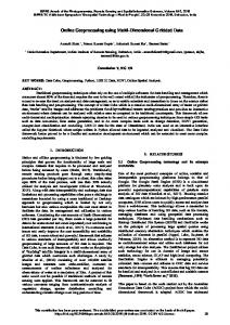
As for the input of this example, we used Landsat satellite image data taken from the repository made available by the Global Land Cover Facility from the University of Maryland (GLCF, 2014). The processing was done on three images, and a total of six randomly defined regions. We selected three images, found in the sets ’WRS2/p017/r021’ through to ’WRS2/p017/r023’ ’GLS2010’. We used band number 3 for RED and band number 4 for NIR. Figure 9 shows the resulting pseudo-colored NDVI regions, along with their positioning within the original images NIR band - and the color table used for the NDVI values.
This contribution has been peer-reviewed. The double-blind peer-review was conducted on the basis of the full paper. doi:10.5194/isprsannals-III-4-59-2016
65
ISPRS Annals of the Photogrammetry, Remote Sensing and Spatial Information Sciences, Volume III-4, 2016 XXIII ISPRS Congress, 12–19 July 2016, Prague, Czech Republic
An important aspect to note is the fact that all these generated sets of commands are actually independent and all six processing instances resulted from this example could be executed in parallel, given enough resources. This is one of the main benefits of employing the ’for-each’ construct, making it suitable for defining repetitive, compute-intensive, batch processing tasks. CONCLUSIONS When talking about Big Data, the most challenging aspect lays in processing them in order to gain new insight, find new patterns and gain knowledge from them. This problem is likely most apparent in the case of Earth Observation data. With ever higher numbers of data sources and increasing data acquisition rates, dealing with EO data is, indeed, a challenge in itself. To answer this trend, the BigEarth project (BigEarth, 2014) aims to combine the advantages of high performance computing solutions with flexible processing description methodologies, in order to reduce both task execution times and task definition time and effort. As a component of the BigEarth platform, WorDeL is intended to offer a flexible, compact and modular approach for the user to employ in the task definition process. WorDeL, unlike other description alternatives such as Python or shell scripts, is oriented towards the description of topologies, using them as abstractions for the earth data processing algorithms. This feature is intended to make it an attractive alternative for users lacking in programming expertise. By promoting a modular design, WorDeL not only makes the processing descriptions more user-readable and intuitive, but also helps organizing the processing tasks into independent sub-tasks, which can be executed in parallel on multi-processor platforms, in order to improve execution performance. As a platform component, WorDeL represents the means by which the user interacts with the system, describing processing algorithms in terms of existing operators and workflows, which are ultimately translated into sets of executable commands. As shown in the previous examples, WorDeL was designed to help in the definition of compute-intensive batch tasks, which can be distributed and executed on high-performance cloud or grid-based architectures, in order to improve the processing time and ultimately increase the effectiveness of EO data analysis methods. ACKNOWLEDGEMENTS
BigEarth, 2014. Bigearth project - flexible processing of big earth data over high performance computing architectures. Chiw, C., Kindlmann, G., Reppy, J., Samuels, L. and Seltzer, N., 2012. Diderot: A parallel dsl for image analysis and visualization. Proceedings of the 33rd ACM SIGPLAN Conference on Programming Language Design and Implementation 47(6), pp. 111–120. Choi, H., 2014. Vivaldi: a domain-specific language for volume processing and visualization on distributed heterogeneous systems. IEEE transactions on visualization and computer graphics 20(12), pp. 2407–2416. Clarke, K. C., 1986. Advances in geographic information systems. Computers, environment and urban systems 10(3), pp. 175– 184. Eldawy, A. and Mokbel, M. F., 2014. Pigeon: A spatial mapreduce language. In: IEEE 30th International Conference on Data Engineering, Chicago, ICDE 2014, IL, USA, March 31 - April 4, 2014, pp. 1242–1245. Gartner, 2011. Gartner says solving ’big data’ challenge involves more than just managing volumes of data. GLCF, 2014. Global land cover facility : Landsat imagery. GRASS, 2015. Grass gis - general overview. Hadoop, 2015. Welcome to apache hadoop. Hilbert, M. and Lopez, P., 2011. The worlds technological capacity to store, communicate, and compute information. Science 332(6025), pp. 60–65. Kramer, M. and Senner, I., 2015. A modular software architecture for processing of big geospatial data in the cloud. Computers & Graphics 49, pp. 6981. Kriegler, F., Malila, W., Nalepka, R. and Richardson, W., 1969. Preprocessing transformations and their effects on multispectral recognition. Proceedings of the Sixth International Symposium on Remote Sensing of Environment pp. 97–131. Lee, E. A. and Neuendorffer, S., 2000. Moml - a modeling markup language in xml - version 0.4. Leyman, F. and Roller, D., 2002. Business processes in a web services world. Murdoch, J. B., 2012. Study: less than 1% of the world’s data is analysed, over 80% is unprotected. Pig, 2012. Hadoop: Apache pig.
This research is supported by ROSA (Romanian Space Agency) by the Contract CDI-STAR 106/2013, BIGEARTH - Flexible Processing of Big Earth Data over High Performance Computing Architectures. The scientific consultancy and technology transfer has been supported by MEN-UEFISCDI by Contract no. 344/2014, PECSA - Experimental High Performance Computation Platform for Scientific Research and Entrepreneurial Development. REFERENCES
PostGIS, 2015. Postgis - spatial and geographic objects for postgresql. Ptolemy, 2014. Ptolemy project objectives. QGIS, 2015. Discover qgis. Rouse, J., Haas, R., Scheel, J. and Deering, D., 1974. Monitoring vegetation systems in the great plains with erts. Proceedings, 3rd Earth Resource Technology Satellite (ERTS) Symposium 1, pp. 48–62.
ArcGIS, 2015. Arcgis - features.
This contribution has been peer-reviewed. The double-blind peer-review was conducted on the basis of the full paper. doi:10.5194/isprsannals-III-4-59-2016
66