Enterprise architecture. (EA) deals ... an object-oriented enterprise architecture method, called ...... www.iese.fhg.de/Publications/book/Guides/Metamodel.pdf.
Proceedings of the 38th Hawaii International Conference on System Sciences - 2005
Definition of an Object-Oriented Modeling Language for Enterprise Architecture Lam-Son Lê, Alain Wegmann Laboratory of Systemic Modeling Swiss Federal Institute of Technology, Lausanne EPFL-IC-LAMS, CH-1015 Lausanne, Switzerland {LamSon.Le, Alain.Wegmann}@epfl.ch Abstract In enterprise architecture, the goal is to integrate business resources and IT resources in order to improve an enterprise’s competitiveness. In an enterprise architecture project, the development team usually constructs a model that represents the enterprise: the enterprise model. In this paper, we present a modeling language for building such enterprise models. Our enterprise models are hierarchical object-oriented representations of the enterprises. This paper presents the foundations of our language (i.e. the Living System Theory and the RM-ODP standard), the definition of the language and ends by presenting an example of an enterprise model developed with our web-based CAD tool. Keywords: enterprise architecture, system engineering, Catalysis, hierarchical object-oriented model, modeling language, RM-ODP, Living System Theory.
1. Introduction The enterprise architecture’s goal is to integrate business resources and IT resources in order to improve an enterprise’s competitiveness. Enterprise architecture (EA) deals with hierarchical systems that typically span from business entities (market, company, department…) down to IT components (e.g. applications, applets, servlets, bean, COM…). Our goal is the development of an object-oriented enterprise architecture method, called SEAM [1]. In this paper, we propose a modeling language, developed in the context of SEAM, which is particularly suitable for modeling hierarchical systems like enterprises. A CAD tool that we developed supports this language. In Section 2, we identify some the requirements that such modeling language should fulfill. These requirements were identified through the experience we gained in modeling hierarchical systems with the Unified Modeling Language (UML) [2]. We use a small case study to illustrate these requirements. In Section 3, we describe our language. This includes the theoretical
foundations (the Miller’s Living System Theory and the ISO/ITU standard Reference Model of Open Distributed Processing) and the language definition (the language meta-model and its semantics). In Section 4, we illustrate our language by presenting the enterprise model corresponding to our case study. We developed this model using our CAD tool. In Section 5, the paper ends with a comparison between our language and other objectoriented hierarchical modeling languages/methods: UML [2], Catalysis [3], System Engineering [4], KobrA [5] and Object-Process Methodology (OPM) [6].
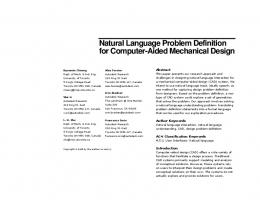
2. Requirements Definition To illustrate EA and the modeling language’s requirements, we present a case study of an EA project. Our case describes a bookstore company whose management decides to sell books via Internet. The management sets up an EA team who is in charge of the project. In this project, an enterprise model is developed. The bookstore’s enterprise model is made of levels. Figure 1 shows an informal representation of what is in the enterprise model. Market level
BookCoMarket
Business system level
Company level
Department level
Technology level
BookCoBis
ShipCo
PurchasingDep
OpApp
CustomerBis
BookCo
PubCo
WarehouseDep
Clerk
Additional level
Figure 1. Hierarchical representation of the systems represented in the enterprise model The market level represents BookCoMarket composed of the business systems BookCoBis and CustomerBis. The business system level represents companies or individuals working together to achieve a
0-7695-2268-8/05/$20.00 (C) 2005 IEEE
1
Proceedings of the 38th Hawaii International Conference on System Sciences - 2005
commercial goal. In our example, the business system of the on-line book company (BookCoBis) is composed of the book publisher (PubCo), of the company itself (BookCo), of the shipping company (ShipCo) and of the bank. The business system of the customer is composed of the end customer, the bank and the shipping company that delivers the books. The company level represents the departments operating inside the companies. More specifically, in this example, BookCo has a purchasing department (PurchasingDep) that collaborates with the warehouse department (WarehouseDep) for processing the customers’ orders. The department level represents employees and IT systems. In our example, the purchasing department consists of a clerk and of an order processing application (OpApp). One of the main goals of the project is to redesign OpApp to add e-commerce capabilities; but the project also needs to redefine the responsibilities of the employees and of the departments. Note that it would be possible to have additional levels for describing the IT system implementation (e.g. server level, component level and programming language class level). In such a project, the EA team has at least four challenges. First, the team must identify the different 1 systems (or objects ) and decide in which hierarchical level they exist (e.g. the market, the business, the company, the department level…). Second, the team has to model the actions happening between the systems belonging to the same level, as well as the corresponding responsibilities and properties of the systems. For example, it needs to represent what is happening between BookCo, ShipCo and PubCo when they serve the members of the customer business system. BookCo has the responsibility to find the books based on the description written in the customers’ orders. ShipCo is responsible for delivering books (possibly already packed by BookCo) and PubCo is responsible for providing ordered books that are unavailable in BookCo’s warehouse. In a similar way, the modeler should represent, in the other levels, what is happening between the systems and the systems’ responsibilities. Third, the EA team has to design and implement more than one system in parallel. For instance, in the department level, both the WarehouseDep and the PurchasingDep need to have new business processes. In the technology level, the application OpApp needs new functionalities and the clerks new job descriptions. Fourth, as there are multiple levels in the model, the team needs to maintain the traceability between levels: for example from BookCo downto PurchasinDep and WarehouseDep or from PurchasingDep to OppApp.
1
We model systems. Because we use the object-oriented paradigm to represent these systems, we can consider these systems as objects.
From these challenges, we identify the following four requirements: i) Multiple consistent levels: The language should provide the modeler with as many levels as she wants. The language should be consistent across the different levels. For convenience, it might use different pictograms in each level, but the modeling principles should be the same. ii) Adequate representation of actions: In every level, we should be able to represent what is happening between systems and the responsibilities of each system. These concepts are similar to Catalysis joint actions and localized actions [3]. iii) Multiple systems of interest: The model should allow the detailed representation of multiple systems. Thanks to this, it is possible to design more than one system at a time. iv) Existence of traceability relationships: The model should allow the representation of the relations between two representations, at different levels, of a same system and the relations between a system and its environment (made of systems). We call these relations traceability relationship. In SEAM, we have developed a modeling language, inspired from UML, which provides the necessary means for modelers to represent in a systematic way hierarchical systems. The language supports the hierarchical representation of objects, actions and states. In the next section, we present a precise definition of our language.
3. The SEAM modeling language In this section, we first present the foundations on which our modeling language is built (Section 3.1). We then present the language (Section 3.2). Note that the principles presented in this section are general. Our method, SEAM, illustrates the application of these principles.
3.1 Foundations for hierarchical modeling The foundations of our modeling language come from Miller’s level [7] (Section 3.1.1) and from our interpretation of the Reference Model of Open Distributed Processing (RM-ODP) [8] (Section 3.1.2). 3.1.1 Miller’s level. James Greer Miller introduced the concept of level in [7]. He made a thorough crossdiscipline analysis and synthesis of the functions and behavior of living systems. He published his results in 1995 [7]. His theory is called “General Theory of Living Systems” or “Living Systems Theory” (LST). To develop his theory Miller analyzed 4000 publications from
0-7695-2268-8/05/$20.00 (C) 2005 IEEE
2
Proceedings of the 38th Hawaii International Conference on System Sciences - 2005
multiple living systems disciplines. He then developed a model that can be used to reason about any living systems (from individual cells to supranational organizations such as the United Nations Organization). The main goal of LST is to unify all scientific disciplines that study and model livings systems. In particular, LST integrates structural and behavioral sciences but still keeps some of the specificities of the individual disciplines. On one hand, LST applies the same general theory (i.e., it uses the same concepts and principles) recursively at all levels of living systems. On the other hand, in each level, LST factors in level-specific theories coming, for example, for biology, medicine or social sciences. The result is an original combination of genericity and specificity. One of the most important concepts is that of level. According to Miller “…the universe contains a hierarchy of systems, each more advanced or ‘higher’ level made of systems of the lower levels”. He identifies seven distinct levels for living systems: cells (free-living cells and aggregated cells), organs, organisms (such as humans…), group (such as families, workgroups…), organization (such as commercial companies…), society (such as countries) and supra-national systems (such as intergovernmental organizations …). This level distinction is tightly linked to people’s experience in perceiving and studying the world of livings systems. Depending on the goal of the modeler, it is possible to have more or less levels. To be able to fully model enterprises, the model should not be limited to the IT and software-intensive systems but should also represent the business-related systems. For this, we borrow the concept of level from Miller. We call these levels the organizational levels. These levels establish the organizational level hierarchy. In the example of the on-line book company discussed earlier, the enterprise model has six organizational levels: market, business system, company, department, IT application and technology level. 3.1.2 RM-ODP. Within the levels, we use RM-ODP to represent what is perceived in the reality. RM-ODP is a standard that defines the concepts necessary to build “distributed information processing services to be realized in an environment of heterogeneous IT resources” [8]. RM-ODP also proves to be suitable for general modeling [9]. Our modeling language relies on the concepts defined in RM-ODP. According to RM-ODP part 2 (i.e. the foundations part of RM-ODP), an entity is any concrete or abstract thing of interest in the universe of discourse. An entity can be considered as atomic or as non-atomic (i.e. composed of components of the same kind). An entity is represented in the model as a model element. So, a model element can be seen as whole or as composite. A system may be referred to as an entity. A component of a system may itself be a system, in which case it may be called a
subsystem. The model element that corresponds to a system is an object. An object can be seen as whole (i.e. this corresponds to the external view of the object, also called model-based specification [10]) or as composite (i.e. this corresponds to the internal view, or implementation, of the object). Other kinds of entities can be modeled as action and state. Actions and states can also be seen as whole or as composite. An action or a state seen as composite can be broken down into component actions or states. These component actions or states can be further broken down into smaller component actions or states. This hierarchy of actions and states corresponds to the detail level hierarchy. The detail level hierarchy includes detail levels. It is orthogonal to the organizational level hierarchy defined in the previous section (in which an object is broken down into its component objects). In each organizational level, we can find multiple detail levels. One of our previously done research shows that all the terms we use above are the minimum set of concepts that need to be considered in general system modeling [11]. These concepts were formalized [12] using Alloy, a formal specification language [13]. According to RM-ODP part 3 (i.e. the architecture part of RM-ODP), a system specification has five viewpoints: enterprise, information, computational, engineering and technology viewpoint. In the context of hierarchical systems, we model organizational levels (cf. Miller) made of computational objects (i.e. an object that represents a system). The computational objects can be specified by either an information viewpoint (of the computational object seen as a whole) or by a computational viewpoint (of the computational object seen as a composite). In our modeling language we do not use the term information viewpoint but, instead, we use the term computational object as whole which is synonymous. Similarly, we do not use the term computational viewpoint but, instead, computational object as composite. A computational object as a whole is represented by information objects (IO) and localized actions (LA). The information objects are like attributes and represent the states of the computational objects. The localized actions represent the computational object’s responsibility. The information objects represents either the fact that a localized action executes (information objects called transactions) or parameters exchanged with the environment (information objects called parameters) or elements of “knowledge” (information objects called concepts). The “knowledge” of the computational object is about itself or about other computational objects belonging to the same organizational level. A computational object as composite is represented as component computational objects and actions happening between them that we call joint actions. Note that as RMODP part 2 just defines the term action, we have to define
0-7695-2268-8/05/$20.00 (C) 2005 IEEE
3
Proceedings of the 38th Hawaii International Conference on System Sciences - 2005
the localized actions and the joint actions. The names of these actions are taken from Catalysis [3].
“implementation” of la1 of Figure 2. Note that, in Figure 3, the modeler has hidden Comm and Co1.
3.2 Language definition Having taken our foundations from Miller [7], RMODP [8], we now proceed in defining our language. In Section 3.2.1 and 3.2.2, we illustrate the relevant model elements with examples using our CAD tool. We then define the model elements through a meta-model and through a formal description of the meta-model (which gives the semantics of the meta-model). In Section 3.2.1, we define the model element computational object. In Section 3.2.2, we define the model elements: joint action, localized action and information object. All these elements are defined as whole and as composite. In Section 3.2.3, all the elements of the language are put together to make a meta-model that is general enough to deal with an unlimited number of organizational and detail levels. The meta-model is in UML. The semantics is formalized using Alloy 2.0, which is a lightweight specification language based on set theory developed by Daniel Jackson at MIT [13]. While presenting the language, we highlight how our language fulfills the requirements identified in Section 2. 3.2.1 Organizational level in terms of computational objects as whole / composite. Figure 2 and 3 are screenshots that present two views of the same model. In Figure 2, the computational object Comm is broken down into two computational objects Co1 and Co2 participating to a joint action ja1. Co2 is viewed as whole and the localized action la1 stands for the responsibility of Co2 in its participation to ja1.
Figure 2. Comm as composite and Co2 as whole In Figure 3, the computational object Co2 is seen as composite, it has two component objects Co21, Co22. Co21 and Co22 collaborate through ja2 that is the
Figure 3. Co2 as composite, Comm & Co1 hidden. Once a computational object is seen as composite, it contains component computational objects and joint actions. By changing the view of the computational object from the whole (e.g. Co2 in Figure 2) to the composite (i.e. Co2 in Figure 3), the modeler moves to the next organizational level. The use of organizational levels in which computational objects exist both as whole and as composite allows the modeler to manage the hierarchical levels (from business down to code) in a systematic way. This computational object can represent any entities such as markets, companies, departments, people, IT systems, software components and programming classes. This illustrates how our language meets the requirement i) “multiple consistent levels” discussed in the previous section. By providing the capability for the modeler to represent multiple computational objects in the same organizational level, our language meets the requirement iii) “multiple systems of interest”. Let define the concepts of computational objects as whole and as composite. Table 1 gives the meta-model that defines these concepts and the semantics of the metamodel. As we can see in Table 1 a), the computational object as composite is broken down into computational objects (seen as whole) that are participants of one joint action2. The joint actions are described with preconditions and post-conditions that access information objects of the participating computational objects as whole. Note that breaking down a computational object results not only in component objects but also in a mediator. The mediator is a computational object that can only be treated as whole. It is responsible for dispatching joint actions. In the example of the bookstore, the mediator of the book company (BookCo) corresponds to 2
In the next section, we will present how multiple joint actions can be represented. They correspond to the detail level.
0-7695-2268-8/05/$20.00 (C) 2005 IEEE
4
Proceedings of the 38th Hawaii International Conference on System Sciences - 2005
the way the company exchanges goods and information between its departments (it is an abstract view of the lower organizational levels). A computational object seen as composite consists of component computational objects as whole and typically a joint action as whole in which the component objects participate. In our tool, computational objects are drawn using pictograms similar to UML subsystems.
Formalization
Meta-model
Semantics
Table 1 a): computational object as composite
3.2.2 Detail level in terms of joint actions, information objects and localized actions as whole / composite. Not only computational objects but also joint actions, localized actions and information objects can be treated as whole and as composite. Once the modeler breaks down a joint action, she moves down to the next detail level. Figure 4 is again a screenshot of our CAD tool. Co2 is shown at the next detail level compared to what is shown in Figure 2.
disj sig CCompuObject extends CompuObject { compu_whole : WCompuObject, compu_cpnts : set WCompuObject, compu_mediator : WCompuObject, ja : option WJointAction // 0 or 1 }{ one compu_mediator all c : compu_cpnts | c::compu_parent = this ja::compu_med = this }
Table 1 b) describes the computational object seen as whole. It has one information object as a whole to model the entire transaction of the computational object. This information object represents the whole state of the computational object. The Computational object also has one localized action that represents its entire behavior (i.e. the lifecycle of the object). This localized action changes the state of the information object and thus affects the state of the computational object.
Formalization
Meta-model
Semantics
Table 1 b): computational object as whole A computational object seen as whole contains an information object as whole and a localized action as whole. This object and action can be broken down further to reveal the detail “knowledge” and behavior of the computational object.
disj sig WCompuObject extends CompuObject { compu_parent : option CCompuObject, // 0 or 1 compu_composite : option CCompuObject, la : option WLocalizedAction, transaction : option WInfoObject, }{ this::compu_composite::compu_whole = this la::compu_owner = this transaction::compu_host = this }
Figure 4. Second detail level of Co2 and of the relevant part of its environment In Figure 4, the joint action ja1 (represented as a whole in Figure 2) is seen as composite; it is composed of ja11 and ja12. Correspondingly, the localized action la1 as composite consists of la11 and la12. The information object la1Txn as composite is composed of la1TxnSelf, la1Txn, la2Txn and Co1Concept (knowledge of Co2 about Co1). la1TxnSelf happens to be the “reference point” of the information object la1Txn after it is broken down into the component information objects la1Txn and la2Txn. The “reference point” (as it is unique for each information object) is useful for navigating in the component information objects. It has a role similar to the start and stop point in the behavior. In general, an information object may represent a transaction (standing for the execution of a localized action), a concept (which is the knowledge of a computational object about its environment or itself) or a parameter. As information objects are modified by localized actions, we also have different kind of localized actions: the interaction localized action that exchanges information with the environment through parameters (thus, observable from outside) and the internal localized action that has no exchange with the environment (unobservable from outside). By having joint actions in every computational object as composite, localized actions in every computational objects as whole and by allowing the representation of
0-7695-2268-8/05/$20.00 (C) 2005 IEEE
5
Proceedings of the 38th Hawaii International Conference on System Sciences - 2005
disj sig CJointAction extends JointAction { joint_whole : WJointAction, joint_self : WJointAction, joint_cpnts : set WJointAction, joint_ cnstrnts : set BehaviorConstraint }{ one joint_self this::joint_whole::joint_composite = this all c : joint_cpnts | c::joint_parent = this && c::compu_med = this::joint_whole::compu_med } disj sig WJointAction extends JointAction { joint_parent : option CJointAction, // 0 or 1 compu_med : CCompuObject, joint_composite : option CJointAction, participants : set WCompuObject }{ one compu_med all p:participants | p::compu_parent = compu_med }
A localized action represents a responsibility of a computational object as whole when it participates in a joint action. The localized action can be treated either as whole or as composite. In our tool, it is drawn using the same pictogram as an UML action state.
Meta-model
Semantics
Table 2 c): Localized action as composite / whole
disj sig CInfoObject extends InfoObject { info_whole : WInfoObject, info_self : WInfoObject, info_cpnts : set WInfoObject, concepts : set WInfoObject, parameters : set WInfoObject, navs : WInfoObject -> WInfoObject }{ one info_self this::info_whole::info_composite = this all c : info_cpnts + concepts + parameters | some n : navs | c::info_parent = this && c::compu_host = this::info_whole::compu_host && n.info_self = c } disj sig WInfoObject extends InfoObject { info_parent : option CInfoObject, // 0 or 1 compu_host : WCompuObject, info_composite : option CInfoObject }{ one compu_host }
Formalization
Formalization
Meta-model
Semantics
Table 2 a): Information object as composite / whole An information object represents a piece of information in a computational object as whole. It may represent a transaction, a concept or a parameter. It can be treated either as whole or as composite. Once treated as composite, it has an entry point from which navigation links are going to the components. In our tool, it is drawn using the same pictogram as an UML class.
A joint action represents an action happening between computational objects. These objects are called participating objects. The pre-condition and post-condition of a joint action can be described in terms of its participating objects seen as whole. In our tool, it is drawn using the same pictogram as an UML collaboration.
Meta-model
Semantics
Table 2 b): Joint action as composite / whole
Formalization
actions at different levels of detail, our language fulfills the requirement ii) “adequate representation of actions”. Note that our tool keeps the traceability between the concepts and what it represents in the system’s environment. This is done by a “trace” relationship such as the relation going from Co1Concept to Co1 in Figure 4. This, together with the possibility to represent computational objects as whole and as composite and with our representation of actions, enable our language to satisfy the requirement iv) “existence of traceability relationships”. In Table 2, we define the three model elements: information object, join action, and localized action. These elements can be seen as whole or as composite along the detail level hierarchy. When an element as whole becomes a composite element, this results in component elements together with constraints on how they are put together. The constraints for the joint actions and localized actions seen as composite are behavioral constraints. They may determine the sequence of the component actions. The constraint for a composite information object represents the navigation between the component information objects.
disj sig CLocalizedAction extends LocalizedAction { localized_whole : WLocalizedAction, localized_self : WLocalizedAction, interactions : set WLocalizedAction, internals : set WLocalizedAction, localized_cnstrnts : set BehaviorConstraint }{ one localized_self this::localized_whole::localized_composite = this all c : interactions + internals | c::localized_parent = this } disj sig WLocalizedAction extends LocalizedAction { localized_parent : option CLocalizedAction, compu_owner : WCompuObject, localized_composite : option CLocalizedAction, affecteds : set WInfoObject }{ one compu_owner all a : affecteds | a::compu_host = compu_owner }
0-7695-2268-8/05/$20.00 (C) 2005 IEEE
6
Proceedings of the 38th Hawaii International Conference on System Sciences - 2005
3.2.3 Combining organizational and detail levels. We eventually come to one complete meta-model where each element can be toggled between the whole and the composite view (see Figure 5). The detail level can be inferred via the composition relationship connecting Joint Action, Information Object and Localized Action as composite to the respective generalized element. The constraints of the two roles of this composition ({detail n+1} and {detail n}) say that the element as composite is one detail level above the generalized element. Similarly, the organizational level can be inferred via the composition connecting Computational Object as composite to the generalized Computational Object, which is one organizational level below the composite one ({org n+1} and {org n}). In fact, the complete metamodel is simply made by assembling the meta-models shown in Table 1 and Table 2. In a similar way, the Alloy code presented in each table can be put together to make a complete specification of the meta-model. As discussed previously, our language supports traceability. Thanks to traceability, our CAD tool can help the modeler navigate those diagrams although they are separately displayed. This tool should manage all model elements in a way that diagrams are just extracted view
based on some criteria (e.g. a diagram can represent one given computational object (as whole or as composite), with or without its environment, and doing a specific localized action (as whole or as composite). We have tested this language with a CAD tool that we developed. The tool is a client-server web-based application. The client is available for downloading [14]. The data structure in the implementation of the tool looks very similar to Alloy code listed in Table 1 and Table 2. Our modeling language and CAD tool have been used in various projects. We have used it in some student work in industry for small business process reengineering projects. We are currently using it in a construction project for a new building for our school. We are making an enterprise model of the school that describes the business goals we have for the construction project. From this, we derive the infrastructure to deploy and the requirements of our new IT system. We also have a project in which we are defining the operational semantics for the language [15]. Thanks to this we will be able to do model checking (e.g. to compare two representation of a same system, represented in two different organizational levels).
Figure 5. Complete meta-model
0-7695-2268-8/05/$20.00 (C) 2005 IEEE
7
Proceedings of the 38th Hawaii International Conference on System Sciences - 2005
searching) that uses a Java class OrderPrinterClass (for printing orders) and a JDBC connector (see Figure 7).
4. Case study In this section, we illustrate how to use our language to model the bookstore case study presented in Section 2. We have one enterprise model, represented by a serie of diagrams. They represent all levels, from the market level down to the internals of the IT system. The EA team uses these diagrams to analyze and design the multiple systems found in the business and IT levels. These diagrams were created with our CAD tool [14] and were redrawn to save space. In these diagrams, the levels to which the objects and actions belong are visually illustrated with a tagged value {org x, detail y}. As we can see in Figure 6, at the top organizational level, BookCoMarket as composite consists of two business systems: BookCoBis and CustomerBis. BookCoBis sells books to CustomerBis. They collaborate through the joint action sale. BookCoBis is responsible for performing the localized action Mfg_Sale. In the second organizational level, BookCoBis as composite is composed of the company BookCo that collaborates with PubCo and ShipCo to fulfill the joint action mfg_Sale that is in fact the implementation of the localized action Mfg_Sale. In the third organizational level, BookCo as composite contains two departments: PurchasingDep (for selecting books and processing orders) and WarehouseDep (for packing selected book). Note that both of them are specified as whole when participating in the joint action market. The joint action market as composite has component actions select, pack and order that all belong to the second detail level (whereas market as whole belongs to the first detail level). PurchasingDep as whole is also specified in the second detail level with MarketTxnSelf, SelectTxn, OrderTxn (information objects representing the transactions) and with localized actions Select, Order. Note the difference of responsibilities between WarehouseDep and PurchasingDep. WarehouseDep does the localized action Pack and the PurchasingDep the localized action Select. In addition the Order localized action is different in WarehouseDep and in PurchasingDep. In the fourth organizational level (Figure 7), PurchasingDep as composite shows that a Clerk operates the IT system OpApp. What is happening between the Clerk and OpApp is modeled as the joint action operate. OpApp’s responsibilities is represented as the localized action Work. What Work means would be visible if we would get to the next detail level of OpApp as whole (not shown in figures). In the fifth organizational level (technology level) where OpApp as composite is represented, it is possible to see a SearchApplet (a Java applet that is accessed by the clerk), a SearchServlet (a Java servlet responsible for
BookCoMarket {org 1}
sale {org 2, detail1}
CustomerBis {org 2}
BookCoBis {org 2} Book {org 2}
MfgSaleTxn {org 2, detail 1} Mfg Sale {org 2, detail 1}
BookCoBis {org 2}
PubCo {org 3}
mfg_sale {org 3, detail 1} BookCo {org 3}
ShipCo {org 3}
MarketTxn {org 3, detail 1} Market {org 3, detail 1}
BookCo {org 3}
WarehouseDep {org 4}
MarketTxn {org 4, detail 1} MarketTxnSelf {org 4, detail 2}
PackTxn {org 4, detail 2}
OrderTxn {org 4, detail 2}
Market {org 4, detail 1} Pack {org 4, detail 2}
Order {org 4, detail 2}
market {org 4, detail 1} pack {org 4, detail 2} select {org 4, detail 2} order {org 4, detail 2}
PurchasingDep {org 4} MarketTxn {org 4, detail 1} MarketTxnSelf {org 4, detail 2}
SelectTxn {org 4, detail 2}
OrderTxn {org 4, detail 2}
Market {org 4, detail 1} Select {org 4, detail 2}
Order {org 4, detail 2}
Figure 6. Model of the online bookstore for business-related organizational levels The model we built has 6 organizational levels. (four in Figure 6 and two in Figure 7). We could consider
0-7695-2268-8/05/$20.00 (C) 2005 IEEE
8
Proceedings of the 38th Hawaii International Conference on System Sciences - 2005
adding levels to describe how the applet and the servlet are built. PurchasingDep {org 4}
operate {org 5, detail 1}
Clerk {org 5}
OPApp {org 5}
WorkTxn {org 5, detail 1} Work {org 5, detail 1}
OpApp {org 5}
SearchApplet {org 6}
SearchServlet {org 6} ServiceTxn {org 6, detail 1}
run {org 6, detail 1}
JDBC {org 6}
OrderPrinterClass {org 6}
Service {org 6, detail 1}
Figure 7. Model of the online bookstore for ITrelated organizational levels We can see that joint actions are expressed in every composite computational object. For each joint action, the participant computational objects have a localized action expressing their responsibility. These localized actions correspond to a joint action in the next organizational level. This illustrates the how our language satisfies the requirements i) “multiple consistent levels”, ii) “adequate representation of actions”, and iv) “existence of traceability relationships”. By permitting to work on multiple systems in parallel, our language satisfies the requirement iii) “multiple systems”: With our CAD tool, the modeler can navigate up and down the hierarchy by selecting the relevant model element (typically a computational object, a joint action or a localized action) and by using a pop-up menu to toggle between whole and composite. Within an organizational level, the modeler can also hide or show the environment of the computational object of interest.
5. Related work In this section, we position our contribution with respect to the existing object-oriented languages and methods such as UML, Catalysis, Kobra, SysEng and OPM. In this paper, we do not consider the Zachman framework [16], popular in EA, as it is not objectoriented. Our choice of an object-oriented approach is justified by our attempt to have a consistent modeling paradigm between IT and business levels. In software engineering, objects are widely used and UML has made a significant impact.
UML [2], defined and managed by Object Management Group (OMG) [17], is the industry-standard modeling language developed originally for software development. In the profile created for business modeling, the object systems, organizational units and work units are all subsystems. They differ only in stereotypes. Since a subsystem in UML meta-model can contain UML classifiers, which may be again subsystems, the business hierarchy can be established by having an organizational unit being composed of other units. Our modeling language also uses the subsystem notation for computational objects but it provides joint actions and localized actions in every organizational level (which is not the case in UML). Therefore, the hierarchy has not only structures but also behaviors represented in a consistent way. Catalysis [3], defined by Desmond D’Souza and Alan C. Wills, is a development process that addresses business and software. Catalysis analyzes and designs at three levels: business, IT system and software components. Catalysis uses its own modeling notation, inspired by UML. A conceptual model [18] defines the notation. We base our work on the Catalysis approach (and, in particular, on the joint actions and localized actions). Our initial goal was to develop a CAD tool for Catalysis. As a result, we have defined a meta-model more precise than the one provided by the Catalysis authors [18] and which provides a more general approach to the concept of organizational and detail levels. System Engineering (SysEng) [4] also defined by the OMG [17] is a development process that addresses the design of systems in general (e.g. airplanes) using the UML notation. The Conceptual Model [19] of SysEng addresses the hierarchical modeling via the loop on the system/subsystem as well as on the component. Both of them have the loop aggregation “Made up with”. Our final meta-model also have a loop on Computational Object that establishes the hierarchy along organizational levels. Our difference lies in the fact that we do not have sub-systems and components in our meta-model but only computational objects. Thanks to this, our language becomes more consistent and traceable across the organizational levels. As SysEng is based on UML, the comments made about UML also apply to SysEng. KobrA [5], developed by Colin Atkinson et al., addresses component-based software development. It proposes a recursive model that describes the IT system, its components and the Java classes using the UML notation. In KobrA meta-model [20], a component can be either a UML subsystem or a flat class. KobrA defines a recursive top-down approach that allows the modeler to interleave the specification and the realization of the components starting from a top-level context [5]. In our language, both the specification (i.e. information object and localized action) and “realization” (i.e. computational object and joint action) appear in all organizational levels.
0-7695-2268-8/05/$20.00 (C) 2005 IEEE
9
Proceedings of the 38th Hawaii International Conference on System Sciences - 2005
Our language thus can deal with not only software-related but also business-related organizational levels. As Kobra is based on UML, the comments made about UML also apply to Kobra. OPM [6], defined by Dove Dori, addresses the modeling of systems in general and can be used from business processes modeling down to software implementation modeling. OPM defines three main model elements: object, process and state, together with some mechanisms that help the modeler define a hierarchy of systems. The notation is specific to OPM. With a CAD tool called OpCat that was particularly developed for OPM [21], the modeler can manage the complexity of a hierarchical system that is mainly related to the levels via two mechanisms: in-zooming / out-zooming and unfolding / folding [21]. Our language has strong similarities to OPM but is much closer to UML. In addition, the meta-model of our language makes the hierarchy of organizational levels and detail levels more explicit than the OPM meta-model.
6. Conclusion Modeling object-oriented hierarchical systems requires: (1) a consistent way to model hierarchical levels (from business down to IT); (2) the possibility to model what happens between systems (joint actions) and systems’ responsibilities (localized actions) and this in all necessary organizational and detail levels; (3) to work on multiple systems of interest, and (4) to have traceability relationships. To meet these requirements, we propose a new modeling language that is based on Miller’s Theory of Living Systems [7] and on RM-ODP [8]. The main contribution of this work is the definition of four basic modeling concepts (computational object, joint action, information object and localized action) together with the application of two complementary views (composite/whole). These two views allow us to define the concepts of organizational level hierarchy and detail level hierarchy. These concepts are general and can be taken by the other hierarchical modeling approach. A CAD tool is implemented to show how our modeling language practically works. Through various examples, we have validated the language and tool. Our experience with the tool shows that the user interface shall be designed with great care. As the models are complex, the tool should reduce this complexity for the user. This is the direction of our future work.
7. References [1] A. Wegmann, "On the Systemic Enterprise Architecture Methodology (SEAM)," presented at ICEIS 2003, Angers, France, April 2003. [2] OMG, UML 1.5 Specification, http://www.omg.org/technology/documents/formal/uml.htm [3] D. Francis D'souza, Cameron Wills, A., Object, Components and Frameworks with UML, The Catalysis Approach: AddisonWesley, 1999. [4] OMG, System Engineering, http://syseng.omg.org [5] C. Atkinson, Paech, B., Reinhold, J., Sander, T., "Developing and applying component-based model-driven architectures in KobrA," presented at EDOC 2001, Seattle, USA, September 2001. [6] D. Dori, Object-Process Methodology, A Holistic Systems Paradigm: Springer Verlag, 2002. [7] J. G. Miller, Living Systems: University of Colorado Press, 1995. [8] OMG, "ISO/IEC 10746-1, 2, 3, 4 | ITU-T Recommendation, X.901, X.902, X.903, X.904, Reference Model of Open Distributed Processing," 1995-1996. [9] A. Wegmann, Naumenko, A., "Conceptual Modeling of Complex Systems using an RM-ODP based Ontology," presented at EDOC 2001, Seattle, USA, September 2001. [10] B. Schätz, Pretschner, A., Huber, F., Philipps, J., "Modelbased development of embedded systems," in In Advances in Object-Oriented Information Systems, Lecture Notes in Computer Science 2426, 2002. [11] A. Naumenko, "Triune Continuum Paradigm: a paradigm for General System Modeling and its applications for UML and RM-ODP," in School of Computer and Communication Sciences. Lausanne: Swiss Federal Institute of Technology, Lausanne, 2002. [12] A. Naumenko, Wegmann, A., Genilloud, G., Frank, W.F., "Proposal for a formal foundation of RM-ODP concepts," presented at ICEIS/WOODPECKER 2001, Setúbal, Portugal, July 2001. [13] MIT, The Alloy Constraint Analyzer, http://alloy.mit.edu/ [14] L. S. Lê, CAD tool for Systemic Enterprise Architecture Modeling, http://lamspeople.epfl.ch/le/SEAMtool [15] I. Rychkova, Wegmann, A., Balabko, P., "Operational ASM semantics behind Graphical SEAM notation," presented at FMOODS/DAIS 2003 Student Workshop, Paris, France, November 2003. [16] J. A. Zachman, "A Framework for Information System Architecture," IBM System Journal, 1988. [17] Object Management Group, http://www.omg.org/ [18] Catalysis Concept Map, http://www.catalysis.org/overview/concepts/conceptmap/graphical-concept-map.htm [19] System Engineering Conceptual Model (Work in Process), http://syseng.omg.org [20] Meta-model for KobrA method, www.iese.fhg.de/Publications/book/Guides/Metamodel.pdf [21] D. Dori, Reinhartz-Beger, I., Sturm, A., "OPCAT - A Bimodal CASE Tool for Object-Process Based System Development," presented at ICEIS 2003, Angers, France
0-7695-2268-8/05/$20.00 (C) 2005 IEEE
10