[10]â[12] and in sigmaâdelta modulation [13]. Notch filters, where the rejected signal component has normalized frequency near zero, have pole(s) close to the ...
IEEE TRANSACTIONS ON CIRCUITS AND SYSTEMS—II: ANALOG AND DIGITAL SIGNAL PROCESSING, VOL. 45, NO. 1, JANUARY 1998
41
Delta Operator Realizations of Direct-Form IIR Filters Juha Kauraniemi, Timo I. Laakso, Senior Member, IEEE, Iiro Hartimo, Senior Member, IEEE, and Seppo J. Ovaska, Senior Member, IEEE
Abstract— The use of the delta operator in the realizations of digital filters has recently gained interest due to its good finite-word-length performance under fast sampling. We studied efficient direct form structures, and show that only some of them can be used in delta configurations, while others are evidently unstable. In this paper, we focus on the roundoff noise analysis. Of all the direct-form structures, the direct form II transposed (DFIIt) delta structure has the lowest quantization noise level at its output. This structure outperforms both the conventional direct-form (delay) structures, as well as the state-space structures for narrow-band low-pass filters with respect to output roundoff noise. Excellent roundoff noise performance is achieved at the cost of only a minor additional implementation complexity when compared with the corresponding delay realization. Complexity of a signal processor implementation of the DFIIt delta structure, which was found to be the most suitable delta structure for signal processors, is compared with those of the direct form and state-space delay structures. In addition, some hardware implementation aspects are discussed, including the minimization of the internal word length. Index Terms—Delta operator, direct-form structures, roundoff noise.
I. INTRODUCTION
R
EDUCTION of finite-word-length effects in digital filters has been studied in a large number of papers during the past few decades. State-space structures which minimize the output roundoff noise were studied in [1]–[3], and coefficient sensitivity minimizing networks were analyzed in [4] and [5]. An efficient method to reduce the effects due to signal quantizations is the concept of error feedback, sometimes called residue feedback, error spectrum shaping, or noise shaping [6]–[8]. A comprehensive tutorial of a number of low-noise and low-sensitivity digital filter structures, including wave digital filters, is given by Vaidyanathan in [9]. When sampling rates much higher than the bandwidth of interest are used, finite-word-length effects get worse. For example, the poles of a narrow-band low-pass filter cluster near the point in the plane, and make the filter very noisy Manuscript received September 20, 1995; revised October 17, 1996. This work is a project of the Institute of Radio Communications (IRC) and is supported by the Technology Development Center (TEKES). This paper was recommended by Associate Editor W.-C. Siu. J. Kauraniemi and I. Hartimo are with the Laboratory of Signal Processing and Computer Technology, Helsinki University of Technology, FIN-02150 Espoo, Finland. T. I. Laakso is with the Laboratory of Telecommunications Technology, Helsinki University of Technology, FIN-02150 Espoo, Finland. S. J. Ovaska is with the Laboratory of Electric Drives and Power Electronics, Helsinki University of Technology, FIN-02150 Espoo, Finland. Publisher Item Identifier S 1057-7130(98)00064-0.
and sensitive to coefficient quantization. Fast sampling relative to signal bandwidth is commonly used in digital control [10]–[12] and in sigma–delta modulation [13]. Notch filters, where the rejected signal component has normalized frequency in the near zero, have pole(s) close to the point plane. Recently, delta operator realizations have gained interest due to their good finite-word-length performance under fast sampling [10]–[12], [14]–[19]. Similar structures, even called delay replaced structures, are studied in [20]–[22]. However, these studies on delta structures concentrate mainly on the state-space structures, and no detailed comparison between different delta structures has, to our knowledge, been reported yet. One of the simplest and probably the most popular structures are the direct-form (DF) structures, which have received little interest in delta configurations [18], [19]. In this paper, implementation of recursive digital filters using DF delta structures is studied. We analyze and compare different second-order DF sections (DFI and DFII, including their transposed forms). The focus is on the roundoff noise analysis. Moreover, we study the minimization of roundoff noise in parameter of the DFII structures via optimization of the The optimal value is the delta operator derived within the scaling constraints to prevent overflow. Implementation aspects are discussed, indicating that rounding the optimal parameter to the closest power of two results in efficient VLSI implementations. Complexities of some signal processor implementations are compared. The cost of the delta operator realizations is the increased implementation complexity. This is typical likewise in other low-noise structures. Besides additional arithmetic operations, the complexity is increased in the fixed-point implementation by the need for the enhanced precision inverse delta operations [15]–[19]. It is not possible in a signal processor implementation to obtain savings in the code length by using less than exact double precision. However, in an ASIC implementation, additional bits increase the die area and, therefore, it is desirable to limit their number to as few as possible [23]. It is shown that the optimal parameter can result in considerably when the lower output roundoff noise than choice internal word length is minimized. In addition, it is shown that when the poles of the system certain delta structures have superior are close to roundoff noise properties over the traditional delay structures. Improvement in the roundoff noise performance is achieved at the price of a more complex implementation. However, by using simple structures, such as direct-form structures, an
1057–7130/98$10.00 1998 IEEE
42
IEEE TRANSACTIONS ON CIRCUITS AND SYSTEMS—II: ANALOG AND DIGITAL SIGNAL PROCESSING, VOL. 45, NO. 1, JANUARY 1998
increase in the computational complexity is moderate. As a consequence, savings in the hardware may be obtained using the delta realizations instead of increasing the word length of the delay realized filter. Our paper is organized as follows. In Section II, the delta operator is defined, and the conversion of -domain transfer functions into the delta domain is studied. In Section III, the standard roundoff noise model is reviewed. The analysis of the cascaded second-order direct-form sections is carried out in Section IV. Section V is devoted to the comparison of different delta and delay structures. Two sixth-order low-pass filters were designed as examples, and the performance of various structures is compared in Section VI. Finally, conclusions are drawn in Section VII. The derivation of the roundoff noise minimizing value of the parameter is presented in the Appendix. II. CASCADED DELTA DOMAIN TRANSFER FUNCTIONS To achieve good finite-word-length performance under fast sampling, the delta operator will replace the forward shift operator in the digital filter [10]. The delta operator (forward difference) is defined as (1) is the forward shift operator and is proposed where to be the sampling interval [10]. In our treatment, the parameter is not tied to a true sampling interval of the system, but it is viewed as a free parameter that can be chosen, e.g., to minimize roundoff noise. This will be studied in detail in Section IV. One very important justification for the choice of forward difference (1), as the delta operator, is that recursive delta parameterized systems are directly implementable, i.e., there are no delay-free loops in them. In the case of backward difference or bilinear operator , a corresponding recursive system cannot be implemented simply by replacing delays by the inverse of the corresponding operator and changing the system parameters, due to the delay-free loops that both operators produce into the recursive systems. When a causal delta operator filter is implemented, a realization of the inverse delta operator is needed. From (1), we get (2) has an unstable pole at In filter Notice that realizations, these unstable poles have to be canceled by zeros at in order to obtain a stable realization of a stable transfer function. In practice, a cascade of second-order sections is preferred over a direct high-order implementation due to its advantageous finite-word-length properties. The -domain transfer function of a cascaded IIR filter is (3)
TABLE I RELATIONSHIP BETWEEN THE COEFFICIENTS OF THE SECOND-ORDER DELTA AND z POLYNOMIALS
where
is the gain of the overall transfer function and (4)
is the transfer function of the th section. The delta realization of (3) is obtained by converting each section (4) into the delta domain. The corresponding delta form transfer function is (5) The coefficients of the delta domain transfer function are given in Table I. Note that the parameter can be chosen independently for each section, and is thus written with the Different direct form corresponding section subindex structures to implement (5) are studied in detail in Section IV. III. ROUNDOFF NOISE MODEL Quantization is a nonlinear operation, and in large systems, it is difficult to model deterministically. The key simplification is to model the quantization error statistically as an additive noise sequence [24], [25]. The error sequence is modeled as a white noise process uncorrelated with the input signal It is also assumed that roundoff noise introduced at one node is uncorrelated with that introduced at any other node in the system. Therefore, superposition holds for the noise components. The validity of this stochastic noise model is discussed, e.g., in [26]. If quantization is done by rounding, the process has a zero mean and the variance is [24] (6) where is the total word length, including the sign bit. It was mentioned earlier that in delta realizations using fixedpoint arithmetic, enhanced precision inverse delta operations are required. If a single precision word has a bit representation, double precision here means a bit word, where is the coefficient word length. Moreover, enhanced precision means a word length of bits and Noise variances due to the quantizations to these word lengths are denoted as (single precision), (double precision), and (enhanced precision). The output noise variance (the average power of the quantization error) due to any particular noise source is (7)
KAURANIEMI et al.: DELTA OPERATOR REALIZATIONS OF IIR FILTERS
43
(a)
(b)
(c)
(d)
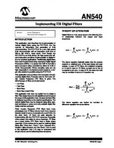
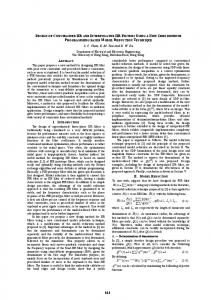
Fig. 1. Flow graph presentations of direct form delay structures: (a) DFI, (b) DFIt, (c) DFII, and (d) DFIIt.
where is the transfer function from the th noise source in the th section to the output in the scaled network and the subscript is either , or The noise transfer functions of the scaled system are related to those of the unscaled network as (8) is the scaling transfer function of the th section where (in the unscaled network) and is the norm of the function [27]. The usual roundoff noise performance measure is the noise gain, which tells how much the output roundoff noise is amplified over the unit noise variance (6). It is defined as (9) Noise gain in decibels is defined as IV. CASCADED DIRECT FORM SECTIONS Direct-form (DF) structures [28] are widely used in digital filtering due to their simplicity. Signal flow graphs of DF structures are presented in Fig. 1. Analysis of the delay realizations can be found in several books on digital signal processing, for example, [27], [28]. A major drawback of the DF delay structures is the poor finite-word-length performance, especially when the poles of the system are clustered near the point in the plane. In this case, the delta operator can substantially increase the performance of certain DF structures. Direct-form delta realizations are obtained from delay structures by replacing delays with inverse delta operators, given in (2), and changing coefficients to those of the corresponding delta domain transfer function (5).
A. Direct-Form I (DFI) Structures In the DFI structure, the zeros are implemented before the poles. As the poles introduced by the inverse delta operators are not canceled beforehand, this part of the filter is unstable, causing the summations in the blocks to overflow. As a consequence, the DFI structure is not suitable for the delta operator realization. In the direct-form I transposed (DFIt) structure, the poles are implemented before zeros, and the unstable poles introduced by the inverse delta operators are canceled before any summations. The delta operator realizations using fixedpoint arithmetic in general require enhanced precision internal operations. This is the case as well when the delta DFIt structure is implemented, which can be reasoned as follows: it is seen from Fig. 1 (if converted into delta structure) that if the inverse delta operation is performed in single (or enhanced) precision, i.e., signal is quantized after each multiplication, the noise sources before the blocks have unstable transfer functions. In order to function properly, the delta-realized DFIt filter necessitates double precision internal arithmetic. The DFIt structure needs twice as many blocks as the DFII structures. It follows that either additional hardware or more double precision memory reads and writes in software implementation are required. This increases the implementation complexity, and hence the DFII structures are more attractive for the delta operator realization. B. Direct-Form II (DFII) Structure 1) Scaling Transfer Functions: When the gain of the transfer function is embedded to the coefficients of the nonrecursive part of the filter, the summation at the output is scaled and not likely to overflow, and there are totally three summations which have to be protected against overflow. In Fig. 2(a), the signals after these summations are denoted as ,
44
IEEE TRANSACTIONS ON CIRCUITS AND SYSTEMS—II: ANALOG AND DIGITAL SIGNAL PROCESSING, VOL. 45, NO. 1, JANUARY 1998
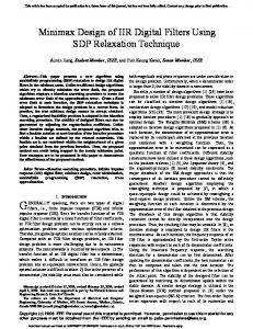
Fig. 3. Finite-word-length implementation of the � 01 operator.
2) Noise Transfer Functions: The noise transfer functions from the error sources in the th section of the unscaled network are (15)
(a)
(16)
(b) Fig. 2. Second-order delta operator realized (a) DFII and (b) DFIIt section. Quantizations to short double precision are drawn with dashed line. If exact double precision is used, these quantizations do not exist.
(17) cause additional noise sources; see Multiplications by Fig. 3. The transfer functions from these sources are
and . Solving for the transfer functions from the input to each of these signals results in the th section (10) (18) (11)
(12) It is evident that when the poles of the system are inside the unit circle, all of the scaling transfer functions are stable, and no stability problems due to the inverse delta operations are encountered. If the unscaled numerator coefficients of the th section are the corresponding scaled coefficients are
(19) where is the section index. As the noise sources are due to the quantization to the enhanced or double precision, increase of the output noise level due to these sources depends on the word length used in the line. If enhanced precision is used, a further quantization and a corresponding noise source exist after each coefficient. Effectively, these sources are in the input of each section, and the transfer functions are (20)
(13) where is the forward scaling coefficient and is the inverse of the largest norm of the scaling transfer functions in the th section
The total output roundoff noise variance in the case of double precision is
(14) (21)
KAURANIEMI et al.: DELTA OPERATOR REALIZATIONS OF IIR FILTERS
45
where is the variance of noise source due to the quantization to double precision and an asterisk means that scaling is embedded, see (8). If enhanced precision is used, the total variance is
(22) in the first section and when , see Fig. 2(a). 3) Enhanced Precision in Hardware Implementation: If some degradation to output-signal-to-roundoff-noise ratio is allowed, the number of additional bits in enhanced precision can be relaxed. If the noise variance (22) is allowed to be times larger than (21), the number of required extra bits can be expressed as shown in (23) at the bottom of the page, where is the number of bits in the coefficients and is the smallest integer larger than or equal to Equal is assumed to be used in every section. By the choice of the number of bits required to a maximum of 3 dB increase in the noise variance are obtained. 4) Optimization of the Delta Parameter: Both the noise variances (21) and (22) are functions of the parameter , and a roundoff noise minimizing value for it can be derived. Derivation of the optimal for the DFIIt structure is presented in the Appendix. For the DFII structure, it is similar, and is therefore omitted here; only the results are given. The optimum value of the parameter can be found using the procedure presented in the Appendix. In the examples we have looked at, the optimum turned out to be where
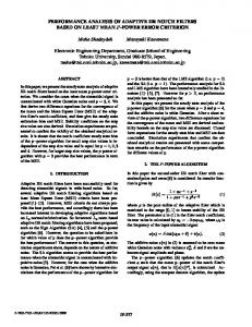
(24) where jecture that this filters using parameter is a second-order function are at
. Thus, we conwill be optimal for the narrow-band low-pass scaling. The rounded optimum value of the sketched as a function of the pole angle for section in Fig. 4. The zeros of the transfer in the plane.
Fig. 4. Rounded optimal values for structure.
1
in the second-order delta DFII
C. Transposed Direct-Form II (DFIIt) Structure 1) Scaling Transfer Functions: The delta DFIIt is shown in Fig. 2(b). In each section, there are three summations critical for scaling denoted by and , where is the number of second-order sections. Notice that in each inverse delta operation, an addition is performed, but when two’s complement arithmetic is used, these are allowed to overflow only if the correct total values of the summations and do not overflow. In a specific case , the summation alone has to be scaled, and the scaling transfer function for the mth section of the unscaled system is (25) It is important to perceive that when is not equal to unity, summations before the inverse delta operators are not allowed to overflow. Transfer functions to these points are
(26)
(27)
(23)
46
IEEE TRANSACTIONS ON CIRCUITS AND SYSTEMS—II: ANALOG AND DIGITAL SIGNAL PROCESSING, VOL. 45, NO. 1, JANUARY 1998
where is the section index. The coefficients in (27) are equal to those in (17) since the systems are transposes of each other. Notice that (26) and (16) do not represent the same transfer function, see Fig 2. From (8) and (25)–(27), it is obvious cannot be arbitrarily small. If it is very that the parameter small, strict scaling has to be used, and large back scaling is required to keep the overall gain equal to unity. Strict scaling will waste the dynamic range and increases the noise level at the output. The value for the parameter resulting in minimum output roundoff noise is presented later in this section. If the unscaled numerator coefficients of the th section are the corresponding scaled coefficients are
(28) where is the back scaling coefficient, is the inverse of the largest norm of the scaling transfer functions of the th section
(31) and (32) by dividing them by (33)
(34) The noise transfer functions of the scaled system are related to the those of the unscaled network as (35) where the subscript is either [(29)–(31)] or [(32) or (33)] is the number of the second-order section. If and is used for all and only one quantization is assumed in each section, the total output noise variance is (36) is smaller than unity If enhanced precision is used and the total output noise variance is for all
(29) and
Note that when the norm of (25) is the largest for and scaling is used, is equal to the gain of the transfer function; hence, no back scaling is required. 2) Noise Transfer Functions: When several second-order sections are cascaded, the noise transfer functions of the unscaled network are (30)
where . If double precision, i.e., multiplication, results are not quantized before the inverse delta operators, and is used in every section, only noise sources having transfer functions (30) exist. Equation (30) is independent and because multiplication by smaller than 1 of introduces more noise sources, minimum roundoff noise is for all If enhanced precision is obtained by using used, more noise sources will result, having transfer functions (31)
(32) These transfer functions are directly proportional to , and may no longer be optimal in the roundoff noise sense. The transfer functions from the noise sources due to smaller than unity are obtained from the multiplication by
(37) It is assumed that no back scaling is required. If this is not the case, quantization is also needed after the back scaling coefficient at the output of the system and one more noise source exists having a unity transfer function. It follows from (25)–(27) and (30)–(35) that the total noise variance (37) is a function of the parameter , and the minimum with respect to it can be derived. 3) Enhanced Precision in Hardware Implementation: In practical hardware implementations, the number of extra bits line should be as small as possible. If some deused in the terioration in the roundoff noise performance is allowed, when compared with the ideal case given by (36), an expression for the required extra bits can be derived from (36) and (37). If times increase in the output noise power is allowed, the is following formula for the number of the additional bits obtained as shown in (38) at the bottom of the page. It is assumed that equal word length is used in the line of every section. It was noticed in the previous section line is used, the that, when exact double precision in the noise gain of this structure is independent of the value of However, when signal values have to be quantized in the line, it may be advantageous to choose In signal
(38)
KAURANIEMI et al.: DELTA OPERATOR REALIZATIONS OF IIR FILTERS
47
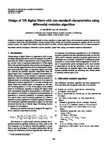
(a) Fig. 5. Rounded optimal values for structure.
1
in the second-order delta DFIIt
processor implementation, we cannot achieve any savings in the code length by using less than exact double precision, but in an ASIC implementation, limiting the number of extra bits to as few as possible is desirable to save die area [23]. 4) Optimization of the Delta Parameter: To determine the optimum value for the parameter , expression (37) has to be minimized with respect to The minimum is found either at the zero points of the derivative or at the endpoints of the interval of interest. Minimization is straightforward, but lengthy, and it is carried out in the Appendix. It was discovered that there are at most three different local minima, one of them being the global minimum, and thus the desired solution. However, according to our experience, when a narrow-band low-pass filter is designed and the -scaling strategy is used, the optimum will be
(b) Fig. 6. Noise gain of the second-order delta DFIIt section as a function of the pole angle and parameter : The pole radius (a) r : and (b) r : : The number of extended precision bits Bd :
1
=3
= 0 90
= 0 99
(39) . To save hardwhere ware, can be rounded to the nearest power of 2, and enhanced precision multiplications can be replaced by right (39) shifts. In Fig. 5, the optimal value of the parameter is drawn as a function of the pole angle for a second-order section. In Fig. 6, the noise gain of a second-order section is sketched as a function of the pole angle and the parameter The zeros of the transfer function are at in the plane. Notice the similarity between the minimum noise gain contours. V. COMPARISON
OF
STRUCTURES
In this section, the roundoff noise performance, the implementation complexity of different delta, and delay realized second-order sections are compared. In all of the comparisons and examples, the norm is used for scaling. The noise gain (9) of the second-order DFII structures as a function of the pole angle is sketched in Fig. 7. The pole radius is , and the inverse delta operations are performed in double precision. The superiority of the delta realization at small pole angles is apparent. Fig. 8 presents the
Fig. 7. Noise gain of the DFII delta and DFII delay structures as a function of the pole angle. Pole radii 0.90 (solid line) and 0.99 (dashed line).
noise gain of the transposed DFII delta and delay structures. When the pole angle is small or moderate, the delta realization is much better. Moreover, the transposed DFII delta structure is far better than the regular DFII delta structure when When an optimal delta parameter is used with the DFII structure, the noise gain decreases. However, the delta DFIIt structure is still better than the delta DFII structure, see Fig. 9.
48
IEEE TRANSACTIONS ON CIRCUITS AND SYSTEMS—II: ANALOG AND DIGITAL SIGNAL PROCESSING, VOL. 45, NO. 1, JANUARY 1998
TABLE II ARITHMETIC OPERATIONS IN CASCADES OF
L SECOND-ORDER SECTIONS
TABLE III IMPLEMENTATION COMPLEXITY OF CASCADES OF L SECOND-ORDER SECTIONS USING MOTOROLA DSP56000
Fig. 8. Noise gain of the DFIIt delta and DFIIt delay structures as a function of the pole angle. Pole radii 0.90 (solid line) and 0.99 (dashed line).
This is highly desirable to avoid additional instructions caused by multiplication by smaller than 1. Further, this computation has to be performed for the double precision number, which is likely to cause more than just one instruction per The number of operations required to implement a cascaded DFII transposed delta filter is of the same order as in cascaded second-order optimal state-space delay realizations. The noise gain of the second-order state-space structure of [3] is approximately a constant function of the pole angle, having the value 17 dB when and 8 dB when It is concluded that when the pole angle is small, the transposed DFII delta realization outperforms the nine-coefficient statespace structure with respect to output roundoff noise. VI. DESIGN EXAMPLES Fig. 9. Noise gain of delta DFII structures. Exact internal double precision parameter are used. and optimal
1
It is assumed that the double precision word length in the DFII structure is high enough so that noise sources due to multiplication by can be neglected. In practical implementation, the values of the parameter are rounded to powers of 2, which may cause a minor increase in the noise gain. The number of arithmetic operations in a cascade of secondorder sections is given in Table II. The parameter is assumed to be rounded to the nearest power of 2 and implemented as a right shift. If right shifts are not required. In addition, the double precision operations naturally increase the implementation complexity. Nevertheless, double precision multipliers are not needed. The delta operator structures are mainly considered for the ASIC implementations. However, to achieve better understanding about the complexity of delta operator systems, the implementation costs of the DFIIt delta structure for the Motorola DSP56000 signal processor are given in Table III and compared with those of some delay structures. The DFIIt delta structure was chosen for the signal processor implementation because, when double precision inverse delta operations are used, the optimum noise performance is obtained by using
To produce an example of realistic filter implementation using the proposed delta structures, two sixth-order lowpass filters were designed. The test filters are implemented as cascaded second-order sections. The individual sections are scaled, and the scaling is embedded into the numerator coefficients. Delta realizations are also compared with some DF delay structures with or without a second-order error feedback (EF) in each section, and to the roundoff noise optimal state-space structures. The optimal error feedback coefficients are calculated as in [8]. Both the accurate and to the nearest power of two rounded EF coefficients are used (DF EFa and DF EFb in tables). Closed-form formulas for the coefficients of the state-space structures are given in [3]. Error feedback offers a means for spectral shaping of the quantization error. It has been established to be a powerful and flexible method to suppress quantization errors in the implementation of recursive digital filters [8], and this is why EF structures are used here as a reference. Filter 1 is an elliptic design having -domain coefficients as shown in Table IV. The only numerator coefficient given is and are equal to unity. The magnitude response is presented in Fig. 10. Theoretical noise gain values of various section orderings for different filter structures are given in Table V. Pole–zero pairing is not explicitly optimized, and
KAURANIEMI et al.: DELTA OPERATOR REALIZATIONS OF IIR FILTERS
Fig. 10.
Magnitude response of filter 1. Pole angles are in radians/�: TABLE IV
z -DOMAIN COEFFICIENTS OF FILTER 1
TABLE V THEORETICAL NOISE GAIN VALUES (dB) FOR FILTER 1 WITH VARIOUS SECTION ORDERINGS
it is equal in all cases. It is thus not guaranteed that the global minimum noise combination in regard to pole-zero pairing and section ordering is included in Table V. The DFI with exact EF coefficients had the smallest roundoff noise gain. Delta realization with exact internal double precision performs better than the DFI EFb, where EF coefficients are rounded to the nearest power of 2. Two different delta DFII and three different delta DFIIt realizations, are considered. In the first two realizations the optimal parameter is used in every section. The first ones DFII and DFIIt in Table V) are implemented with exact in this case). double precision (in DFIIt, the optimal In the second realizations DFII 3 and DFIIt 3 in Table V), only three additional bits in the lines are used. Notice that the noise gain (9) is independent of single precision word length as long as it is high enough to ensure the validity of the roundoff noise model described in Section III. Moreover,
49
Fig. 11.
Magnitude response of filter 2. Pole angles are in radians/�: TABLE VI
z -DOMAIN COEFFICIENTS OF FILTER 2
in delta DFII structures, it is assumed that the double precision word length is high enough so that noise sources due to multiplication by can be neglected. Three additional bits are required to keep the noise increase below 3 dB when compared with the ideal case of exact double precision. When the filter is implemented with the Motorola DSP56000 signal processor, the first configuration is more convenient. In the hardware implementation, clear savings are obtained if less than exact double precision is used, and one may choose the second configuration. The third delta DFIIt realization is the same as the second, but is used instead of the optimal value DFIIt3b in Table V). Notice the advantage of using the optimal over the case Filter 2 is a very narrow-band Chebyshev type I filter (Table VI). Its magnitude response is given in Fig. 11. The DFI with exact EF coefficients is the best one among the test structures (Table VII). However, the difference between the DFI EF and the delta realization is very small. When the EF coefficients are rounded to the nearest powers of 2, the roundoff noise performances of the DFIIt and DFI EF are equal. This is obvious because, when the angles of the poles of the filter are all very small and the radii are near unity, error feedback introduces a double zero to the point into the noise transfer function of each section. In this case, both structures have equal noise transfer functions. With this filter, more bits (five) are required to the enhanced precision than in test filter 1 when the noise increase must stay below 3 dB. Notice that when the pole angle decreases and the pole radius increases, the noise gain of delay-realized DF structures without EF increases strongly. The opposite is true for the delta realizations. However, if the delta realization with enhanced precision is implemented, longer enhanced word length has to be used to obtain good roundoff noise performance.
50
IEEE TRANSACTIONS ON CIRCUITS AND SYSTEMS—II: ANALOG AND DIGITAL SIGNAL PROCESSING, VOL. 45, NO. 1, JANUARY 1998
TABLE VII THEORETICAL NOISE GAIN VALUES (dB) FOR FILTER 2 WITH VARIOUS SECTION ORDERINGS
(a)
From the previous two examples, it is obvious that noise gain of the delta realizations decreases as the pole angle decreases. Moreover, transposed delta DFII filters are somewhat better than the delta DFII realizations. The DFI EF structures perform well at all pole angles. Performance of the DFII EF structures depends on the filter type. When zeros of the transfer function are at (Chebyshev Type I, Butterworth), the noise gain of this structure is low, but with elliptic filters, roundoff noise performance is not as good. For elliptic filters, in addition to error feedback, feedforward of the roundoff error should be used to obtain low noise with the DFII structure [7]. All DF delay structures without error feedback perform poorly with both test filters. State-space structures are better than DF delay structures, but their roundoff noise performance is far from that of direct-form delta and error feedback realizations. The noise gains of the test filters versus implementation costs of a few structures are compared in Fig. 12, where the difference between the worst and best ordering noise gain is also given. The DFI EF structure has very-low-noise gain with both example filters, but its implementation is clearly the most complex among the structures compared. When a narrow-band low-pass filter is implemented, the delta DFIIt structure provides low roundoff noise with a moderate increase in computational complexity (29% increase in code length if compared with the delay-realized DFIIt). VII. CONCLUSIONS The realizations of direct-form IIR filters using the delta operator were studied in this paper. It was found out that only a subset of the structures is suitable for delta operator realization. The unity feedback in the inverse delta operator makes some structures unstable, and thus limits the number of usable structures. It was discovered that cascaded transposed direct-form II realizations provide very low roundoff noise at the output, while having a moderate computational complexity. In addition, this structure turned out to be relatively insensitive to the section ordering. When exact double precision is used for inverse delta operations, the DFIIt delta structure gives approximately constant (within 1–2 dB) output roundoff noise gain irrespective of the section ordering. This is important
(b) Fig. 12. Noise gain versus implementation complexity. (a) Filter 1. (b) Filter 2.
for practical engineering. Moreover, excellent roundoff noise performance can be obtained by increasing the internal word length only by a few bits (three–five). This is truly important when a filter is implemented as an ASIC. It is clear that a significant improvement in the roundoff noise performance can be achieved by using the optimal parameter (11–28 dB with example filters) instead of when the internal word length (enhanced precision) is minimized. Roundoff noise performance of certain delta-realized structures is very good. These promising results have encouraged further study of the topic. Constant or very low input may cause a digital filter to oscillate (so-called limit cycles), especially when fixed point arithmetic is used. Overflows in summations can produce large-amplitude periodic oscillations. An important topic for further studies is to discover if delta realizations have a tendency to produce limit cycles or overflow oscillations, and to develop techniques for their elimination. Another significant future topic is the analysis of coefficient sensitivity. In this paper, the implementation was made for the signal processor for practical reasons. The delta operator structures, however, are mainly considered for the ASIC implementations. The study of the hardware implementability of the delta structures is one topic for further studies.
KAURANIEMI et al.: DELTA OPERATOR REALIZATIONS OF IIR FILTERS
APPENDIX In the roundoff noise sense, the optimal value of the parameter in the delta DFIIt structure is derived here. It is assumed that the filter coefficients are constants, and the only variable affecting the roundoff noise minimization is The parameter can be taken to the front of the norm because it is a real-valued positive constant The noise sources are assumed to be independent of all of the other noise sources, and they can be summed up powervise. The noise variance due to the noise sources in the section can be expressed as
(A.1) where the scaling transfer function is
(A.2) The argument is left from notation for simplicity. The transfer functions with hyphens are the -independent parts of the corresponding transfer functions
51
where is the number of additional bits in the enhanced precision. To ensure that (A.6) is the minimum, the second derivative of the noise variance must be positive at (A.6). Consequently, it is positive and (A.6) is a minimum if it satisfies (A.5), which can also be empty. In the third part, the following region is achieved:
(A.7) When solving the zeros of the derivative of the resulting noise variance formula, it was found that three of the zeros are at the infinity, and obviously none of them is the desired minimum. Two of the zeros resulted in complex-valued which is not of interest to us. Because the scaling transfer function is inversely proportional to the second power of the minimum is found from the upper limit of the interval (A.7). If the second region is empty or consists of only one point, i.e., in (A.5) the directions of the inequalities are changed, it follows that (A.8) Substituting (A.8) into lower limit in (A.3) results in
Because arguments of the max function depend on different powers of minimization has to be performed in three parts, corresponding to the three possible maxima in (A.2). In the first region, the value of is limited by
(A.3) Using
(A.9) Solving from (A.8) the inequality for the substituting it to upper limit in (A.7), we obtain
and
as the largest norm in (A.2), (A.1) becomes (A.10) (A.4)
It is well known that an extremum (a minimum or a maximum) is at the zero point of the derivative, or at the endpoint of the interval. Solving the zero of the derivative of (A.4) results in complex-valued or which are of no interest here. The minimum is then in one of the endpoints of the interval (A.3). Formula (A.4) contains terms which are independent or directly proportional to As a consequence, the function (A.4) is minimized by choosing the lower limit for from (A.3). In the second region
(A.5) Substituting (A.2), and differentiating with respect to of the derivative is
for the in , the zero point
(A.6)
Since in the first region the minimum is the lower limit of (A.3) and in the third region it is the upper limit of (A.7), it results from (A.3), (A.7), (A.9), and (A.10) that the global minimum in this case is (A.11) With filter 1 of Section VI, the second region is always empty and the global minimum is (A.11). With filter 2, there are two section orderings (1–2–3 and 2–1–3) where the second region is not empty when = 2. However, in both cases, (A.6) is outside the interval (A.5), and when compared, it is determined that the minimum is given by the upper limit of (A.5), which is equal to the lower limit of (A.3) when the second region is not empty. REFERENCES [1] S. Y. Hwang, “Minimum uncorrelated unit noise in state-space digital filtering,” IEEE Trans. Acoust., Speech, Signal Processing, vol. ASSP25, pp. 273–281, Aug. 1977. [2] C. T. Mullis and R. A. Roberts, “Synthesis of minimum roundoff noise fixed point digital filters,” IEEE Trans. Circuits Syst., vol. CAS-23, pp. 551–562, Sept. 1976.
52
IEEE TRANSACTIONS ON CIRCUITS AND SYSTEMS—II: ANALOG AND DIGITAL SIGNAL PROCESSING, VOL. 45, NO. 1, JANUARY 1998
[3] L. B. Jackson, A. G. Lindgren, and Y. Kim, “Optimal synthesis of second-order state-space structures for digital filters,” IEEE Trans. Circuits Syst., vol. CAS-26, pp. 149–153, Mar. 1979. [4] L. Thiele, “Design of sensitivity and round-off noise optimal statespace discrete systems,” Int. J. Circuit Theory Appl., vol. 12, pp. 39–46, 1984. , “On the sensitivity of linear state-space systems,” IEEE Trans. [5] Circuits Syst., vol. CAS-33, pp. 502–510, May 1986. [6] T. Thong and B. Liu, “Error spectrum shaping in narrow-band recursive filters,” IEEE Trans. Acoust., Speech, Signal Processing, vol. ASSP-25, pp. 200–203, Apr. 1977. [7] W. E. Higgins and D. C. Munson, Jr., “Noise reduction strategies for digital filters: Error spectrum shaping versus the optimal linear statespace formulation,” IEEE Trans. Acoust., Speech, Signal Processing, vol. ASSP-30, pp. 963–973, Dec. 1982. [8] T. I. Laakso and I. Hartimo, “Noise reduction in recursive digital filters using high-order error feedback,” IEEE Trans. Signal Processing, vol. 40, pp. 1096–1107, May 1992. [9] P. P. Vaidyanathan, “Low-noise and low-sensitivity digital filters,” in Handbook of Digital Signal Processing: Engineering Applications, D. F. Elliot, Ed. San Diego, CA: Academic, 1987. [10] R. H. Middleton and G. C. Goodwin, “Improved finite word length characteristics in digital control using delta operators,” IEEE Trans. Automat. Contr., vol. AC-31, pp. 1015–1021, Nov. 1986. [11] , Digital Control and Estimation: A Unified Approach. Englewood Cliffs, NJ: Prentice-Hall, 1990. [12] G. C. Goodwin, R. H. Middleton, and H. V. Poor, “High speed digital signal processing and control,” Proc. IEEE, vol. 80, pp. 240–259, Feb. 1992. [13] J. G. Proakis and D. G. Manolakis, Digital Signal Processing: Principles, Algorithms and Applications, 2nd ed. New York: Macmillan, 1992, ch. 6, pp. 419–424. [14] R. M. Goodall and B. J. Donoghue, “Very high sample rate digital filters using the � operator,” Proc. Inst. Elect. Eng., vol. 140, pt. G, pp. 199–206, June 1993. [15] M. Gevers and G. Li, Parametrizations in Control, Estimation and Filtering Problems: Accuracy Aspects. London, U.K.: Springer-Verlag, 1993, ch. 11, pp. 289–318. [16] G. Li and M. Gevers, “Roundoff noise minimization using delta-operator realizations,” IEEE Trans. Signal Processing, vol. 41, pp. 629–637, Feb. 1993. [17] , “Comparative study of finite wordlength effects in shift and delta operator parametrizations,” IEEE Trans. Automat. Contr., vol. 38, pp. 803–807, May 1993. [18] J. Kauraniemi, T. I. Laakso, I. Hartimo, and S. J. Ovaska, “Delta operator realizations of recursive digital direct form filters,” in Proc. 12th European Conf. on Circuit Theory and Design, Istanbul, Turkey, Aug. 1995, vol. 2, pp. 667–670. , “Roundoff noise minimization in a direct form delta opera[19] tor structure,” in Proc. Int. Conf. on Acoustics, Speech, and Signal Processing, Atlanta, GA, May 1996, vol. 3, pp. 1371–1374. [20] R. C. Agarwal and C. S. Burrus, “New recursive digital filter structures having very low sensitivity and roundoff noise,” IEEE Trans. Circuits Syst., vol. CAS-22, pp. 921–927, Dec. 1975. [21] J. Szczupak and S. K. Mitra, “On digital filter structures with low coefficient sensitivities,” Proc. IEEE, vol. 66, pp. 1082–1083, Sept. 1978. [22] D. Williamson, “Delay replacement in direct form structures,” IEEE Trans. Acoust., Speech, Signal Processing, vol. 36, pp. 453–460, Apr. 1988. [23] M. Er¨aluoto and I. Hartimo, “Reducing implementation complexity of fast sampled digital IIR filters,” in Proc. 3rd Int. Conf. Electron., Circuits, Syst., Rodos, Greece, Oct. 1996. [24] L. B. Jackson, “On the interaction of roundoff noise and dynamic range in digital filters,” Bell Syst. Tech. J., vol. 49, pp. 159–184, Feb. 1970. [25] , “Roundoff-noise analysis for fixed point digital filters realized in cascade or parallel form,” IEEE Trans. Audio Electroacoust., vol. AU-18, pp. 107–122, June 1970. [26] C. W. Barnes, B. N. Tran, and S. H. Leung, “On the statistics of fixedpoint roundoff error,” IEEE Trans. Acoust., Speech, Signal Processing, vol. ASSP-33, pp. 595–606, June 1985. [27] L. B. Jackson, Digital Filters and Signal Processing, 2nd ed. Boston, MA: Kluwer Academic, 1989. [28] A. V. Oppenheim and R. W. Schafer, Discrete-Time Signal Processing. Englewood Cliffs, NJ: Prentice-Hall, 1989.
Juha Kauraniemi received his Master of Science degree in electrical engineering from Helsinki University of Technology, Finland, in 1995. In 1994, he joined Laboratory of Signal Processing and Computer Technology, Helsinki University of Technology, working first as a Research Assistant and later as a Research Scientist. He is involved in research of delta operator filter structures and teaching digital signal processing and digital communications.
Timo I. Laakso (S’87–M’87–SM’95) received the Dr. Tech. degree from Helsinki University of Technology (HUT), Finland, in 1991. During 1992–1994, he was with NOKIA Research Center, Helsinki, Finland, investigating CDMA systems for mobile communications and during 1994–1996 he was Lecturer at the University of Westminster, London, carrying out research on communications and nonuniformly sampled systems. Presently, he is with HUT, with main interests in research and teaching on DSP and communication systems.
Iiro Hartimo (S’68–M’72–SM’83) was born in Helsinki in 1943. He received the Dipl. Eng. (1969), Lic. Tech. (1975), and Dr. Tech. (1986) degrees in computer science from Helsinki University of Technology, Finland. In 1979 he became Associate Professor in Technical Physics and in 1988 he became Professor of Computer Science at the Faculty of Electrical Engineering. He is an article reviewer of several international scientific journals and conferences. He is also a member of the editorial board of the journals Saehkoe & Tele and the European Transactions on Telecommunications and Related Techniologies. His research interests lay in the fields of implementation methods of digital signal processing algorithms and parallel computing architectures. Dr. Hartimo is a member of ACM, member of EURASIP, and member of several national engineering organizations. He has been member of the Executive Committee of IEEE Finland Section since it was established in 1971. He was the Chairman of Technical Program Committee of the 1988 IEEE Symposium of Circuits and Systems and he has been a member of several other international conference program committees. He is member of the IEC working group SC3A/WG2 which has created the standards (IEC 617-12 and IEC 617-13) to depict digital and analog integrated circuits.
Seppo J. Ovaska (M’90–SM’91) received the Diploma Engineer degree in electrical engineering from the Tampere University of Technology, Finland, in 1980, the Licentiate of Technology degree in information technology from the Helsinki University of Technology, Finland, in 1987, and the Doctor of Technology degree in electrical engineering from the Tampere University of Technology, in 1989. He is presently a Professor of Industrial Electronics at the Helsinki University of Technology. Between 1979 and 1992, he held engineering, research, and management positions in Kone Elevators, both in Finland and the USA. His research interests are in signal processing applications and industrial electronics. Dr. Ovaska holds nine patents in the area of elevator instrumentation, and he is an Associate Editor of IEEE TRANSACTIONS ON INSTRUMENTATION AND MEASUREMENT.