May 1, 2006 - For the hinge on the tape springs to fold, or for any part of the tape spring to roll, it must flatten from its natural curvature R. (mathematically, the ...
Form Approved OMB No. 0704-0188
REPORT DOCUMENTATION PAGE
Public reporting burden for this collection of information is estimated to average 1 hour per response, including the time for reviewing instructions, searching existing data sources, gathering and maintaining the data needed, and completing and reviewing this collection of information. Send comments regarding this burden estimate or any other aspect of this collection of information, including suggestions for reducing this burden to Department of Defense, Washington Headquarters Services, Directorate for Information Operations and Reports (0704-0188), 1215 Jefferson Davis Highway, Suite 1204, Arlington, VA 222024302. Respondents should be aware that notwithstanding any other provision of law, no person shall be subject to any penalty for failing to comply with a collection of information if it does not display a currently valid OMB control number. PLEASE DO NOT RETURN YOUR FORM TO THE ABOVE ADDRESS.
1. REPORT DATE (DD-MM-YYYY)
May 2006
2. REPORT TYPE
3. DATES COVERED (From - To)
Conference Paper POSTPRINT
2005 - 2006
4. TITLE AND SUBTITLE
5a. CONTRACT NUMBER
Deployment Repeatability Testing of Composite Tape Springs for Space Optics Applications
5b. GRANT NUMBER 5c. PROGRAM ELEMENT NUMBER
6. AUTHOR(S)
5d. PROJECT NUMBER
Jonathan T. Black, Jeffrey A. Whetzal,* Brett J. deBlonk,† Jack J Massarello† 5e. TASK NUMBER 5f. WORK UNIT NUMBER 7. PERFORMING ORGANIZATION NAME(S) AND ADDRESS(ES) AND ADDRESS(ES)
University of Kentucky Lexington, KY 40506
8. PERFORMING ORGANIZATION REPORT NUMBER
*South Dakota School of Mines & Technology Rapid City, SD 57701
9. SPONSORING / MONITORING AGENCY NAME(S) AND ADDRESS(ES)
10. SPONSOR/MONITOR’S ACRONYM(S)
†Air Force Research Laboratory Space Vehicles 3550 Aberdeen Ave SE Kirtland AFB, NM 87117-5776
11. SPONSOR/MONITOR’S REPORT NUMBER(S)
AFRL-VS-PS-TP-2006-1017 12. DISTRIBUTION / AVAILABILITY STATEMENT
Approved for public release; distribution is unlimited. (Clearance #VS06-0114) 13. SUPPLEMENTARY NOTES
Published in the 47th AIAA/ASME/ASCE/AHS/ASC Structures, Structural Dynamics, and Materials Conference, 1 – 4 May 2006, Newport, RI, AIAA 2006-1905.
Government Purpose Rights 14. ABSTRACT
Tape springs are of interest to the space structures community because of their high packaging ratios, ability to self-deploy, and high stiffness-to-mass ratios. The current drive to lightweight telescopes has focused mostly on decreasing the mass of the mirrors, yet decreasing the mass of the support structure may also generate significant mass savings. Here the use of carbon-fiber-composite tape springs is examined as a potential support structure of a secondary mirror in a Cassegrain-type telescope configuration. For the tape springs to be useful in this capacity, they must exhibit deployment precision to levels consistent with optical control systems. Deployment repeatability of such structures is investigated through simplified sensing configurations that include a linear structural element and a tripod comprised of carbon-fiber-composite tape springs supporting a simulated secondary mirror. Single tape springs showed deployment repeatability on the order of 100 microns, while the tripod configuration showed deployment repeatability on the order of 50 microns.
15. SUBJECT TERMS
Tape Springs, Space Optics, Mirror, Space Structures, Lightweight Telescopes, Support Structure, Carbon-Fiber-Composite Tape Springs, Space Vehicles 16. SECURITY CLASSIFICATION OF: a. REPORT
b. ABSTRACT
c. THIS PAGE
Unclassified
Unclassified
Unclassified
17. LIMITATION OF ABSTRACT
18. NUMBER OF PAGES
19a. NAME OF RESPONSIBLE PERSON
Unlimited
15
19b. TELEPHONE NUMBER (include area
Jack J. Massarello code)
505-853-5383 Standard Form 298 (Rev. 8-98) Prescribed by ANSI Std. 239.18
47th AIAA/ASME/ASCE/AHS/ASC Structures, Structural Dynamics, and Materials Confere 1 - 4 May 2006, Newport, Rhode Island
AIAA 2006-1905
Deployment Repeatability Testing of Composite Tape Springs for Space Optics Applications Jonathan T. Black∗ University of Kentucky, Lexington, KY 40506 Jeffrey A. Whetzal† South Dakota School of Mines and Technology, Rapid City, SD 57701 Brett J. deBlonk‡ and Jack J. Massarello§ Air Force Research Laboratory Space Vehicles Directorate, Albuquerque, NM 87117
Tape springs are of interest to the space structures community because of their high packaging ratios, ability to self-deploy, and high stiffness-to-mass ratios. The current drive to lightweight telescopes has focused mostly on decreasing the mass of the mirrors, yet decreasing the mass of the support structure may also generate significant mass savings. Here the use of carbon-fiber-composite tape springs is examined as a potential support structure of a secondary mirror in a Cassegrain-type telescope configuration. For the tape springs to be useful in this capacity, they must exhibit deployment precision to levels consistent with optical control systems. Deployment repeatability of such structures is investigated through simplified sensing configurations that include a linear structural element and a tripod comprised of carbon-fiber-composite tape springs supporting a simulated secondary mirror. Single tape springs showed deployment repeatability on the order of 100 microns, while the tripod configuration showed deployment repeatability on the order of 50 microns.
I. Introduction ape springs are defined as thin-walled, straight strips of material with curved cross-sections, and the most common example of tape springs are carpenters’ tape measures.1 They can be considered thin shells with structural depth determined by the radius and length of the circular-arc-shaped cross-section. Tape springs can be flattened to the shell thickness and folded or rolled. They have the ability to self-deploy, and they are very stiff once straightened. Tape springs offer excellent packaging efficiency in terms of deployed size versus stowed size. Tape springs allow for booms to be stowed and deployed without the use of mechanical joints, making them less complicated, more robust, and less expensive to manufacture than booms with other joint approaches. All of these properties make tape springs attractive for use in space structures, an application for which they have been considered for several years.2-4 Using carbon-fiber composites as tape-spring material increases the stiffness-to-mass ratio beyond that of traditional, metal tape springs, allows greater flexibility and customization in their design, and takes advantage of superior thermal expansion properties. Carbon-fiber-composite tape springs have been proposed for use in several space applications, primarily as instrument booms or support trusses.1-3 The combination of the tape-spring configuration and carbon-fiber-composite material is an optimal solution to the complex problem of selecting space hardware to maximize strength and stiffness while minimizing mass and packaging volume.4 Carbon-fiber-composite tape springs have the potential to be widely applicable in satellite systems and are particularly attractive to the space optics community driving for lighter, larger, and therefore more efficient and powerful telescopes. They have not been investigated, however, for optical-level deployment precision. Here, acknowledging the potential for control systems to correct alignment aberrations of several millimeters, optical-level precision refers to a desired repeatability on the order of 100 microns. This paper investigates through experimental
T
∗
Graduate Research Assistant, AIAA Student Member Graduate Research Assistant, AIAA Student Member ‡ Research Engineer, AIAA Member § Research Engineer ††
-1American Institute of Aeronautics and Astronautics Copyright © 2006 by Jonathan T Black. Published by the American Institute of Aeronautics and Astronautics, Inc., with permission.
data the deployment precision of single tape springs in an inherently stable tripod configuration similar in shape to a Ritchey-Chrétien-type Cassegrain telescope. Two types of tape springs were investigated: one comprised solely of carbon-fiber composite and one that incorporates thin metal strips at the hinges to add robustness and increase the packaging ratio.
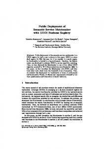
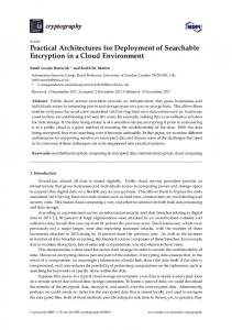
II. Experimental Setup Experimental data was recorded for two cases of carbon-fiber-composite tape springs. The first case involved individual springs in a two-dimensional deployment and the second involved three springs in a threedimensional tripod configuration. The precision and repeatability of the deployments in both cases was measured by On-Trak PSM2 10mm Position Sensing Detectors (PSD’s) shown in Figure 1. The PSM2 sensor is a single silicon photodiode 10mm on a side that provides an analog output of location of the centroid of the laser spot incident on its surface to a resolution of 250nm. Lasers were mounted directly to the ends of the tape springs in the twodimensional (2D) tests and to the simulated secondary mirror in the three-dimensional (3D) tests. Figure 2 shows solid-model representations of the test configurations, which were chosen to gain experience in a traceable geometry with testing the performance of the tape springs both as a single truss element and as a built-up structure. Both tests were conducted while mounted to a large 2.67x2.67x0.61m air-cushioned granite block to isolate the tests from ground vibrations.
Silicon Photodiode
Laser Spot
Figure 1 – On-Trak position sensing detectors (PSD’s) along with notional diagram Secondary Mirror Lasers Tape Springs Tape Spring Laser Path
PSD
PSD’s
Laser
Primary Mirror
(a) Two-dimensional configuration
(b) Three-dimensional tripod configuration
Figure 2 – Experiment configuration for 2D and 3D tests The tapes springs used the 2D test were selected to match the geometry of those in the 3D test, which was nominally based on the diameter-to-length ratio of a compact Cassegrain space-telescope design. The telescope
-2American Institute of Aeronautics and Astronautics
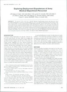
configuration here mimics the shape of a 0.3048m (12.00in) diameter primary mirror, a 0.1016m (4.00in) diameter secondary mirror, and a 0.3048m standoff distance of the secondary from the primary. In Figure 2(b), the geometries of the triangular plates at the mirror locations, labeled “secondary mirror” and “primary mirror” for simplicity, were determined by inscribing triangles in the 0.3048m and 0.1016m diameter circles representing the mirrors. This configuration dictated a tape-spring length of 0.3213m (12.65in). The tape springs, lasers, and sensors are all therefore attached to what would be the outer circumference of the primary or secondary mirrors. The geometry of this 3D test is not ideal as a direct application to telescope; rather, the geometry allows testing of fundamental structural elements with sensor geometry traceable to larger systems. Tape springs of the length, width, and curvature used in the 3D test were also used in the 2D test. Figure 3 shows images of the 2D and 3D tests. In the 3D testing configuration, the lasers were mechanically mounted on the secondary mirror, but in the 2D tests, they were attached directly to the tape springs. To fix the lasers to the tape spring, each laser was adhered to the tape spring and secured with a pressure fitting of aluminum tape. The aluminum tape was packed around the laser to minimize movement of the laser relative to the tape spring. The clamp configuration of Figure 3(a) indicates a difficulty of mounting the tape springs in the 2D configuration. A flat clamp across the entire width of the curved spring was impractical because it would flatten the portion of the spring in the clamp. When part of the spring is flattened, it has little transverse bending stiffness and is therefore too unstable for use in these experimental investigations. Curved clamps presented implementation difficulties. The optimum solution in this case was to clamp a small length of the tape spring over just a portion of the width, as shown in Figure 3(a). No slippage was observed over the several hours of test data taken following each bending event.
PSD Laser mount
Tape spring
Secondary mirror
Clamp Laser Tape spring (a) 2D test configuration
Actuated tape springs
Hinges Primary mirror
(c) 3D deployed test configuration
(b) 3D stowed test configuration
Figure 3 – Test configurations
-3American Institute of Aeronautics and Astronautics
Tape springs tend to snap back into their original shape after being folded. To reduce the possibility of loosening the laser, the tape springs in the 2D tests were guided slowly back to the deployed configuration by hand and thereby not allowed to snap. In the 3D tests the weight of the secondary mirror was sufficient to prevent the tape springs from returning to a straight (deployed) configuration without assistance. The secondary mirror was therefore also deployed manually to limit any snapping and accompanying shock loads that might alter the laser, spring, and sensor alignment.
III. Tape Spring Design and Manufacturing Instead of rolling the tape spring along its entire length as in a tape measure – clearly impractical based on the geometry shown in Figures 2(b), 3(b) and 3(c) – the springs used here are manufactured with hinges along their length to allow the tripod structure to be folded down, bringing the secondary mirror directly on top of the primary. The majority of each tape spring is comprised of two plies of woven, +45/-45 IM7-977 carbon-fiber composite with one or more hinges along its length l. Each hinge is 15mm in length, extends the entire width w of the spring, and is comprised of a single ply of IM7. The springs all have a radius of curvature, R, equal to the cylindrical mandrel on which they are cast and subtending 1/3 of the circumference of the circular cross-section (θ = 120°). When a tape spring bends, the radius of curvature of the bend, r, is equal to the radius R of the spring itself (see Figure 4). The analytic description of r = R can be found in Reference 1. l r w The carbon-fiber composite tolerates fairly high geometric strains, and so the 15mm length (lh) of the hinge is much less than the radius R of the spring (thus r