Available online at www.sciencedirect.com
ScienceDirect Physics Procedia 69 (2015) 491 – 495
10th World Conference on Neutron Radiography 5-10 October 2014
Design and characterization of a hydride-based hydrogen storage container for neutron imaging studies A. Baruja,b,c, M. Arditoa, J. Marínb*, F. Sáncheza,b, E.M. Borzonea,b, G. Meyera,b,c a
Instituto Balseiro, Univ. Nac. de Cuyo-CNEA, 8400 S.C. de Bariloche, Argentina b Centro Atómico Bariloche, CNEA, 8400 S.C. de Bariloche, Argentina c CONICET, Argentina
Abstract We have designed, constructed and tested a prototype hydride-based container to in-situ observe the hydride decomposition process using a neutron imaging facility. This work describes the container design parameters and the experimental setup used for the studies. The results open new possibilities for the application of the neutron imaging technique to visualize the internal state of massive hydride-based hydrogen containers, thus aiding in the design of efficient hydrogen storage tanks. © Published by Elsevier B.V.B.V. This is an open access article under the CC BY-NC-ND license © 2015 2015The TheAuthors. Authors. Published by Elsevier (http://creativecommons.org/licenses/by-nc-nd/4.0/). Selectionand andpeer-review peer-review under responsibility of Paul Scherrer Selection under responsibility of Paul Scherrer InstitutInstitut. Keywords: neutrography; neutron radiography; in-situ experiments; computer assisted modeling
1. Introduction Hydride forming materials (HFM) are promising candidates for hydrogen storage, compression and purification applications as presented, for example, in the review of Sakituna et al. (2007). Several HFM families are currently under research, being the most prominent those based in rare earth elements (AB5), in Mg (AB2) and in the Fe-Ti system (AB). The typical characterization of HFM involves determining the hydrogen storage capacity, equilibrium pressures at different temperatures, reaction kinetics and cycling stability. In most cases, material characterization is performed using small samples (10-100 mg), aggregated in the form of fine powders. However, real-life
* Corresponding author. Tel.: +54-294-444-5100; fax: +54-294-444-5199 E-mail address:
[email protected]
1875-3892 © 2015 The Authors. Published by Elsevier B.V. This is an open access article under the CC BY-NC-ND license (http://creativecommons.org/licenses/by-nc-nd/4.0/). Selection and peer-review under responsibility of Paul Scherrer Institut doi:10.1016/j.phpro.2015.07.069
492
A. Baruj et al. / Physics Procedia 69 (2015) 491 – 495
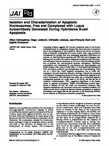
applications deal with large amounts of hydrogen and several kilograms of HFM are needed (see, for example, Au et al. 1996). The HFM is usually placed in large metal containers. The reaction enthalpy of HFM results in considerable material heating when it absorbs hydrogen and cooling when the hydride phase decomposes. As a consequence, the reaction kinetics of massive storage systems is more affected by overall thermal transfer than by the HFM intrinsic properties. Modeling the behavior of large systems is a difficult task largely affected by the container geometry, HFM placing, HFM powder compaction and the addition of heat transfer elements. Neutron imaging (NI) is a useful tool for analyzing massive HFM tanks due to the large neutron cross section of hydrogen in comparison to most HFM and structural tank materials (Pranzas et al. 2009, Bellosta von Colbe et al. 2012, Wood et al. 2014). In this work, we present the design and testing of a HFM tank specifically intended for NI experiments. The main objective is to introduce a device for obtaining reaction characteristics during the thermalinduced dehydriding stage that can be useful for modeling the behavior of real-life massive HFM hydrogen containers. 2. Device design The design of the storage device was performed considering several conditions. First, the device should contain enough HFM to make thermal effects (like thermal conductivity through the material) relevant for hydrogen intake and emission processes. Second, the resulting NI contrast has to be high enough to allow differentiating between hydrided and not hydrided zones. Third, the structural design should allow a working pressure range between 0 bar and 20 bar and a maximum temperature of 150ºC on the outside wall. Fourth, thermal conduction should proceed preferentially from a central heater, avoiding heat distribution by the metal walls as possible. Fifth, the container dimensions should allow it to be manipulated inside a glove box. In order to find the optimal thickness we performed a calculation based on the expected contrast between the HFM and the fully hydrided material using the transmittance equation T = I/I0 = exp (-σ·γ·χ/M), where σ is the total neutron cross section of the material, γ the material density (in g/cm3), χ is its thickness and M the atomic weight (in g/mol). The calculations were performed considering LaNi5 as HFM and LaNi5H6 as hydrided material. The result is displayed in Fig. 1(a) in terms of transmittance difference (contrast), showing that there is a maximum in the contrast curve for an HFM thickness interval between 13 mm and 15 mm.
Fig. 1. (a) Calculated contrast variation vs. thickness of HFM; (b) Calculated contrast variation for stainless steel lids and a combination of stainless steel (5 mm thickness) and aluminum lids.
On the other hand, the container should be able to stand pressure and temperature, and its material should not react with most HFM. A good choice would be 304L stainless steel. However, steel affects the image contrast. The dotted line in Fig. 1(b) represents the contrast variation as the steel thickness increases. A calculation of the thickness needed to withstand the design internal pressure based on the ASME standard Section VIII results in 13 mm which would be considerably detrimental for imaging purposes. A different approach to the problem consists in using thin steel lids and supplementing them with stronger Al lids in order to reach the required mechanical resistance. The solid line in Fig. 1(b) shows the effect on contrast of additional Al lids, considering that the HFM is encased between two 2.5 mm thick steel plates. Al is almost transparent for neutrons, which allows
A. Baruj et al. / Physics Procedia 69 (2015) 491 – 495
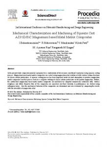
reaching good contrast values without compromising the structural stability of the container. Fig. 2(a) shows an exploded view of the designed device and Figs. 2(b) and 2(c) present photographs of it. The container is cylindrical with 88 mm of inner diameter and 125 mm of outer diameter. Its body was constructed in one piece of 304L stainless steel. The cylinder floor is 1 mm thick, and the internal height is 14 mm. The internal front lid is also made in 304L stainless steel but with a thickness of 3.2 mm in the central part and 1.4 mm in the outer part, which closes the cylinder by resting on a silicon o-ring. The total steel thickness in the path of neutrons is 4.2 mm. The cylinder is then encased between two Al lids, each 130 mm in diameter, being the front one 6.8 mm thick and the rear one 8.9 mm thick. A 1/4” stainless steel tube, inserted and welded to the side wall, acts as a hydrogen inlet/outlet. A 0.5 μm sintered stainless steel filter was placed on the inner side of this tube in order to prevent the escape of HFM particles from the container. The tube is closed by a Swagelok SS-42S4 valve. A Cu cylinder (external and internal diameters of 8.6 mm and 6.6 mm, respectively) was placed through the center of the container body floor in order to host a 100 W resistive cartridge heater. The container was subjected to a hydraulic test up to 30 bar, cleaned and filled with 200 g of commercial LaNi5 slumps (purity 99.9%, REacton). The slump decrepitates into fine powder after some activation cycles. In all subsequent experiments, the starting condition of the HFM was fully hydrided (LaNi5H6).
Fig. 2. (a) Exploded view of the container design. (b) Lateral view of the constructed device. The rear side is up in this image. (c) Rear view. The central cavity hosts the resistive heater.
3. Experiment description and results We were interested in performing an in-situ hydrogen desorption experiment, activated by the central resistive heater. The available neutron radiography experimental facility is located next to the biological shielding of the RA-6 experimental nuclear reactor of Centro Atómico Bariloche, Argentina. The neutron beam shape is a square of 20 cm × 20 cm at the sample position. By design, the ratio between the source to sample longitude (L) and beam aperture (D) is fixed to 100 (L/D = 100). At a reactor operation power of 500 kW, the neutron fluxes are 2.54 × 10⁶ n/cm2s (thermal) and 2.93 × 10⁴ n/cm2s (epithermal). The detection system consists of a 20 cm × 20 cm scintillation screen made of 6LiF/ZnS doped with Ag, made by Applied Scintillation Technologies The scintillation screen light peak is at λ = 450 nm. The light is reflected out of the beam path by a set of two front surface mirrors in order to protect the CCD camera from the incoming radiation. A Schneider Kreuznach Xenon condensing lens
493
494
A. Baruj et al. / Physics Procedia 69 (2015) 491 – 495
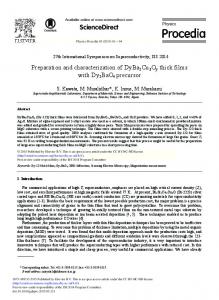
focuses the image onto the camera. Both, the lens and the camera are placed inside a light-tight box. The camera is a Penguin 600 CLM from Pixera Corporation. It has a maximum resolution of 2776 pixels × 2074 pixels and provides digital depth of 16 bits. The CCD dark current is reduced by a four stage thermoelectric Peltier cooling device. The main concern raised by the reactor safety officials was about handling hydrogen at high pressures in the facility. In fact, when a HFM is heated, its equilibrium pressure raises. In the case of LaNi5, it can exceed 60 bar at 150ºC. In order to avoid a buildup of hydrogen at high pressure, the container inlet/outlet was connected to a 50 l gas cylinder (proof pressure 300 bar) via a high pressure hose and a one-way valve, as shown in the schematic view presented in Fig. 3(a). The initial hydrogen pressure inside the gas cylinder was 2.5 bar, slightly above the equilibrium pressure of LaNi5 at room temperature. Then, upon being placed in contact, the container would not release hydrogen unless the central heater was powered. On the other hand, the hydrogen released during the experiment will be stored in the 50 l cylinder without the possibility of returning to the HFM container. During the experiment, the pressure in the gas line and the temperature of the central heater were constantly monitored. Threshold values were set at 5 bar for the pressure and 400ºC for the heater upon which the reactor would be shut down via scram and the experiment terminated. In addition, the air inside the NI chamber was being pumped out and monitored by using a hydrogen sniffer detector. Any positive detection on the pump exhaust would also trigger the reactor and experiment shut down. The actual experiment was first performed under laboratory conditions using an identical setup while all relevant parameters were measured by using a Sieverts-type volumetric equipment.
Fig. 3. (a) Schematic view of the experiment setup. (b)-(e) NI pictures taken at different stages of the experiment (0 min, 19 min, 35 min and 60 min, respectively).
Figs. 3(b) to 3(e) show pictures taken at different stages of the experiment. The heater power was constant at 60 W and the complete hydrogen desorption took about 1 h. The hydride phase decomposes from the center and a reaction front appears in the HFM. This result illustrates the possibilities offered by this new device for applying the NI technique to experimentally determining the desorption behavior of massive hydrogen storage container based on the use of HFM.
A. Baruj et al. / Physics Procedia 69 (2015) 491 – 495
4. Conclusions We have designed a container useful for in-situ studying the behavior of hydrogen storage materials in a neutron imaging facility. The computer assisted design took into account the neutron absorbance of the structural and hydrogen storage (LaNi5) materials in order to obtain a useful contrast between fully hydrated and fully dehydrated conditions. The container allows hydrogen exchange during the experiments and contains a central heater to perform heat-induced dehydrating studies. The container was successfully tested at the neutron imaging facility of RA-6 experimental nuclear reactor of Centro Atómico Bariloche, Argentina. The result show that this new device could help to experimentally determine the desorption behavior of massive hydrogen storage container based on the use of HFM. Acknowledgements The authors gratefully acknowledge S. Rivas, F. Roldán, J. Promet and G. Facchini for their assistance during container construction and experiment setup. This work has been funded by ANPCyT (PAE 36985 and PICT 20121796), U.N. Cuyo (Project 06/C417) and by ANPCyT-CNEA through fellowships from PFDT-PRH 200. JHM wishes to thank the IAEA and PSI for the financial support received to participate in WCNR-10. References Au, M., Chen, C., Ye, Z., Fang, T., Wu, J., Wang, O., 1996. The Recovery, Purification, Storage and Transport of Hydrogen Separated from Industrial Purge Gas by Means of Mobile Hydride Containers. International Journal of Hydrogen Energy 21, 33-37. Bellosta von Colbe, J.M., Metz, O., Lozano, G.A., Pranzas, P.K., Schmitz, H.W., Beckmann, F., Schreyer, A., Klassen, T., Dornheim, M., 2012. Behavior of scaled-up sodium alanate hydrogen storage tanks during sorption. International Journal of Hydrogen Energy 37, 2807-2811. Pranzas, P.K., Bösenberg, U., Karimi, F., Münning, M., Metz, O., Bonatto Minella, C., Schmitz, H-W., Beckmann, F., Vainio, U., Zajac, D., Welter, E., Jensen, T.R., Cerenius, Y., Bormann, R., Klassen, T., Dornheim, M., Schreyer, A., 2011. Characterization of Hydrogen Storage Materials and Systems with Photons and Neutrons. Advanced Engineering Materials 13, 730-736. Sakituna, B., Lamari-Darkrim, F., Hirscher, M., 2007. Metal Hydride Materials for Solid Hydrogen Storage: A Review. International Journal of Hydrogen Energy 32, 1121-1140. Wood, B.M., Ham, K., Hussey, D.S., Jacobson, D.L., Faridani, A., Kaestner, A., Vajo, J.J., Liu, P., Dobbins, T.A., Butler, L.G., 2014. Realtime observation of hydrogen absorption by LaNi5 with quasi-dynamic neutron tomography. Nuclear Instruments and Methods in Physics Research B 324,95-101.
495