Many inexpensive methods are readily available for editing digital data and, unlike .... Secret digital signatures identify the copyright ... embedded signature.
Design and evaluation of sparse Quantization Index Modulation watermarking schemes Bruno Cornelis, Joeri Barbarien, Ann Dooms, Adrian Munteanu, Jan Cornelis, Peter Schelkens a a Vrije
Universiteit Brussel - IBBT, Department ETRO, Pleinlaan 2, 1050 Brussels, Belgium ABSTRACT
In the past decade the use of digital data has increased significantly. The advantages of digital data are, amongst others, easy editing, fast, cheap and cross-platform distribution and compact storage. The most crucial disadvantages are the unauthorized copying and copyright issues, by which authors and license holders can suffer considerable financial losses. Many inexpensive methods are readily available for editing digital data and, unlike analog information, the reproduction in the digital case is simple and robust. Hence, there is great interest in developing technology that helps to protect the integrity of a digital work and the copyrights of its owners. Watermarking, which is the embedding of a signal (known as the watermark) into the original digital data, is one method that has been proposed for the protection of digital media elements such as audio, video and images. In this article, we examine watermarking schemes for still images, based on selective quantization of the coefficients of a wavelet transformed image, i.e. sparse quantization-index modulation (QIM) watermarking. Different grouping schemes for the wavelet coefficients are evaluated and experimentally verified for robustness against several attacks. Wavelet tree-based grouping schemes yield a slightly improved performance over block-based grouping schemes. Additionally, the impact of the deployment of error correction codes on the most promising configurations is examined. The utilization of BCH-codes (Bose, Ray-Chaudhuri, Hocquenghem) results in an improved robustness as long as the capacity of the error codes is not exceeded (cliff-effect). Keywords: image processing, DRM, (digital) watermarking, wavelet transform, quantization (QIM), Stirmark, error correcting codes
1. INTRODUCTION A famous example of classical watermarking is that of banknotes. If you hold the banknote up into the light, an image appears together with the value of that banknote. Such practices have existed for quite a long time (at least some centuries), but the field of digital watermarking has only gained widespread popularity as a research topic in the later half of the 1990s. Digital watermarking is the practice of hiding a message m, such as hidden copyright notices or other verification messages, in an image, audio clip, video clip, or other media. Such a message is a group of bits describing information pertaining to the signal or to the author of the signal (name, place, etc.). The digital content in which the message is embedded is called the coverwork or host signal s. This paper describes the design, implementation and evaluation of a quantization-based watermarking scheme for still images, which operates in the wavelet domain. Quantization-based watermarking schemes are currently regarded as the state-of-the-art in watermarking schemes where the host data does not interfere with the watermark decoding process. As a result, they outperform earlier techniques such as spread spectrum modulation 1 in terms of so-called fidelity/robustness-tradeoff. The properties of watermarking schemes and their applications are summarized in Sections 1.1-1.2. Section 2 explains the principles of quantization-based watermarking techniques. In the third section, the proposed treebased and block-based watermarking schemes are explained in detail. The tree-based technique embeds a single message bit into a set of coefficients belonging to the same wavelet-tree. The block-based technique embeds a single message bit in a rectangular block of wavelet coefficients. The conducted experiments are summarized in Section 4. An optimal result was obtained, where 70 bits are hidden in a 512 × 512 image with robustness against noise, compression, high-pass and low-pass filtering, while the image quality is only slightly affected.
Applications of Digital Image Processing XXXI, edited by Andrew G. Tescher, Proc. of SPIE Vol. 7073, 70731M, (2008) · 0277-786X/08/$18 · doi: 10.1117/12.796692
Proc. of SPIE Vol. 7073 70731M-1 2008 SPIE Digital Library -- Subscriber Archive Copy
1.1 Properties of watermarking systems Depending on the application, watermarking techniques can be subject to different constraints, including:2 • Fidelity/Transparency: The watermarked work should usually be perceptually similar to the original coverwork. Embedding of information should not cause perceptual degradation of the host signal. • Robustness: Robustness refers to the ability of the embedding algorithm to survive common signal processing operations. • Payload: Data payload refers to the number of message bits that can be embedded in the coverwork (e.g. the number of bits embedded in an image). • Security: This term refers to the ability to survive hostile attacks. These attacks are designed to remove the hidden information without loss of the perceptual quality. • Detectability: In some watermarking applications the very existence of message communication must stay concealed. In this case, the watermarking is a form of steganography, i.e. the message is hidden in the host signal without the end user’s knowledge.2 • Informed or blind detection: In some systems the unwatermarked work is available at the receiver side (informed detection). This can substantially improve the performance of the detector as the original host data can be subtracted from the watermarked image to obtain the watermark pattern alone. Systems that are in this category are often referred to as private watermarking systems. In other applications, the detection of the watermark has to be done without any information on the original work (blind detection). These applications are sometimes referred to as public watermarking systems.
1.2 Watermarking applications1 The most well known application of watermarking is probably copyright protection. Secret digital signatures identify the copyright holder and allow to prove ownership in a court of law. To avoid the malicious removal or altering of this information, the employed watermarking technique must be both robust and secure. Another application is called traitor tracing or fingerprinting. In this system documents are distributed with a distinct embedded signature. If an unauthorized use is detected, it can be traced back to the original owner. Large scale use of watermarks for traitor tracing is known to be vulnerable to collusion attacks, where multiple copies (usually no more than 20) of a single work are acquired, each with a different watermark, to obtain an approximation of the original unwatermarked work.3 Other possible applications of watermarking are: content authentication (Forgery Detection), media forensics, steganography, database annotation, in-band captioning, copy and device control, etc.
2. QUANTIZATION INDEX MODULATION (QIM) 1
In , one can find an historic overview and an excellent mathematical model of watermarking. The most recent data-hiding techniques, Quantization Index Modulation (QIM) watermarking (or sometimes called dither modulation 4 ), were introduced by Chen and Wornell in 19995 and embed a signal-dependent watermark in realvalued host data s. These schemes are related to work from the early 1980s in information theory by Costa.6 We have three main classes of QIM-schemes depending on the quantizer being used.
2.1 Scalar QIM Let Q be a uniform, scalar quantizer with stepsize ∆, i.e. for s ∈ R Q(s) = ∆�s/∆�. To embed one bit m in the real-valued sample s, we create two new quantizers Qm (m = 0, 1) from Q using ∆ d0 = − ∆ 4 and d1 = 4 , Qm (s) = Q(s − dm ) + dm . In this way, we obtain two cosets Λm of the lattice ∆Z, namely Λ0 = d0 + ∆Z and Λ1 = d1 + ∆Z.
Proc. of SPIE Vol. 7073 70731M-2
2.1.1 Original QIM The watermarked signal x is defined as � x=
Q0 (s) Q1 (s)
m=0 m = 1.
In fact, the watermark w is given by the quantization error |Qi (s) − s|. To decode the watermark message m, assuming that the QIM-watermarked signal x is corrupted by the attacker, resulting in the signal y = x + n, a minimum distance decoder is used, i.e. m � = argminm∈{0,1} (mins∈Λm |y − s|). The larger the stepsize ∆ is chosen, the more robust an image becomes to attacks, but the more the watermark becomes visible. 2.1.2 Distortion-Compensated QIM The fidelity/robustness-tradeoff of QIM-based watermarking schemes can further be improved in the following way. Given a host sample s, the distortion compensated scalar QIM embedding function is defined as � m=0 Q0 (αs) + (1 − α)s x= m = 1, Q1 (αs) + (1 − α)s where α ∈ [0, 1] is a parameter to be optimized. Note that for α = 1 this scheme reduces to original QIM. The decoder of the (attacked) watermarked signal y applies the original QIM decoder to αy. The advantages of the distortion-compensated QIM (sometimes called Scalar Costa Scheme 7 ) are so significant that it replaces the original QIM scheme in practice.
2.2 Sparse QIM Chen and Wornell5 extended the scalar QIM scheme to embed one bit in a length n host sequence s ∈ Rn and called it sparse QIM (or spread transform dither modulation (STDM)). This method consists of quantizing the projection of the host vector s along a chosen direction determined by a unit vector p. The coordinates of the host vector s are changed accordingly, resulting in the watermarked signal x � x=
s + (Q0 (�s, p�) − �s, p�)p s + (Q1 (�s, p�) − �s, p�)p
m=0 m = 1,
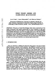
where �, � denotes the Euclidean inner product. Note that the distortion only takes place in the direction determined by p. The decoder projects the received data y onto Rp and decides whether quantizer Q0 or Q1 was used. Hence we apply the original QIM decoder to �y, p�. Let us give an example in R2 . In Figure 1 the vector s is projected on the line Rp defined by p. To embed the bit m = 1, the projection gets mapped to the closest quantization value on Rp corresponding to the message m = 1. The watermarked vector x is now equal to s + w, where w = (Q1 (�s, p�) − �s, p�)p. There exist several extensions and refinements of this sparse QIM method; in particular one can define a distortion-compensated variant.
2.3 Lattice QIM Chen and Wornell presented a second extension of the scalar QIM scheme to embed a binary vector of length n in a host sequence s ∈ Rn . The idea is to replace the scalar quantizer with an n-dimensional vector quantizer. This technique was not used during experiments.
Proc. of SPIE Vol. 7073 70731M-3
Si
Figure 1. Two-dimensional sparse QIM example.
3. METHODS As stated in the introduction, the proposed watermarking schemes embed information in the wavelet domain (using 9.7 biorthogonal wavelet filters). As the wavelet transform is a frequency decomposition, wavelet-based watermarking schemes can choose to embed the message in the wavelet coefficients according to the frequency range. For instance, high-frequency coefficients can be excluded from the embedding process since they are very sensitive to image compression and low-pass filtering. On the other hand, low-frequency coefficients can be excluded since changing these coefficients is visually more perceptible than changing high-frequency coefficients. We will combine n wavelet coefficients to form the host vector s in n-dimensional real space. The way the wavelet coefficients are grouped to form a vector is the main difference between the two watermarking schemes proposed hereafter.
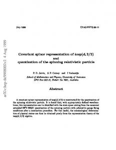
3.1 Tree-based technique Given an N -level wavelet decomposition, we can use coefficients in the same wavelet tree to form a vector of length n in which a single message bit is embedded using sparse QIM. As each wavelet tree starts with one coefficient in one of the detail subbands of the highest wavelet decomposition level (thus level N ) and includes all coefficients �Nat corresponding positions in the same subband of the lower decomposition levels, we have that n is at most i=1 22(N −i) . This is illustrated in Figure 2, where a three-level wavelet decomposition is employed. Hence we can choose the vector s to consist of twenty-one components (one for the third level, four for the second level and sixteen for the first level). 3.1.1 Parameters The properties (fidelity, robustness and payload) of the proposed watermarking system are influenced by several parameters, including the quantization step size ∆, the unit vector p used in the sparse QIM and the number of wavelet decomposition levels N . ∆: Larger quantization step sizes cause larger distortions in the image after the inverse wavelet transform is performed, but also increase robustness since a larger amount of noise can be added by attacks/image processing algorithms before the sample value falls into a neighboring quantization bin causing the message bit to be wrongly decoded. Furthermore, the same quantization step size is applied for each wavelet tree, but can differ on the levels within the tree for reasons explained below. p: The unit vector p can be chosen in an effort to reduce the perceptibility of the watermark; higher frequency coefficients can be quantized with a larger step size than those in middle frequencies (perceptual quantization). This can be accomplished by making the coordinates of p corresponding to these coefficients larger. In this way, the visual distortion is smaller than when the same global quantization stepsize is employed. A practical system can for instance be obtained by taking into account visual weights (as recommended in the JPEG2000 compression standard to minimize the perceptibility of quantization errors due to lossy wavelet compression) to construct the unit vector.
Proc. of SPIE Vol. 7073 70731M-4
LL —
I,
Ni
c-fl
0)
H
)b ••
..
>0 >0
512
512
(a) Tree-based method
(b) Block-based method
Figure 2. Three-level wavelet decomposition (N=3) of a 512 × 512 image.
N : The number of decomposition levels N directly influences both the fidelity/robustness-tradeoff and the payload of the watermarking scheme. �N 2·(N −i) coefficients. This When using N decomposition levels, each message bit is embedded in i=1 2 means that, the more decomposition levels are used, the higher the robustness of the scheme as more sample values are used to embed a single message bit. Given an image with dimension W ×H, the payload (number of possible wavelet trees) of the watermarking system can be calculated as: � � �� �� H −1 W −1 × · M bits, (1) 2N 2N where M is the number of wavelet subbands used for embedding. Note that we subtract width W and height H by 1 to avoid problems when the wavelet decomposition is performed on images of odd width and/or height. It follows from this equation, that the payload decreases as the number of wavelet decomposition levels raises. For a three-level wavelet decomposition applied on a 512 × 512 image the payload is 11907 bits (N = 3, M = 3); for a five-level decomposition the total payload is reduced to 675 bits (N = 5, M = 3).
3.2 Block-based technique The wavelet-transformed image is divided into blocks of w × h coefficients (see Figure 2). Sparse QIM is then used to embed a single message bit into each of these rectangular groups of coefficients. 3.2.1 Parameters The fidelity, robustness and payload are again influenced by several parameters, including the quantization step size ∆, the unit vector p, the employed block size B and the number of wavelet decomposition levels N . ∆: In our implementation, the quantization step size can be chosen in two different ways. The first possibility is to use ∆ for each block of w × h coefficients. The second possibility is to apply a larger quantization step size to blocks with high frequency coefficients using visual weights as explained in Section 3.1.
Proc. of SPIE Vol. 7073 70731M-5
p: For this scheme, we choose a diagonal unit vector as every coefficient in the w × h block typically belongs to the same subband of the same level in the wavelet decomposition and is thus of roughly equal importance for the visual quality. B: The size B of the coefficient blocks has an influence on both the fidelity and robustness of the watermarking scheme. Given an image with dimensions W × H and a chosen block size of w × h, the payload of the watermarking scheme is: � � �� � �� N ��� � W H 1 1 · · · · M bits, 2i w 2i h i=1
(2)
where N is the number of wavelet decomposition levels and M is the number of subbands used for embedding. For a five-level wavelet decomposition of a 512 × 512 image and a block size of 8 × 8 the total payload is 4092 bits. Increasing the block size decreases the payload of the watermarking scheme, as can be seen in Equation (2). The block size has an influence on the robustness as well. The larger the block size, the more robust the scheme becomes as more wavelet coefficients are used to embed one message bit.
4. EXPERIMENTS In order to test the performance of the two proposed watermarking schemes, we used the Stirmark Benchmark tool∗ . This tool tests the robustness of the watermarking schemes against attacks and/or standard image processing operations. It also measures the visual degradation due to the embedding of information in the image. The robustness of the used watermarking technique is expressed by counting the bit errors after decoding an attacked watermarked image. The bit-error rate (BER) is defined as the number of erroneously decoded message bits divided by the total number of message bits. The visual degradation (fidelity), caused by the watermark itself, is measured by the PSNR† . With each experiment the fidelity against the robustness is measured. The attacks on the watermarking schemes are JPEG compression, Addition of noise, Median filtering, Low-pass (Gaussian) filtering and Unsharp masking. The test images are all 512 × 512 natural grayscale images. The first part of each experiment describes bit errors for different embedding strengths‡ to allow us to determine the smallest embedding strength enabling error-free message extraction in the absence of attacks. When attacks are considered, the number of bit errors after the attack is measured for different embedding strengths of the watermark. A first series of experiments tests the robustness of the tree-based technique against all the attacks mentioned above. The more wavelet decomposition levels, the larger the number of wavelet coefficients are taken together to form a tree structure. This also means that more coefficients are used to encode one bit. The usage of the higher frequency wavelet levels has a negative effect. Most of the attacks have a bigger influence on the higher frequencies and cause more bit errors when decoding. The vector p is chosen either with equal coordinates, or with unequal coordinates by taking into account the higher sensitivity of HVS to changes in the lower frequency ranges. The second main part of the experiments tests the block-based scheme, where an obvious parameter is the blocksize. The larger the blocks, the more wavelet coefficients are used to encode one information bit and the more robust the scheme becomes. The downside in choosing a large blocksize is that the payload becomes smaller. The vector p is always chosen with equal coefficients because each wavelet coefficient belongs to the same subband in the same wavelet level. What can be chosen is the stepsize according to the subband in the wavelet ∗
http://www.petitcolas.net/fabien/watermarking/stirmark/ For the calculation of the PSNR, Stirmark compares the original image with the watermarked image in the spatial domain. ‡ For orthogonal wavelet transforms the relation between PSNR and embedding strength is given by P SN R = 60 − 20.log10 (embedding strength). For biorthogonal wavelet transforms the equation becomes an approximation.8 †
Proc. of SPIE Vol. 7073 70731M-6
decomposition. Just as with the tree-based technique the step sizes in the higher frequencies are larger. Here too, it became obvious that not using the high frequency subbands produces much better results in robustness. An important series of experiments consists of comparing both schemes. To be able to do this in a fair way, we use the same number of coefficients to embed each message bit in both cases. From Figures 3 and 4, it can be observed that the tree-based technique performs better than the block-based one. For the light compression attack (JPEG 90) the difference is rather pronounced but for the heavier compression (JPEG 40) the difference is less visible. In Figure 5 the mean BER over all images at all embedding strengths (except the lowest embedding strength values which do not allow reconstruction in the absence of errors) is shown for each considered value of the strength parameter. The result shows that the mean BER values are slightly but systematically lower for the tree-based compared to the block-based technique.
JPEG (90)
JPEG (90) 0.6 —
0.6
—.— Boot .
0.55 0.5
0.35 0.3
Lena .
0.55 —.—Barbara
Leno
040
P,pp,ro .
045 0.4
—.—— Boat .
Brbr
Peppers
0.4
035
LU 0.3 LU
0.25
0.25
0.2
0.2
0.15
015
0_I
0.
.
0.05
25
30
35
40
45
:T.."::II'IIIII'::"IIII:: 50
55
PSNR
PSNR (dB)
(a) Tree-based method
(b) Block-based method
Figure 3. Scheme comparison: JPEG compression
JPEG (40)
JPEG (40) 0.6 —
0.6 _____________
065 -—Earnara
0.05 - —.--Barbara
-
0.5 - —a—Boat
5.45 -
0.4 -
-
I
Peppers
0.35
-
0.25
-7
0.2 --0.15
Lena Pep;:-ers
04 035
•.
LU 0.3 LU
05 —.—Eoao 045
Lena
0-3
---
0.25
-. -
--a
02
....:t
5.15
u-----
*
::m-
01
TTT
0.1
.-:c!....
ji
5.05
0.05
20
30
35
40
50
45
55
20
30
PSNR
40
3'S
4'S
50
55
PSNR
(a) Tree-based method
(b) Block-based method
Figure 4. Scheme comparison: JPEG compression
The schemes were not only compared in case of the JPEG compression attack but also for all the other attacks mentioned earlier. Some results are shown in Figure 6 for median filtering and in Figure 7 for unsharp masking. Since the tree-based scheme performs better in most of the experiments, we continue further testing with the
Proc. of SPIE Vol. 7073 70731M-7
0.35
________________
N
0.3 •"v
0.05
________
0
40 80 60 JPEG compression
20
90
Figure 5. Scheme comparison (JPEG compression): Mean BER
Median
Median 0.5
0.56
0.55
0.5
0.5 .
0.45
0.25 . ___ Barbara .
O35
0.2
015
0.45 0.4
0.36 0.3
6.25 0.2
—a—Barbara
Baa
oi 0.05
0.05•
Pappars 25
30
—a-—Boat
0.1
LBnB
35
40 PSNR (dB)
45
53
Lena
Pe5prB
55
PSNR (dB)
(a) Tree-based method
(b) Block-based method
Figure 6. Scheme comparison: Median filtering
Unsharp
Unsharp 0.0 ______________ 005 - —a— Barbara
-
05
045 04
Lena
Peppers
035 0.3
025
"i":"*—
:_.- .a—_j 615
-
o.r
0_i
-
005
U 55
20
30
30
40 40 PSNR (dB)
50
50
25
30
40
36
46
PSNR (dB)
(a) Tree-based method
(b) Block-based method
Figure 7. Scheme comparison: Unsharp masking
Proc. of SPIE Vol. 7073 70731M-8
50
65
tree-based scheme. A number of improvements were taken into account: the further reduction of high frequency DWT levels used for embedding, distortion compensation and the usage of error correcting.
4.1 Omitting DWT levels for embedding As stated earlier, the usage of the higher frequency wavelet levels has a negative effect. That’s why some experiments were taken where the two first wavelet levels are not used for embedding. As can be seen in Figure 8 the difference with the first experiment, where all levels are used for embedding, is substantial.
JPEG (20)
JPEG (20)
0.5
0.5
0.55
0.45
I.
045
04 0.35
035
0.3
02
0.25
025
0.2
02
0.15
0 IS
—.—Brrr
005
L.rnr
—'—Boat Lena
/1
0.1
Sarsara
Si
—..— Barbara
IIIIIIIIIIIIIIIIIIII
0.05
Pr pp rrs
25
30
35
43
45
50
55
PSNR
PSNR
(a) 5 DWT levels used for embedding
(b) 3 DWT levels used for embedding
Figure 8. Omitting DWT levels: JPEG compression
4.2 Distortion compensation Another improvement that was tested is distortion compensation (mentioned in Section 2.1.2), where α is the important parameter. The optimal choice of α depends on the strength and type of attack. For the median filter, the scheme performs irrespective of the value chosen for α.
4.3 Error correcting codes (ECC)9 By using ECC to protect the message bits, some bit-errors can be corrected, thereby improving the robustness of the watermarking scheme at the expense of a reduced payload. For this purpose, we implemented BCH error correcting codes in the two watermarking schemes, using the IT++ package§ . A problem with the IT++ implementation of BCH codes is that it uses non-systematic coding instead of systematic codes, where the transmitter sends the original data bits followed by check bits (or redundant bits). In a system that uses a non-systematic code, data bits are transformed into code bits. If the number of errors exceeds the number that the code can correct, the decoder will output a series of zeros instead of the erroneous data bits. The latter bits, although some of them may be wrong, are still probably a better approximation of the original message bits and using them would likely lead to a reduced BER. This means that if errors become too numerous, we cannot separate code bits from data bits to get a better approximation of the original data bits, causing a worse BER. This problem could be solved using systematic encoding.9 A number of polynomials, each with different properties, have been used during the experiments.8 Applying BCH forward error correcting coding to the message bits unfortunately brings less performance gain than expected. In general, the performance when using these codes is worse than without using them. However, for weak attacks, which cause the watermark extraction process to produce only few bit-errors, using error correction codes does bring a significant improvement of the performance. For stronger attacks the number of bit-errors produced by the watermark extraction simply exceeds the capacity of the codes and the BCH decoding fails, §
http://itpp.sourceforge.net/current/index.html
Proc. of SPIE Vol. 7073 70731M-9
yielding poor performance results. This can be seen in the charts of Figure 9. For embedding strengths that result in not too densely packed bit errors, the BER is reduced further. On the other hand, the values where there are a substantial amount of bit errors, the BER increases drastically.
Noise (1) 3.55- -
Noise (1)
__________
055 _____________ —.—Barbara Boat 045 Lena
barbara
brat
b
045
04-
04
Peppars
035
0.35
U
03
02
025
025 0,2
0.2
.4-. ua
0_Is
015
25
U_I
0-20
.4
30
35
45
45
55
55
00
30
33
40
40
50
55
PSNR (dB)
PSNR
(a) No ECC
(b) ECC
Figure 9. Using BCH error correcting codes
4.4 Final experiment The final experiment is based on the conclusions that were taken from all previous tests: • The tree-based technique is used since it is slightly better than the block-based one. • We use a five-level wavelet decomposition, but only use the 2 lowest frequency subbands to embed the information (no embedding in the higher frequencies). • Distortion compensation is used with an α of 0.9 that seemed to be optimal for previous experiments. • A very strong error correcting code which should correct 24% of bit errors is used. All attacks were applied on watermarked images embedded with different strengths. The results are quite satisfying. By looking for the embedding strength that is robust to most of the attacks, an embedding PSNR of about 43.5dB is the maximum value that can be obtained without significant decrease of fidelity. Otherwise, if we do not consider the median filter and the very strong compression attacks, a PSNR of 48dB is reachable. The visual result of the embedding is shown in Figure 10. One can see that for an embedding of 43.5dB the watermark becomes visible.
5. CONCLUSIONS State-of-the-art quantization-based watermarking schemes have been tested and compared. 1. There is not much difference between the results of the proposed tree-based and block-based watermarking schemes. The tree-based one performs slightly better than the block-based one. 2. It is clear that, while a large number of wavelet decomposition levels is preferable, embedding only in the detail subbands of the higher levels yields the best performance. This is especially the case with attacks that influence the high frequency components of an image (e.g. median, Gaussian, unsharp masking filters and JPEG compression). Removal of the first, second and even the third-level of the five-level wavelet decompositions from the embedding process significantly increases the performance. This means that most of the wavelet coefficients are not used for embedding and hence the robustness against attacks decreases. The addition of noise is the only exception: using more coefficients makes the scheme more robust. However,
Proc. of SPIE Vol. 7073 70731M-10
3.
4.
5.
6.
the improved robustness against filtering and compression attacks, is much more important than the slightly diminished robustness to noise. Note that the robustness of the watermarking remains unchanged under resolution scaling by dropping wavelet decomposition levels when it is limited to the levels that are not used for embedding the watermark. When using perceptual quantization in the watermarking process, the watermark becomes less visible to the human eye, as expected. Unfortunately, the robustness of the watermarking scheme seems to deteriorate. This could be partially explained by the fact that we assess the robustness in function of the PSNR after embedding and that the PSNR decreases when using non-uniform quantization as opposed to uniform quantization, since uniform quantization is theoretically seen as the optimal solution to minimize the mean square distortion. However, the reduced robustness is also observed in an subjective visual test. The use of distortion compensation also improves the results. However, some experiments show that it is important to find a good balance of the parameter α. The results show that an α of about 0.8 or 0.9 indeed performs better than the original watermarking scheme. Error correction coding of the message bits improves the results in cases where the number of bit-errors after watermark extraction does not exceed the code capacity. In other cases the forward error correcting codes lose their effectiveness. The last experiment shows that it is possible to produce a very robust watermarking scheme with good fidelity. This does not mean that the scheme is robust to every attack. It is important to note that stronger filters could completely destroy the watermark (especially in cases where error correction is used), but a stronger attack also means a more severe distortion of the image. In this case, the image can become useless and hence survival of the watermark becomes less important.
REFERENCES [1] Moulin, P. and Koetter, R., “Data-hiding codes,” Proceedings of the IEEE , 2083–2126 (October 2004). [2] Cox, I. J., Miller, M. L., and Bloom, J. A., [Digital Watermarking], Morgan Kaufmann (2002). [3] Cox, I. J. and Miller, M. L., “Electronic watermarking: the first 50 years,” IEEE Fourth Workshop on Multimedia Signal Processing , 225–230 (2001). [4] Chen, B. and Wornell, G. W., “Dither modulation: a new approach to digital watermarking and information embedding,” Proceedings of SPIE: Security and Watermarking of Multimedia Contents 3657, 342–353 (1999). [5] Chen, B. and Wornell, G. W., “Quantization index modulation: A class of provably good methods for digital watermarking and information embedding,” IEEE transaction on Information Theory , 1423–1443 (2001). [6] Costa, M. H. M., “Writing on dirty paper,” IEEE transaction on Information Theory , 439–441 (1983). [7] Eggers, J. J., Bauml, R., Tzschoppe, R., and Girod, B., “Scalar costa scheme for information embedding,” IEEE transaction on Signal Processing , 1003–1019 (2003). [8] Cornelis, B., Quantization-based watermarking, Master’s thesis, Vrije Universiteit Brussel, Department of Electronics and Information Processing (ETRO) (May 2007). [9] Lin, S. and Costello, D. J., [Error Control Coding-Fundamentals and Applications], Pearson, Prentice Hall (2004).
Proc. of SPIE Vol. 7073 70731M-11
L
SL r
(a) Original
L
r
(b) Embedding PSNR: 48dB
r
(c) Embedding PSNR: 43.5dB
Figure 10. Final experiment: visual comparison.
Proc. of SPIE Vol. 7073 70731M-12