Energies 2015, 8, 8001-8019; doi:10.3390/en8088001 OPEN ACCESS
energies ISSN 1996-1073 www.mdpi.com/journal/energies Article
Design and Experimental Study of a VCM-Based Stewart Parallel Mechanism Used for Active Vibration Isolation Weichao Chi, Dengqing Cao *, Dongwei Wang, Jie Tang, Yifan Nie and Wenhu Huang School of Astronautics, Harbin Institute of Technology, PO Box 137, Harbin 150001, China; E-Mails:
[email protected] (W.C.);
[email protected] (D.W.);
[email protected] (J.T.);
[email protected] (Y.N.);
[email protected] (W.H.) * Author to whom correspondence should be addressed; E-Mail:
[email protected]; Tel./Fax: +86-451-8641-4479. Academic Editor: Paul D. Ronney Received: 9 April 2015 / Accepted: 20 July 2015 / Published: 31 July 2015
Abstract: This paper presents the design and experimental study of a voice coil motor (VCM)-based Stewart platform used for active vibration isolation. The high precision payloads carried on the satellites always require an extremely stable environment to work properly. Installing a vibration isolation device between the vibration sources and precision payloads is an efficient method for dissipating vibration energy. A Stewart platform with active damping is designed to isolate the vibration transferring from the satellite to the payloads in six degrees-of-freedom. First, the kinematics and dynamical equations of a Stewart platform with spherical joints at both the base and top of each leg are established with Newton-Euler Method in task space and joint space. Second, the H∞ Control Theory is employed to design a robust controller for the linearized system with parameter uncertainty, noise and sensor errors. Finally, an experimentation study on the vibration of the payload supported by a Stewart platform with VCM actuator is conducted. The feasibility and effectiveness of the vibration isolation system are verified by comparing the amplitude-frequency characteristics of the active control system with that of the passive control system and the system without damping. Keywords: vibration isolation; Stewart platform; VCM actuator; Newton-Euler Method; H∞ control; sinusoidal sweeping analysis
Energies 2015, 8
8002
1. Introduction In aerospace engineering, an extremely stable environment is increasingly desired to ensure high precision payloads such as cameras, telescopes, interferometers and laser communicators etc. carried on satellites can work properly. Any small amount of undesirable disturbance may cause a deviation from the required state and significantly affect the accuracy of the payloads. For instance, a slight vibration of a satellite camera may seriously blur the image. Meanwhile, satellites always carry several vibration sources such as reaction wheels, solar array drives and cryo-coolers, etc. Under such conditions vibration isolation systems which are fixed between the vibration sources and precision payloads to prevent the transmission of vibrations have become critical components. Passive damping methods are widely used in the vibration isolation of structures due to the reliability and lower cost of a passive device. They consist of mass-spring-damper systems whose parameters are adjusted for the whole structure and do not need a power input. Traditional linear passive isolation performs well for high-frequency band attenuation, but may be limited in the low-frequency band because the stiffness of the isolation system cannot be unrestrainedly soft, that is to say the natural frequencies of the structure may coincide with some frequencies of disturbance which will lead to a vibration amplification. Employing a nonlinear passive isolator may be a practical way to overcome the vibration amplification problem in traditional linear passive isolation (see the study on the resonant responses of a nonlinear oscillator under harmonic excitations in [1,2]). As an effective way of reducing vibration transmission, active isolation has been studied and applied in practical engineering in recent years. Active vibration isolation provides significant performance enhancements over passive methods for the active actuators can provide suitable force which varies with the sensor’s feedback in real time to control the movement state of the system. With the development of sensor, actuator and microprocessor technology, active vibration isolation has become a more practical approach and has been widely used in ground to aerospace applications in the past decade. Fuller et al., discussed various control strategies including feedforward and feedback concepts for vibration isolation systems [3]. Preumont et al., analyzed the difference between force feedback and acceleration feedback of a skyhook damper by the root locus method [4]. As an important component of an active vibration control system, the actuator provides a control force to the structure. There are several types of actuators for active vibration control: piezoelectric actuator, pneumatic spring and electro-magnetic actuators etc., all of these actuators are commonly used in vibration isolation systems. The choice of actuator depends on the amount of control force or moment, displacement, frequency response, power supply, dimensional constraints and mounting requirements, etc. Although the piezoelectric actuator (PZT) can work over a wide bandwidth and with high resolution, its working displacement (several millimeters) is too small. Pneumatic springs can provide a very large control force, but the response speed is not fast enough, and its associated mass is a disadvantage which cannot be avoided. Voice coil motor (VCM) is a type of electro-magnetic actuator which converts electric energy into mechanical energy [5]. As a kind of linear motor, a voice coil actuator has many good features as it can generate force with high accuracy and acceleration over a sufficient range of movement [6]. Park et al., developed a four-mount active vibration isolation system using voice coil actuators and presented a comparative study between decentralized and centralized control methods [7]. Kim et al., built a six-axis active vibration isolation system using a phase compensated velocity
Energies 2015, 8
8003
sensor [8]. Kerber et al., used eight voice-coil actuators to build a six degree-of-freedom (DOF) anti-vibration system and compared the results of PI controller, velocity feedback, state feedback and output feedback [9]. Chi et al., analyzed the application of VCM actuator in active vibration isolation for whole-spacecraft [10]. All of these applications have shown the feasibility and significant effectiveness of VCMs used as the actuator of active vibration isolation systems. To fully isolate the rigid body from the vibration source in multiple DOF, many forms of smart structure with build-in actuators have been studied. In 1965, Stewart proposed a six DOF parallel mechanism as a flight simulator, which was later named the Stewart platform [11]. A general Stewart platform has six extensible legs connecting the base-platform and the payload-platform through joints at the ends of each leg as shown in Figure 1. One of the most widely used type of the Stewart platform is the 6-UPS platform of which the upper and under joints are universal joint and spherical joint, respectively. The Stewart platform has been studied widely in basic fields such as flight simulation, mechanical machining, precision positioning and vibration isolation. Payload Platform
Joint
Extensible Leg Base Platform
Figure 1. A classical Stewart structure. Fichter [12] and Bonev [13] presented methods for solving the kinematics problem of a general Stewart platform without considering the moment of inertia. Lebert et al., built dynamic formulations of a Stewart platform through a Lagrange approach [14]. Dasgupta et al., established the inverse dynamic and the closed-form dynamic equations of the general Stewart platform through the Newton-Euler approach [15,16]. McInroy et al., formulated a flexure jointed hexapod in which the vibrations of the base platform are considered to be one part of the whole dynamic system in the micro-motion case of the upper platform [17]. Mukherjee et al., proposed a dynamic stability index of a flexible manipulator illustrated by considering the 6-UPS Stewart platform as an example [18]. Preumont et al., reported a six-axis vibration isolator consists of VCM actuators for space applications using decentralized control on each leg [19]. Xu et al., developed a closed-form dynamic model of a Stewart platform considering the external excitations on the base platform and designed the PD control law [20]. In this paper, we will focus on an active Stewart platform based on the VCM for isolating the vibration in the range from 5 to 100 Hz in six DOF. First, the dynamical equations of the payload supported by the Stewart platform are established with Newton-Euler Method in task space and joint space, respectively, and transformed into a state space model for the design of active vibration controller. Second, based on the H∞ control theory, a robust control strategy is presented for the linearized system with parameter uncertainty, noise and sensor errors. Finally, a Stewart platform with six VCM-based
Energies 2015, 8
8004
extensible legs is constructed with spherical joint connections, and an experimental device is set up for a payload supported by the Stewart platform. In the vibration test, the payload is vibrated by a shaker table located at the bottom of the Stewart platform. The active control force is determined by the proposed control law and performed by a Space real-time control system according to the acceleration response of the legs as feedback. The amplitude-frequency curves measured from the experiment on the active control system are utilized to verify the feasibility and effectiveness of the vibration isolator proposed here. 2. Kinematics and Dynamics Analysis of the Stewart Platform A general Stewart platform has six extensible legs connecting the base platform and the payload platform through joints at the ends of each legs. One of the most widely used types of Stewart platform is the 6-UPS platform of which the upper and under joints are universal joints and spherical joints, respectively. In this section, the kinematics and dynamics equations of a Stewart platform are established with the Newton-Euler Method in task space for a Stewart platform with spherical joints at both the base and top of each leg for the purpose of fully isolating the payload (a rigid body) from the vibration source in multiple DOFs. 2.1. Coordinate Transformation Define the inertial frame O and local frame B, P, D and U as shown in Figure 2. The coordinate frames B and P are attached to the base and the payload, whose origins are the mass center of the base and the payload, respectively. The coordinate frames U and D are attached to the upper and lower legs, respectively. U
pi P
rui tpi
li
tp tb O
B
bi
tbi
rdi D
Figure 2. Definition of coordinate frames and the model of one leg. The rotation of the payload is described with Cardan angles in sequence of rotation axes x-y-z by angles ψ , β , . The rotation matrix from the local frames B and P to the inertial frame can be given by:
R OB R OP Rot (x, ψ) Rot ( y,β) Rot ( z, ) cβ c cβs c s sψsβc cψ c γ sψsβs s s cψsβc cψsβs sψc
sβ sψcβ cψcβ
(1)
Energies 2015, 8 where c cos
,
8005
s sin
.
The transformation matrix from the local frame U and D to the inertial frame O is:
TUiO TDiO xi
yi
zi
(2)
where xi τi is the unit vector in the direction of the leg, yi and zi are defined in terms of a unit vector
k i as yi xi k i and zi yi xi / yi xi , respectively. The relationships between the vector in the inertial frame and the local vector can be expressed as: p Oi R OP p iP O O B b i R B b i rO RO r P P i i
(3)
where p iP and p Oi are the vectors of upper joint of ith leg in frame P and the inertial frame, respectively; b iB and B Oi are the vectors of lower joint of ith leg in in frame B and the inertial frame, respectively; riP and riO are the vectors of center of mass of payload in frame P and the inertial frame, respectively.
The relationships between the moment of inertia in the inertial frame and local moment of inertia can be expressed as: I OP R OP I PP R OP T O O D OT I di TDi I di TDi I O T O IU T O T Ui ui Ui ui
(4)
where I PP and I OP are the moment of inertia of payload in frame P and the inertial frame, respectively; I diD and I Odi are the moment of inertia of ith lower leg in frame D and the inertial frame, respectively; I uiD and I Oui are the moment of inertia of ith upper leg in frame D and the inertial frame, respectively.
2.2. Kinematics and Dynamics of a Leg As illustrated in Figure 2, the positions of frame P and B are described by position vectors t p and t b , respectively. The position vectors of upper and lower ends of a leg in the inertial frame O are: t pi t p pi
(5)
t bi t b bi
(6)
The vector of the leg line can be derived from the subtraction of t pi and t bi as: l i t pi t bi t p p i t b b i
(7)
and the acceleration of the upper and lower ends of the leg can be expressed as: t pi t p ω p ω p p i α p p i t bi t b ωb ωb b i α b b i
(8)
where α p , α b are the acceleration vectors of the payload and the base, ω p and ωb are the angular velocity of payload and the base, respectively. Then the velocity and acceleration of the leg are:
Energies 2015, 8
8006 li τ iT
l τ T i i
T tp p τ i i τ iT ω p
pi τi
T
t p τ iT αp
t b ω b
(9)
t b η1i τ i α b
(10)
bi τ i
bi τ i
T
T
where η1i is a higher order indefinite small variable which could be omitted. The force vector F between the upper and the lower legs, including the elastic restoring force and viscous damping from the spring-damper system and the active control force, can be written as: F K (l l 0 ) Cl Fa
(11)
where F F1 F6 , l l1 l6 . Fa Fa1 Fa 6 is the active control force vector, T
T
T
K diag k1 k6 , C diag c p1 c p 6 are the stiffness and damping matrices, respectively. From Equation (9), we have: r l H T p H T rb p b ω b ω p
(12)
where: τ6 τ6 τ τ , Hb 1 Hp 1 p1 τ1 p 6 τ 6 b1 τ1 b 6 τ 6
Taking the variation of the length of the ith leg as δli , then we have from Equation (12) that:
δrp δr δl l l 0 H Tp HbT b δθb δθ p Thus, we can obtain from Equation (11) that: δrp r p δr r F K (H Tp H bT b ) CH Tp CH bT b Fa δθb ω b δθ p ω p
(13)
2.3. Dynamical Equations of the Payload The forces and torques acting on the payload are shown in Figure 3 where M p is the mass of the top platform, and the vectors Fw and M w are total external force and torque, respectively. Fw
-Mpap Mw r Fui
O Mp g
Figure 3. The force analysis of the top platform.
Energies 2015, 8
8007
The position vector of the mass center is: r =R p r0
(14)
The dynamical evolution of the payload is governed by the Newton’s dynamical law as: 6
M p g Fw Fui M p a p
(15)
i 1
where the acceleration of the mass center is: a p =t p α p r +ω p ω p r
(16)
According to the Euler equation, the moment balance equation of control force and inertia force is: 6
6
i 1
i 1
p i Fui fi M w M p r g I*p α p ω p I*p ω p
(17)
* where I p is the moment of translating I p to mass center of figure which has a relationship with
the moment of inertia to mass center I p as: I *p I p M p r T rE3 rr T
(18)
Equations (11), (15) and (17) can be combined into the dynamical equation of system in task-space as: t p t F J p J b b H p F η ext M ext α b α p
(19)
where:
M p E3 Jp 0
M p r 6 Q pi I*p i 1 p i Q pi
6 Q Q pi p i pi , Jb p i Q pi p i i 1 p i Q pi
η7 , 6 6 η ω p I*p ω p fi p i η6i i 1 i 1
Q pi
E
3
τ i τ iT
i li
Q pi b i , p i Q pi b i
Fext Fw M p g M M M r g . w p ext
mdildi muiilui
1 τ I I τ i li i di ui i
As shown in Equation (19), the motion of the payload is mainly determined by the motion of the base, force from legs and external disturbing force. Substitute Equation (13) into Equation (19), and let:
t p t x p , xb b θ b θ p
(20)
The dynamical equation in task-space is:
F J p x p H p CH Tp x p H p KH Tp δx p J b xb H p KH bT δxb H p CH bT x b H p Fa η ext M ext
(21)
The dynamical equation in joint-space can finally obtained from the Equations (12), (20) and (21) as:
Energies 2015, 8
8008
F H p1J p H pT δl Kδl Cδl H p1 J b J p H pT HbT xb H p1η H p1 ext M ext
(22)
3. Control Strategy of the Vibration Isolation System 3.1. The State Space Model and the H∞ Control Law The purpose for the design of the active control is to determine the force or torque required of the actuators which could balance the forces on the payload according to the dynamics equations. The control target of the vibration isolation system is to minimize the H∞ norm of the transfer function from external disturbance to the system output. Define the state variable:
x x p
yp
zp
ψ β
x p
y p
z p
ω px
ω py
ω pz
T
(23)
Without loss of generality, it is assumed that the initial position is 0. Then Equation (21) can be written in state-space form as:
x Ax B1w B2u
(24)
where u Fa is the control input, and:
066 A 1 T J p H p KH p
066 , B1 1 J H p CH Jp E6
1 p
T p
066 066 w , B 2 1 , w b 066 n J p H p
in which wb is the external excitation vector and n is a noise signal vector. The system output can be expressed as:
z z 1 z 2
(25)
where z1 is the acceleration of top platform, z 2 is the control force. Then:
z y z 1 z 2 u Let 066
(26)
E66 V , the measured output is: y H Tp 0 E x 0 E w H Tp VAx H Tp VB1 V w H Tp VB 2 u
(27)
From former equations, the state-space equations is obtained as:
x Ax B1w B 2u z C1x D11w D12u y C x D w D u 2 21 22
(28)
Let Q sI A , the Laplace transformation of Equation (24) is: 1
X QB1W QB2 U
(29)
Energies 2015, 8
8009
Substitute Equation (29) into Equation (27) results in:
Y HTpG wVT Wb G wVT N HTpG 2U VW HTpG1Wb HTpG2 U N
(30)
where G wV T 0 Considering weighting functions W1 , Wu , Wn , Wd , the generalized matrix can be written as: G aug
W1G1 Wd 0 T H p G1Wd
Wn 0 T H p Wn
W1G 2 Wu H Tp G 2 Wu
(31)
The relation between input and output can be derived as:
z1 wb z G n aug 2 y u
(32)
The standard model of H∞ robust control is shown in Figure 4. The generalized matrix is expressed in the dashed box. n
Wn W2
d
z2
Wd B1
D21
B2
C1
y
W1
z1
A u D22 K
Figure 4. Block diagram of the control strategy. 3.2. Selection of Weighting Functions Weighting functions in H∞ control theory can reflect the performance requirements such as robustness, anti-disturbance and saturation of control force, etc. Selection of weighting functions should give consideration to both the expected characteristics and the capacity of the actuators. In the generalized matrix, W1 is the relative weighting of z1 . The magnitude of W1 should be high enough to ensure the control effect in operating frequency while be lower in non-operating frequency. Wu is the weighting function of active control force. The magnitude of Wu should be properly low in operating frequency to provide control force and high enough while not to overload for the actuator. Wn is the noise weighting. The frequency characteristic of Wn should reflect the characteristic of
Energies 2015, 8
8010
the noise from the measuring system. W1 , Wu and Wn are chosen as following with the Bode diagrams shown in Figure 5 would meet the expected frequency characteristic. Wd is the weighting function of disturbance. For the purpose of suppressing the effect from disturbance with unknown characteristic, Wd is chosen as I66 .
(a)
(b)
(c) Figure 5. Bode diagrams of (a) relative weighting W1 ; (b) control weighting Wu ; and (c) noise weighting Wn , where W1
s 300 0.8( s 2 100s 10) 0.11 s 0.1 s 1000 I 66 . I 66 , Wn I 66 , Wu 2 s 3000 s 500s 50 s 1 s 100
Energies 2015, 8
8011
3.3. Simulation Results Substituting the weighting functions into the generalized matrix Equation (31), the minimum value γ of G aug can be easily obtained. With a set of actual parameters for the payload and the Stewart platform prototype as shown in Table 1, the result of iteration is γ 0.9158 . The obtained control matrix K is a high-ordered complex transfer function and an order reduction based on Hankel singular value method is conducted to the controller.
Table 1. Parameters and specifications of the platform. Parameters Top Platform Radius Height Length of legs Mass of top platform
Values 0.165 m 0.079 m 0.162 m 3.29 kg
Moment of Inertia of top platform
diag 4.1 4.4 8 102 kg m2
Moment of Inertia of upper leg
diag 1.895 103 103 105 kg m2
Moment of Inertia of lower leg Mass of each upper leg Mass of each lower leg Stiffness of diaphragm spring Natural Frequency Mass of payload Leg extension range
diag 9.63 154 154 104 kg m2
0.0793 kg 1.16 kg 4.8 10 4 N/m 14.5 Hz 4.85 kg ±5 mm
p . Frequency response from the disturbance of The control force is determined by u Ky Kx
the base platform in vertical direction to the movement of the payload in 3 DOF is shown as Figure 6.
( a)
(b)
Figure 6. The frequency response from the base to the payload (a) open-loop (b) closed-loop. It is shown that there are two resonance peaks in the x-axis and y-axis around 10 Hz and the open-loop amplitude could reach above 50 dB in each axis. The amplification at resonant frequency
Energies 2015, 8
8012
is reduced to below 30 dB for the case of active control and the second peak in x-axis and y-axis of open-loop response disappear in response under H∞ control. The effect of vibration isolation is verified in experimental studies. 4. System Implementation and Experimental Results 4.1. Experimental Setup For verification of the proposed design, sinusoidal sweeping-frequency vibration tests and fixed- frequency vibration tests were carried out on the experimental device, respectively. The experimental device consists of the physical isolation system, the vibration source, the measuring system, the control system and the power amplifier. The STI shaking table is used as the vibration source while a cylindrical mass is used as the static payload. The measuring system is made up of six charge accelerometer transducers which are attached to the upper legs for output feedback and three mutually perpendicular accelerometers attached to the payload for effect evaluation. The sensors are connected to the I/O port of a dSpace RTI-1104 real-time control system (dSpace, Paderborn, Germany). After the real-time operation and D/A transformation, the analog control signal is put into the power amplifier and drives the actuators to produce a certain control force. Figure 7 shows the control block diagram of the experiment. Payload
Sensors
A/D
Actuator
Power amplifier
D/A
Vibration source Disturbance
Figure 7. Schematic diagram of the experimental system. A Stewart platform with six VCM based extensible legs connecting the base and the payload platform through spherical joints at the ends of each legs is constructed, and the base of the Stewart platform is attached to the shaking table. The experimental device and the associated equipment are shown in Figure 8. The parameters of the Stewart platform are chosen to meet the requirements on the line spectrum vibration property of the payload, the limitations on the vibration amplitude and input control forces. The main geometrical parameters and other specifications of the developed Stewart platform are listed in Table 1. Each leg of the Stewart platform consists of a VCM actuator proposed in [21], as shown in Figure 9. The main part of the actuator is composed of a cylindrical permanent magnet and the iron yoke, which provides a radially-oriented magnetic field in the air gap. The moving portion of the actuator is made up of wire winding and a plastic bobbin, which provide an Ampere force in the vertical direction perpendicular to the current flow and the magnetic flux when the current flows in the coil [22]. The moving portion is connected with the iron yoke by a piece of diaphragm spring which is made of
Energies 2015, 8
8013
phosphor bronze alloy, a non-magnetic material with high elasticity. The diaphragm spring is used to produce much bigger lateral stiffness than vertical stiffness, and the lateral stiffness is approximately linear in the range of movement. A linear bearing is installed at the center of the top iron yoke. Under the constraint of the diaphragm spring and the linear bearing, the voice coil is ensured to move in the vertical direction without friction on the iron yoke.
Figure 8. Hardware set of the experimental device.
plastic bobbin
diaphragm spring
linear bearing
permanent magnet
voice coil
iron yoke
Figure 9. Cross-sectional diagram of the voice-coil actuator. The real-time control is implemented by a dSpace control system which is a hardware-in-the-loop simulation system with high-speed computational processor and provides abundant I/O interface. According to the definition of output feedback, the control input u can be calculated from u Ky where K is a 6 × 6 matrix and y is a six-dimensional vector which is captured from the A/D ports of the dSpace. The modules connected in Simulink are shown in Figure 10, in which feedback matrix K6×6 is packaged in the subsystem with six input ports and six output ports, and saturation modules are used to ensure the electrical equipment will not damage by overloading. After the Simulink model is compiled into the codes and run by dSpace processor, the output value is exported as analog voltage signals and transferred to the power amplifier to drive the actuators whose Ampere force can be calculated in the condition of coils moving in the uniform magnetic field and is expressed as: F idl B Bl i k M i L
(33)
Energies 2015, 8
8014
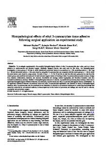
Figure 10. Modules connected in Simulink. 4.2. Experimental Results 4.2.1. Sinusoidal Sweeping-Frequency Vibration Tests In the sinusoidal sweeping-frequency vibration tests, the STI vibration controller generates a sinusoidal sweeping acceleration signal from 5 to 100 Hz, which amplitude is 0.5 m/s2, corresponding to the practical micro-vibration working conditions on the spacecraft. Dynamical responses without damping, with passive damping and under H∞ active control are tested, respectively, to analyze quantitatively the effect to the nature frequencies and amplitudes of the vibration response. The acceleration signals of the payload in three mutually perpendicular directions are captured by the STI controller. Three vibration experiments for the system without damping, with passive damper, and with H∞ active control are respectively tested. The acceleration amplitude-frequency curves measured from tests are shown in Figure 11, where the blue curve represents the acceleration amplitude of disturbance while the blue, purple and red curves represent the response acceleration amplitudes in three directions. The results show that the acceleration amplitude at first-order resonant frequency for the system with passive damping is reduced by 6.8 dB, 9.8 dB and 9.0 dB in three directions, respectively, in comparison with those for the system without damping, while the reductions rise to the level of 17.9 dB, 15.2 dB and 12.8 dB, respectively, for the case of active damping. The resonance frequency has a small drift for the system with passive damping or active control. This means the vibration isolation system does not significantly change the inherent characteristic of the structure. The results are shown in Tables 2–4.
Energies 2015, 8
8015
(a)
(b)
(c) Figure 11. The acceleration amplitude-frequency curves of the payload: (a) without damping; (b) with passive damping; (c) with H∞ active control. Table 2. Test results along x-axis. Damping Without damping Passive damping H∞ control
Resonance Frequency (Hz) 14.524 14.117 15.375
Vibration Amplitude (m/s2) 2.000 0.916 0.253
Magnification (dB) 12.041 5.259 −5.917
Energies 2015, 8
8016 Table 3. Test results along y-axis.
Damping Without damping Passive damping H∞ control
Resonance Frequency (Hz) 14.524 14.905 11.650
Vibration Amplitude (m/s2) 2.539 0.815 0.442
Magnification (dB) 14.114 4.244 −1.071
Table 4. Test results along z-axis. Damping Without damping Passive damping H∞ control
Resonance Frequency (Hz) 14.562 14.905 15.576
Vibration Amplitude (m/s2) 10.878 3.854 2.502
Magnification (dB) 26.752 17.739 13.986
4.2.2. Fixed-Frequency Vibration Tests In the fixed-frequency vibration tests, the acceleration amplitude of excitation is given as 0.5 m/s2 at the first-order resonance frequency, applied by the shaking table. The real-time control force obtained from the H∞ control law are captured and compared to monitor if the signals reach saturation. 2
F 2 (N)
F 1 (N)
2
0
-2
0
-2 0
1
2
3
0
-2
2
3
0
1
2
3
0
1
2
3
0
-2 0
1
2
3
2 F 6 (N)
2
F 5 (N)
1
2
F 4 (N)
F 3 (N)
2
0
0
-2
0
-2 0
1
2
Time (s)
3
Time (s)
Figure 12. Time-domain control force on each leg.
Energies 2015, 8
8017
Figure 12 shows the time-domain control force applied on each leg at 15 Hz which is around the resonance frequency. Unbalanced control force among legs is observed from Figure 12, which reveals the coupling vibration of the x axis, y axis and rotation for the reason of the asymmetry of the machining and assembling. With properly selections of the weighting function of W2 in Section 3.2, the peak value of the control force reach to maximum value at resonance frequency, which is driven by a current of 0.42 A according to the current-force constant of the actuators. The energy consumption is limited to the realizable range of the real equipment for a spacecraft without overloading. 5. Conclusions A VCM-based Stewart platform used for active vibration isolation of the payload carried on spacecraft has been studied in several aspects. The kinematics and dynamical equations of the Stewart platform with spherical joints at both the base and top of each leg have been established with the Newton-Euler Method in task space for the purpose of fully isolating the payload from the vibration source in multiple DOF. The equations are transformed into state space for the purpose of controller design. A robust controller according to the H∞ Control Theory is proposed for the corresponding linearized system with the constant parameter uncertainty, noise and sensor error. Finally, a Stewart platform with six VCM based extensible legs is constructed with spherical joints connections, and the vibration test on the payload supported by the Stewart platform has been taken. Sinusoidal sweeping-frequency and fixed-frequency vibration source is applied to the bottom of the structure and the active control force is determined by the dSpace real-time control system according to the output acceleration at the top of the legs. Measured data from the test have been used to verify the feasibility and effectiveness of the vibration isolation system by comparing the amplitude-frequency characteristics of the active control system with that of the passive control system and the system without control. The results of physical experiments indicate that the VCM-based Stewart platform with the proposed controllers is feasible in practical applications, which enhances the damping and stability of the structure effectively for vibration isolation. Acknowledgments The authors are grateful to the Foundation of Civil Astronautics and the Pre-research Foundation of General Armament Department of China for financial support in this study. Author Contributions Weichao Chi had the original idea for the study and drafted the manuscript. Dengqing Cao contributed to the guidance and revision work of the paper. Dongwei Wang established the dynamical equations and the control law. Jie Tang did a lot of work on machining and experiments. Yifan Nie and Wenhu Huang offered valuable suggestions to the work. Conflicts of Interest The authors declare no conflict of interest.
Energies 2015, 8
8018
Nomenclature t pi bi
position of platform
r li
position of center of mass of payload
position of upper end of ith leg position of lower end of ith leg vector of the ith leg
T R I θ α ω F Fa
transformation matrix rotation matrix moment of inertia rotation angle acceleration angular velocity force vector between the upper and the lower legs
Fw
external force on the top platform
Mw Mp
external torque on the top platform
K C
stiffness matrix of the legs damping matrix of the legs
active control force
the mass of the top platform
References 1.
2.
3. 4. 5. 6.
7.
Kurt, M.; Slavkin, I.; Eriten, M.; McFarland, D.M.; Gendelman, O.V.; Bergman, L.A.; Vakakis, A.F. Effect of 1:3 resonance on the steady-state dynamics of a forced strongly nonlinear oscillator with a linear light attachment. Arch. Appl. Mech. 2014, 84, 1189–1203. Kurt, M.; Eriten, M.; McFarland, D.M.; Bergman, L.A.; Vakakis, A.F. Frequency-energy plots of steady-state solutions for forced and damped systems, and vibration isolation by nonlinear mode localization. Commun. Nonlinear Sci. Numer. Simul. 2014, 19, 2905–2917. Fuller, C.C.; Elliott, S.; Nelson, P.A. Active Control of Vibration; Academic Press: Salt Lake City, UT, USA, 1996. Preumont, A.; François, A.; Bossens, F.; Abu-Hanieh, A. Force feedback versus acceleration feedback in active vibration isolation. J. Sound Vib. 2002, 257, 605–613. Chen, Y.-D.; Fuh, C.-C.; Tung, P.-C. Application of voice coil motors in active dynamic vibration absorbers. IEEE Trans. Magn. 2005, 41, 1149–1154. Fujii, Y.; Hashimoto, S. Evaluation of the dynamic properties of a Voice Coil Motor (VCM). In Proceedings of the 14th International Conference on Mechatronics and Machine Vision in Practice, 2007. M2VIP 2007, Xiamen, China, 4–6 December 2007; pp. 57–61. Park, K.; Choi, D.; Ozer, A.; Kim, S.; Lee, Y.; Joo, D. A voice coil actuator driven active vibration isolation system with the consideration of flexible modes. Rev. Sci. Instrum. 2008, 79, doi:10.1063/1.2930810.
Energies 2015, 8 8.
9. 10.
11. 12. 13. 14. 15. 16. 17.
18. 19.
20.
21. 22.
8019
Kim, Y.; Kim, S.; Park, K. Magnetic force driven six degree-of-freedom active vibration isolation system using a phase compensated velocity sensor. Rev. Sci. Instrum. 2009, 80, doi:10.1063/1.3117462. Kerber, F.; Hurlebaus, S.; Beadle, B.; Stöbener, U. Control concepts for an active vibration isolation system. Mech. Syst. Signal Process. 2007, 21, 3042–3059. Chi, W.; Cao, D.; Huang, W. Design of active whole-spacecraft vibration isolation based on voice-coil motor. In Proceedings of the SPIE Smart Structures and Materials + Nondestructive Evaluation and Health Monitoring, San Diego, CA, USA, 9–13 March 2014; doi:10.1117/12.2044920. Stewart, D. A platform with six degrees of freedom. Proc. Inst. Mech. Eng. 1965, 180, 371–386. Fichter, E.F. A Stewart platform-based manipulator: General theory and practical construction. Int. J. Robot. Res. 1986, 5, 157–182. Bonev, I.A.; Ryu, J. A new method for solving the direct kinematics of general 6-6 Stewart Platforms using three linear extra sensors. Mech. Mach. Theory 2000, 35, 423–436. Lebret, G.; Liu, K.; Lewis, F.L. Dynamic analysis and control of a Stewart platform manipulator. J. Robot. Syst. 1993, 10, 629–655. Dasgupta, B.; Mruthyunjaya, T. A Newton-Euler formulation for the inverse dynamics of the Stewart platform manipulator. Mech. Mach. Theory 1998, 33, 1135–1152. Dasgupta, B.; Mruthyunjaya, T. Closed-form dynamic equations of the general Stewart platform through the Newton-Euler approach. Mech. Mach. Theory 1998, 33, 993–1012. McInroy, J.E. Dynamic modeling of flexure jointed hexapods for control purposes. In Proceedings of the 1999 IEEE International Conference on Control Applications, Kohala Coast, HI, USA, 22–27 August 1999; pp. 508–513. Mukherjee, P.; Dasgupta, B.; Mallik, A. Dynamic stability index and vibration analysis of a flexible Stewart platform. J. Sound Vib. 2007, 307, 495–512. Preumont, A.; Horodinca, M.; Romanescu, I.; de Marneffe, B.; Avraam, M.; Deraemaeker, A.; Bossens, F.; Hanieh, A.A. A six-axis single-stage active vibration isolator based on Stewart platform. J. Sound Vib. 2007, 300, 644–661. Xu, P.; Wang, D.H. Vibration damping modeling of Stewart platform through Newton-Euler approach. In Proceedings of the Smart Structures and Materials, San Diego, CA, USA, 17 May 2005; doi:10.1117/12.602670. Chi, W.C.; Cao, D.Q.; Huang, W.H. An Observer-Based Active Vibration Isolation System Using the Voice-Coil Actuator. Adv. Mater. Res. 2014, 846, 161–166. Chow, T.L. Introduction to Electromagnetic Theory: A Modern Perspective; Jones & Bartlett Learning: Burlington, MA, USA, 2006.
© 2015 by the authors; licensee MDPI, Basel, Switzerland. This article is an open access article distributed under the terms and conditions of the Creative Commons Attribution license (http://creativecommons.org/licenses/by/4.0/).