blacksmith's swages. The automated repair welding process restores the tool with ... is controlled by both the computer system and robot control. 1 Introduction.
Design and Implementation of a System for Autonomous Repair Welding Matthias Hackel1 , Stefan Kremer-Wasmuht1 , G¨unther Starke1 1 APS
- European Centre of Mechatronics, Aachen, Germany {hackel,kremer,starke}@aps-mechatronik.de
Abstract — This paper presents the design and implementation of a system applicable for autonomous repair welding on huge forming tools, often realized as blacksmith’s swages. The automated repair welding process restores the tool with its desired shape independent to the tools actual state of abrasion. The core of the system is provided by a computer connected to sensors and an eight axis welding robot. The automated process, consisting of several measuring and welding cycles, is controlled by both the computer system and robot control.
1
Introduction
Today, construction changes and repairs on forming tools are still realized manually. Since the manual work results are not reproducible, they often involve a cost and time consumptive post processing. From today’s view the repair welding often has a ”Trial and Error” character. By use of 3d - scanning sensor, temperature sensor, advanced software algorithms and a weld tool equipped robot, an adaptive control system for autonomous repair welding, which requires minimal user intervention, can be developed. Such a system has been realized at APS, Aachen. The working system automatically detects lack of material in the tool due to abrasion in its use, plans and carries out the necessary welding steps to restore the tools original shape. The next chapters describe the essential components of the system and its components. Section 2 shows principles and design of the scanning and infrared sensors. Chapter 3 deals with the structure of the complete system and its interfaces, the software is described in chapter 4. In chapter 5 the procedure of a repair cycle is shown. Conclusions and future work are to appear in Sect. 6.
2
Sensors
Sensors make up the interface to the outer world, they allow to react on altering environmental conditions and actual process parameters. Two most important sensors of the system are described in the following: A thermal sensor (pyrometer) is used to observe
HACKEL, KREMER-WASMUHT, STARKE
and limit the heating-up of the workpiece during the welding process. The 2D - line scanning sensor allows to record the 3D - geometry of the workpiece by attaching it to an industrial robot. 2.1
Thermal Infrared Sensor
The applied thermal sensor is used to measure the temperature of solid bodies due to their thermal radiation in the infrared range[1]. This allows a contactless temperature measuring of the workpiece. The cross section of the according observation area can be adjusted with integrated optics in the range from two up to 20 square millimeters, depending on the distance to the object. The purchased sensor is attached on a fixed place within the robot work area and observes the temperature of the workpiece during the weld process. The measuring ranges cover temperatures from 200 to 1200 degrees (celsius) at a distance from 350 to 2400 millimeters. To ensure reliable temperature data, neither radiation from the welding process nor the robot itself should cross the observation path. The sensor is connected via serial RS 232 interface to the controlling PC. If the temperature in the observed region of the workpiece exceeds a critical value (typical 650 degrees), the welding will stop, to be continued after cooling down below the lower control value (typical 350 degrees). Otherwise the weld seam layers would just stay to long in a melted state and not solidify in their assumed shape[2]. 2.2
Geometry Scanning Sensor
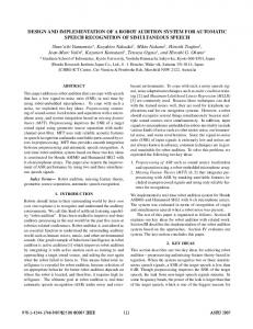
The sensor for recording the shape of the workpiece is realized as 2D - line scanning sensor, utilizing the triangulation principle. Therefore a laser beam reflected by the objects surface is detected with a camera. The position of the signal on the sensitive camera chip depends on - the fixed distance d and orientation of laser module and camera, - the focal lenght f and - the actual distance object - sensor.
Figure 1: Triangulation sensor principle (left) and the realized sensor mounted on the robot arm (right)
AUTONOMOUS REPAIR WELDING
A 2d - line scanning sensor was developed at APS to satisfy the specifications regarding measuring range and robustness. The laser module is equipped with a cylindric lens and therefore produces a thin laser line (in visible red - 638 nm wave length), the CCD chip features 480 x 640 pixels. As the sensor is not using movable parts, it will stand normal accelerations turning up at the tool center point (TCP) of industrial robots [3]. The realized sensor as well as the triangulation principle is shown in figure 1. The CCD - camera is connected via framegrabber to an image processing PC. With the developed software several standard imaging processing filters can be applied to the image - the aim is to extract the localization of the laser line from the real world image. As the camera is in a fixed position to the laser module and operates at a fixed focal length, each pixel illuminated by laser represents a 2D - position in the coordinate system of the sensor. After some basic filtering operations and gap filling algorithms, one single line with 2D information is calculated from one picture. A screenshot of the image processing software can be observed in 2.
Figure 2: Screenshot of the image processing software. It shows a grabbed camera image with laser line on the right, the histogram on the left illustrates the intensity distribution in the image. The camera hands out an 8-bit (grey) bitmap, although it appears to be colored in this figure The line scanning sensor is physically attached to the robot, during measurement it is moved on a linear axis with constant speed [4]. The main PC receives the 2D data in fixed time steps to build up a 3D - model of the scanned region. To acquire the image and send the 2D - data information at predefined time intervals, the image processing PC communicates via TCP/IP with the other PC. To send and receive data, the software includes both client and server. The communication part of the whole system is described in more detail in chapter 3.1.
3
Systems Structure
The systems structure, consisting of main process PC, sensors and an industrial eight axis robot with tool changer and welding equipment is drafted in figure 3. For measurement of the objects shape with the laser scanning sensor, the robot is forced by the PC to pick
HACKEL, KREMER-WASMUHT, STARKE
up the sensor and place it in the desired position. To ensure time critical communications between PC and robot, four digital I/O channels are used as hardware handshake lines.
Figure 3: Structure and interfaces of the system 3.1
The Measurement Process - Interfacing and Timing
The whole process is managed by the main PC. First the structure of the damaged tool has to been recorded - if the damage occurs only in a pre-known region and the tool is located at the desired position inside the robot cell, the process can run without any further user intervention. The robot places the sensor above the region of interest, then waits for a PC signal to start moving the sensor on a linear line with constant speed. The PC sends the start signal to the Robot and image processing PC (ipPC) simultaneous, whereby the start signal for the ipPC contains the size of time gap between two line scans in milliseconds. It is calculated by t = T GES/Z Columns
(1)
whereby TGES is the whole time needed for driving that linear line; ZColumns is the number of scan lines referring to the desired resolution. Since the measuring process starts at time zero, t can be calculated as simple. The time needed for image processing gives a constant delay - the 3D model transferred in coordination system of the robot cell has to be moved in contrary direction to the robot movement according to this delay. Sending the start signal via TCP/IP to the ipPC, the main PC acts as TCP - client, receiving the data he acts as server in the measuring process. During the weld process the PC hands over the control to the robot, and can act as simulation tool. It only interferes when the connected pyrometer detects a temperature exceeding the limit.
AUTONOMOUS REPAIR WELDING
The main PC transfers generated programs for measuring and welding to the robot control via serial communication (RS 232). As well some simple robot control commands can be disposed using this DNC - interface.
4
Control and Process Software
The operating system on the PC is Windows NT 4.0. A freeware device driver1 allows one to access all ports (e.g. parallel port). The developed software has to perform several tasks, in specific the – management and timing of the measurement to obtain geometry data, – build up a 3D - model and place it in the ”real world” robot cell, – detect defects in the model and find strategies for filling them by build-up welding, – generate robot weld programs, – transferring and starting / intercepting programs (temperature watch). Since the management and timing of the measurement process is described in chapter 3.1, this chapter will deal with defect detection and virtual filling of those defects with weld seams. To allow the defect detection, the system has to know the original shape of the workpiece. As a 3D CAD model, this shape is available in stereolithography (STL) format used for rapid prototyping. This format describes solids with triangles of inner and outer face. To detect existing defects, the ”ideal” CAD and the recorded Data have to be compared. For algorithm developing and user monitoring the 3D data can be observed using OpenGL - although a graphical display is not necessary once the process is established.
Figure 4: The left screen shows the measured data and the CAD wireframe, in the background the robot worktable with coordinate system pointing in z- direction. The right screen shows weld seams calculated for only one plane of the workpiece Figure 4 shows two screen shots - on the left a big part of the workpiece (in this case a chain link of a huge digger) was scanned and lies below the wireframe CAD - data of that object. On the right screen, models of weld seams are filing the space between measured 1
Paula Tomlinson’s program LOADDRV, to be found for download in www.
HACKEL, KREMER-WASMUHT, STARKE
(used-up) surface and the original CAD surface. The process of metal active gas welding (MAG) allows to build up material only on other weld seams or base metal material, therefore no drip mould could be constructed with this process. In repairing tools with known defects this means no disadvantage, diverse in the case of rapid prototyping applications. Since material can only be added in that way, for defect detection a virtual scan ray from the lower measured geometry scans in positive z- direction for intersection with surfaces from the original data. Hereon a virtual 3d solid is generated, describing the space in between. Another virtual scan ray (in this case from the lower left corner, the y -direction) than hits that solid in equidistant intervals representing the weld distances in the ”real world” to generate the weld grubs. The robot actually needs BASIC - style programs to function, those are generated from the virtual weld seam data and compiled with a robot specific compiler. The binary program then is send to the robot control via RS 232. The software can autonomous force the robot to execute that programm as well to change the tools via the same serial communication. Not needed for this application, the user can as well define single ore successive weld seams with the same software and use it as off-line tool for fast and easy robot teaching.
5
Automated Repair Welding - The Process
All systems components and their specific functionalities have been described so far, this chapter describes one process flow of a automated repair welding procedure. Figure 5 shows a flowchart explaining single steps and involved components.
Figure 5: Automated repair welding - flowchart Once the user placed the workpiece in the robot cell and started the process, it runs in autonomous mode. Up to now, the user in before has to ensure that the virtual CAD model in the PC programm is congruent to its position in the real world. If always the same
AUTONOMOUS REPAIR WELDING
workpiece with different states of abrasion has to be repaired, the system could place the virtual model by measuring defined points (three points at least) on the workpiece in areas of no abrasion. To illustrate the ”real world” workpiece from figure 4 with its dimensions, figure 6 shows the robot work cell, the robot with line scan sensor attached.
Figure 6: The robot cell with digger chain link, this one is new and unused - to calibrate and test the systems accuracy, the obtained 3D data should fit with the 3D CAD data
6
Conclusions, Future Work and Outlook
In this paper a successful implementation of a system for automated repair welding was presented. It was shown, that intelligent solutions in embedded systems can as well have an impact on ”conservative” heavy industry machine processes. Some details of the system have to be improved in future - especially slow communication paths have to be replaced by faster ones. Since NT 4.0 is no longer supported and provides no real time facilities, the desired operating system will be Linux with real time kernel. Furthermore, we would like to replace the image processing PC by a powerful microcontroller system. The presented system could as well be used for rapid prototyping plastic deformation tools [5]. A simulation tool for the weld process would be useful - the process could be planned more precisely with better matching the desired shape. In situ process sensors, most favored in this case the arc sensor, could enhance controlling the weld process by recognizing actual geometry of layers and seams [6, 7]. In lots of cases, a brilliant realization of a sensor could be given by the actuator himself, if one can access parameters suitable for controlling the according value. This helps reducing size and effort for intelligent control systems, putting them into a simple and robust state with no additional sensitive sensors. Since industrial robots in our time obtain a wide range of fast interfaces, manifold complex production processes will be automated in future. Fast data streams and advanced
HACKEL, KREMER-WASMUHT, STARKE
sensors allocating minimal data processing time will lead to more flexible automation systems [8]. As fast ethernet will uprise in automation processes, the set-up-time for complex systems will be reduced as well as the maintenance effort. Automation then is to become more effective even for a small number of items and custom-made products. The end user could then affect the design of his specific product, preferred via the www. As well automation and intelligent control systems wont stay inside factories and production halls, they will swap out and effect our daily life.
References [1] Gochermann, Nelke, Lutz: Noncontact Infrared Sensor Delivers Point-Accurate Measurement; Photonics, April/May 1999 [2] Starke, G.; Bach, C.: Condition Monitoring with Controlled Repair Capabilities for Process Automation in Repair Welding Services; IECON 98, Aachen, 1998 [3] Drews, P.; Pieper St.; Willms, K.: Optical Sensor System for 3D - Path Tracking in Laser Weld Applications(GER); Springer, Engineering Research, p.66, 2000 [4] Levoy, M., Ginsberg, J., Shade, J. a.o.: The digital Michelangelo project: 3D scanning of large statues; ACM Press/Addison-Wesley Publishing Co. New York, USA, 2000 [5] Paul, B.K.: Rapid Prototyping and Freeform Fabrication; Materials and Processes in Manufacturing, 9th Ed., DeGarmo, Black and Kohser (Eds.), Prentice-Hall, 1999 [6] Kovacevic, R., Zhang, Y. M. :Real-time image processing for monitoring of free weld pool surface; ASME Journal of Manufacturing Science and Engineering, 1997 [7] Fourligkas, N., Doumanidis, C.: Hybrid modeling for control of rapid prototyping by plasma arc welding material deposition; Source Technology Conference, Houston, TX, USA, 1999 [8] Stecke, K.E.: Design, Analysis, and Operation of Manufacturing and Assembly Systems; International Journal of Flexible Manufacturing Systems, Kluwer Academic Publishers, Volume 15 (4 issues), 2003
About the Authors Matthias Hackel received his Master’s degree in physics in 1997 from RWTH Aachen, Germany. His current research within the fields of robotics and automation focuses on off-line programming, online process simulation, sensor data processing and sensor fusion. Stefan Kremer-Wasmuht received his Master’s degree in metallurgy in 1989 from RWTH Aachen, Germany. In 1995 he became European Welding Engineer. At APS his activities are focussed on process control and automation for miscellaneous welding applications. Dr. G¨unther Starke received his PhD in engineering in 1983 from RWTH Aachen, Germany. As head of APS research department his research and teaching activities are focused on mechatronics - especially robotics, automation and intelligent process planning.