. J. M. Ramırez-Cortés is a titular researcher at the Electronics Depar
Design and Implementation of the Discrete Wavelet Transform on an FPGA Platform to Process Data Sets of up to Three Dimensions E. A. Rivera-Juarico, Student Member, IEEE, J. M. Ram´ırez-Cort´es, Senior Member, IEEE, V. Alarcon-Aquino and J. Escamilla-Ambrosio, Member, IEEE
Abstract—The aim of this work is the design and implementation of a DWT architecture FPGA-based platform for up to three dimensional signal processing. First, filter banks are designed using a distributed arithmetic technique. Then, we design controllers, interfaces and protocols that handle, transmit and sequence all the data during the computing process. Data is sent via USB to the FPGA and the user interface is programmed in MATLAB. A graphical user interface manages the system operation and displays the results on a PC. Designed filters are compared with a fully parallel architecture in relation to the number of gates used, speed, and algorithm performance. Keywords—Daubechies, Distributed Arithmetic, Filter Design.
ψ up to order n exist and are bounded. A set of orthogonal functions with compact support, widely used now in the wavelet field, and a method to obtain the corresponding filter coefficients was proposed by Ingrid Daubechies [3]. Several interesting properties are listed below. A. Multiresolution A multi-resolution or multi-scale scheme consists of a sequence of successive approximation spaces Vj with the following conditions:
I. I NTRODUCTION Wavelet signal processing is a technique that can be used to analyze the temporal and spectral properties of non-stationary signals. A prototype function called Mother Wavelet (ψ) is stretched and shifted to obtain an orthogonal function set that is used to analyze in a multiresolution approach the time-scale energy distribution of signals. Mother Wavelets can be designed to achieve different requirements. Essentially, mother wavelets are oscillating waves with finite energy and short duration (conditions 1 and 2) that are well localized in the time and frequency spaces [1]. The designers can use the well documented mother wavelets functions found in literature [2] or they can propose their own wavelets to use special characteristics to reach their purposes. So, wavelet theory can view as a flexible signal processing framework rather than a simple transformation. Z ψ dt = 0 (1) Z
+∞
cψ = 2π −∞
|Ψ(ω)|2 dω < ∞ |ω|
(2)
One type of mother wavelet can be distinguish by a property named compact support such that all derivatives of function This work was supported by CONACYT grant No. 290541 E. A. Rivera-Juarico is a MSc by National Institute of Astrophysics, Optics and Electronics, St. Ma. Tonantzintla, PUE, Mex., e-mail:
[email protected] J. M. Ram´ırez-Cort´es is a titular researcher at the Electronics Department, National Institute of Astrophysics, Optics, and Electronics, St. Ma. Tonantzintla, PUE, Mex., e-mail:
[email protected]. V. Alarcon-Aquino is titular professor at the Electronics Department, Universidad de las Americas, Puebla, Mex., e-mail:
[email protected] J. Escamilla-Ambrosio is a titular professor at the Electronics Department, Universidad Politcnica de Guanajuato, Mex., e-mail:
[email protected]
978-1-61284-1325-5/12/$26.00 ©2012 IEEE
...V2 ⊂ V1 ⊂ V0 ⊂ V−1 ⊂ V−2 ⊂ ...
(3)
∪j∈Z Vj = L2 (R)
(4)
∩j∈Z Vj = {0}
(5)
The condition 3 says that V0 is a central space which includes all subspaces Vj with j ∈ +Z and belongs in turn to a series of spaces Vj with j ∈ −Z. In addition the complex conjugate of the union of all spaces should be a function in L2 (R) as indicated by the condition 4. These spaces should be independent, and thus their intersection must be zero (condition 5). In addition, the multi-resolution appearance is a consequence of the following requirements: f ∈ Vj ⇔ f (2j · ) ∈ V0
(6)
f ∈ V0 ⇒ f (· −n) ∈ V0 , ∀n ∈ Z
(7)
That is, all spaces are scaled versions of the central space V0 (condition 6) and V0 is invariant under integer translations (condition 7). This implies that if f ∈ Vj , then f (· −2j n) ∈ Vj , for all n ∈ Z. Finally it requires that there be a function φ ∈ V0 such that φ0,n ; n ∈ Z (8) is a normalized orthogonal basis in V0 , where ∀{j, n} ∈ Z, φj,n (s) = 2−j/2 φ(2−j s − n)
(9)
This implies that {φj,n ; n ∈ Z} is a normalized orthogonal basis in Vj for all j ∈ Z. The function φ is called scaling
333
function multi-resolution analysis and equation 9 is known as dilation equation. Multi-resolution analysis can be described through a pyramidal structure that decomposes a signal into the approximations and details coefficients, creating a level of decomposition. It is required to apply the same scaling function φ and mother wavelet ψ in each level on scaled versions of the input signal obtained through the previous levels. The multi-resolution leads naturally to a hierarchical and fast computation of wavelet coefficients at different scales of a given function or sequence. B. Filters Banks for Wavelets Suppose, has been obtained the inner product of f with φ0,k , i.e. the scale j = 0. Then the calculation of hf, ψj,k i for j ≥ 1 is as follows: starting with hf, φ0,n i, estimate hf, ψ1,n i by, hf, ψj,k i =
X
gn−2k hf, φj−1,k i
(10)
n
Which can be obtained by the convolution of hf, φj−1,k i with g−n , for n ∈ Z and retaining only pairs of output samples (decimation by a factor of 2). Then hf, φ1,n i is calculated using a similar process of convolution and decimation given by, hf, φj,k i =
X
hn−2k hf, φj−1,k i
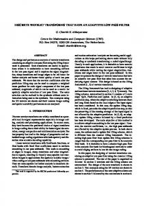
Fig. 1: Wavelet decomposition for three dimensional functions. low pass filter and high pass for each dimension respectively. The whole procedure is shown in fig. 1 where partial results are displayed in each dimension filtering: (a) original volume, (b) filtering output in x, (c) filtered output in y, and (d) filtering output in z which represents the final result of the DWT descomposition three dimensional process at one level. Fig. 2 shows the resulting filtering scheme using filter banks; (a) for x, (b) for y and (c) for z directions.
(11)
n
This can be found for all the family functions ψ and φ , which is useful for multiple levels of wavelet coefficients. The entire procedure can be viewed as the computation of approximations of f , together with the difference in information between two successive levels of approximation. The function ψ can be viewed as a high pass filter where we get the wavelet coefficients and the function φ as a low pass filter which gives us the coefficients of approximation to calculate the next level of decomposition by feeding this output to another pair of filters.This pair of filters are known as analysis filter banks. Then the next level decomposition gives us a representation of f with a version of ψ and φ scaled by a factor of 2j with j the level of decomposition. Moreover, the multiresolution analysis occurs when there are different levels or scaled versions of the input signal. In order to obtain j decomposition levels, j analysis filter banks are connected in such a way that the approximation coefficients of level j − 1 enters the level j with j > 1 , and j = 0 corresponds to the initial level of the original signal f .
2
LPF
2
LPF
2
HPF
f(n)
LPF
HPF
2 2
2
LPF
2
HPF
2
LPF
2
LPF
2
HPF
(a)
2
HPF
(b)
2
HPF
2
LPF HPF
(c)
2
LLL
LLH LHL
LHH
HLL HLH HHL HHH
Fig. 2: DWT filtering scheme for functions in three dimensions. In a general point of view, n-dimensional functions can be processed by a similar procedure of filtering in every dimension.
C. DWT processing on Three Dimensional data sets Processing functions in three dimensions can be considered as a combination of one-dimensional DWT applied to each of the dimensions of the function to be processed. So, what is considered a data volume of N1 N2 N3 , is divided into eight sub-volumes with dimensions N21 N22 N23 each. The following nomenclature is used for sub-volumes: LLL, LLH, LHL, LHH, HLL, HLH, HHL, HHH. Where L and H denote the outputs of 978-1-61284-1325-5/12/$26.00 ©2012 IEEE
D. Distributed Arithmetic Equation 12 (linear convolution) can be modified with distributed arithmetic (DA) to process signed numbers in 2’s complement [4].
334
y[n] = f [n] ∗ x[n] =
L−1 X k=0
f [k]x[n − k]
(12)
In 2’s complement, the most significant bit is used to distinguish between positive and negative numbers. If |x[n]| < 1, then it can be represented by, x[i] = −x0 [i] +
B−1 X
−b
xb [i]2
(13)
b=1
With b = 0 representing the most significant bit (and sign bit) and b = B − 1 least significant bit. The distribution of the architecture for the linear convolution is given by, y[i] =
N −1 X
c[n]x[i − n]
II. M ATERIALS AND M ETHODS A. Target Technology and Tools Field programmable gate array (FPGA) Spartan3E XC3S1200e-4fg320 of Xilinx Inc. over Nexys2 development board of Digilent Inc. was selected as primary target technology. Brief overview of this device is shown in table II. TABLE II: OVERVIEW XC3S1200e-4fg320.
(14)
Gates Equivalent Logic Cells Total CLBs Total Slices Distributed RAM bits Block RAM bits Dedicated Multipliers DCMs Inputs/Outputs Differential Inputs/Outputs pairs
n=0
y[i] =
N −1 X
" c[n] −x0 [i − n] +
n=0
y[i] = −
y[i] = −
N −1 X
N −1 X
c[n]x0 [i − n] +
c[n]
B−1 X
n=0
n=0
b=1
N −1 X
N −1 X
B−1 X
c[n]x0 [i − n] +
N −1 X
N −1 X
c[n]
n=0
c[n]x0 [i − n] +
n=0
y[i] = −
xb [i − n]2−b
(15)
b=1
n=0
y[i] = −
#
B−1 X
xb [i − n]2−b (16)
−b
xb [i − n]2
(17)
b=1
N −1 B−1 X X
c[n]xb [i − n]2−b (18)
n=0 b=1
c[n]x0 [i − n] +
B−1 X
n=0
b=1
2−b
N −1 X
c[n]xb [i − n] (19) {z
hc[n],xb [i−n]i
}
TABLE I: LU T CONTENTS IN GENERAL DA SCHEME
x1[i]
xB-1[i]
x0[i-1]
x1[i-1]
xB-1[i-1]
xb [i − 1] 0 0 0 0 .. . 1
LUT x0[i-N+1]
1200K 19512 2168 8672 136k 504K 28 8 304 124
Design tools used were MATLAB R2010b (Wavelet Toolbox 4.6, Filter Design Toolbox 4.7.1 and Filter Design HDL Coder 2.7) from The MathWorks Inc. for wavelet filter banks design, DA HDL code generation and user interface for running and debugging purposes. Other tools used were ISE WebPack 12.4 from Xilinx Inc. for implementation of designed filters, ADEPT 2.6.1 System and Adept 2.0.1 SDK from Digilent Inc. for programming and data transmission from the register bus implemented on the FPGA system.
y[i]
+/-
x1[i-N+1] xB-1[i-N+1]
2-1
{
+ 0≤b


![[PDF]EPUB The Design and Implementation of the ... - Google Sites](https://m.moam.info/img/260x300/pdfepub-the-design-and-implementation-of-the-googl_64786f8f097c4796708ccea2.jpg)

