Design and optimization of optical modulators based on graphene‐on‐silicon nitride microring resonators
Zeru Wu, Yujie Chen*, Tianyou Zhang, Zengkai Shao, Yuanhui Wen, Pengfei Xu, Yanfeng Zhang, and Siyuan Yu State Key Laboratory of Optoelectronic Materials and Technologies, School of Electronics and Information Technology, Sun Yat‐sen University, Guangzhou 510275, China *E‐mail:
[email protected] (Yujie Chen)
Abstract In order to overcome the challenge of obtaining high modulation depth due to weak graphene‐light interaction, a graphene‐on‐silicon nitride (SiNx) microring resonator based on graphene’s gate‐tunable optical conductivity is proposed and studied. Geometrical parameters of graphene‐on‐SiNx waveguide are systematically analyzed and optimized, yielding a loss tunability of 0.04 dB/μm and an effective index variation of 0.0022. We explicitly study the interaction between graphene and a 40‐μm‐radius microring resonator, where electro‐absorptive and electro‐refractive modulation are both taken into account. By choosing appropriate graphene coverage and coupling coefficient, a high modulation depth of over 40 dB with large fabrication tolerance is obtained.
1. Introduction Graphene photonics has received a lot of interest due to its outstanding electrical and optical properties of ultrahigh carrier mobility [1], wide operational bandwidth [2], and electrically tunable conductivity [3]. graphene‐based photonics devices such as high‐speed photodetectors [4,5], electro‐optical modulators [6,7], optical polarizer [8] have been demonstrated. Integrating graphene with passive optical waveguide structures is an effective way to enhance the interaction between light and the graphene sheet [9]. However, the overlap between the evanescent field and graphene is not strong enough to obtain a significant change of optical absorption [10]. To extend the graphene‐light interaction, exploiting resonant‐enhanced cavity structure is a promising approach and several silicon cavity integrated graphene‐based photonics devices with enhanced performance have been reported [11–15]. Compared to silicon waveguides, silicon nitride (SiNx) waveguides have much lower losses, broader transparency windows, smaller thermal‐optic effects, and larger fabrication tolerance [16]. Therefore, graphene‐based device integrated on SiNx platform may afford better performance [17–20]. 1
In tthis work, a a comprehe ensive studdy on the design d optim mization off graphene‐‐SiNx microring modulator is presented. Thhis involves firstly a detailed analyysis of optim mum wavveguide parameters for f enhanc ed grapheme‐light in nteraction. Based on the optiimized wavveguide stru ucture, sevveral design n principless for grapheene‐based SiNx microring mod dulator devices are prooposed. The ese design rrules are th en applied to a 40‐μ μm‐radius microring m modulator m tto produced optimized d device deesigns that can provvide a high modulation n depth of oover 40 dB. 2. Simulation o of graphene e‐SiNx waveeguides 2.1 Modelling methodolo ogy for simu ulation Ourr simulation ns are perfo ormed usin g the finite e differentia al eigonmodde solver (FDE) and d graphene is charactterized usinng a surfacce conducttivity modeel. The surrface e derived fro om the Kubbo formula [[21], conductivity off a single layyer of graphhene can be ( , , , T )
f d ( ) f d ( ) ie 2 ( i 2) f d ( ) f d ( ) d )d 0 ( 2 0 ( i 2 ) 2 4( ) 22 (1)
wheere is th he radian frrequency off incident ligght, the e reduced P lank’s consttant, tthe chemical potential that can b be electro‐sttatically con ntrolled, the scatte ering
ratee, T the tem mperature, aand e is thee charge off an electron. f d ( ) (e k T 1) 1 iss the B
Ferm mi‐Dirac distribution, in which kB is the Boltzmann’s constant.. The first and seco ond integraal term represent intraaband and interband conductivitty, respectively. Herre 0 e2 4 60.85 μS is the m minimum conductivity c y in the opptical‐freque ency regiime.
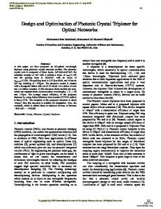
Fig. 1. Electriccal and opttical properrties including (a) con nductivity, ((b) permitttivity dex, and (d ) absorption coefficien nt of single layer graph hene constant, (c) reefractive ind as aa function of chemical p potential foor 1.55 μm , 0.08 eV and T 3000 K . 2
Thee following ccalculationss are based on the incident light w with 1.555 μm, 0.088 eV, and d T 300 K. Optical an nd electricaal propertie es including g conductiviity, permitttivity constant, refraactive index, and abssorption co oefficient as a functioon of chem mical poteential of graaphene are shown in FFig. 1. The optical and e electrical prroperties can be dram matically ch hanged via cchemical pootential tuning, which ccan be easi ly controlled by an applied vo oltage. Notte that whhen chemiccal potentia al increasees, the sign n of imaginary partt of permitttivity constaant can shifft from positive to neggative, impllying m dielectric‐‐like to metaallic‐like [22 2]. thatt graphene’s propertiess can be moodified from 2.2 Analysis, design, and o optimizatio on of graphe ene‐SiNx wa aveguides Effeect of wavveguide dim mensions and polariization of guided m modes on light prop pagation in a SiNx waveguide is innvestigated firstly. The refractive inndices of sillicon nitride and a 3‐μm‐thickk silicon diooxide (SiO2) ) substrate layer are 1.95 and 1.46, 1 resp pectively [16]. The elecctric field ddistribution of a quasi‐T TE guided m mode is plo otted in FFig. 2(a). To o improve electroabso e rption mod dulation efficiency, thee optical po ower confined at thee interface between thhe graphene e sheet and d the wavegguide should be 3]. We pe erform an exhaustive e paramete er sweep oof geomettrical maxximized [23 paraameters of an air‐clad d SiNx waveeguide. Afte er several algebraic a stteps, the siingle mod de condition and corre esponding ooptical pow wer confinem ment (definned as the rratio of p power in th he vicinity of o the top ssurface to the t total po ower in thee waveguide) is illusstratively sh hown in Figss. 2(b) and 2(c). Powerr confineme ent of the eevanescent field in aa quasi‐TE mode wavveguide is much largger than th hat in a qquasi‐TM mode m wavveguide. For a single T TE mode waaveguide with a cross‐section of 11.09 μm × 0.33 μm,, power con nfinement rreaches to 33.6% while tthe maximu um power cconfinement for a single TM mode waveguide is 0.800%, with a cross‐sectio on of 0.61 μm × 0.54 μm. Thu us, to imp prove electtroabsorptioon modulaation efficiency, a qquasi‐TE mode m ptical wavveguide witth a larger overlap beetween graphene layer and proppagating op mod de is preferaable.
Fig. 2 (a) Cross‐‐section of the SiNx waaveguide with an overla ay of electriic field intensity, (b) single mode condition n of the SiN Nx waveguid de, and (c) p power conffinement off the evanescent fielld in the viccinity of wavveguide surrface versus geometricaal paramete ers. 3
Afteer optimizattion, a TE m mode wavegguide with aa cross‐secttion of 1.099 μm × 0.33 3 μm is sselected for further simulation. s Effective index and propagatioon loss of the wavveguide as aa function o of chemical potential o of graphene e is shown iin Fig. 3(a). It is veryy importantt to be awaare that booth effective e index and d loss have e steep changes arou und 0.4 eV ~ 0.6 eV. A A loss tunabbility of about 0.0 o 04 dB/μm aand an effecctive indeex change Δneff of 0.0022 can b e achieved,, which is m much more significant tthan thatt of a TM mode wavveguide. Onn the othe er hand, with sufficieent variation of effeective indexx but much h lower los s, a TM mode m waveg guide is moore suitable e for construction of o an electtro‐refractivve phase modulator m [24–26] [ .Noote that th hese design principles for graphene‐SiNx w waveguidess are quite d different froom graphen ne‐Si wavveguides, ass quasi‐TM modes exhhibit stronge er interactio on over quaasi‐TE mode es in Si‐b based structtures [27]. This is du e to the re elative low refractive index conttrast betw ween SiNx aand SiO2, w which resultss in a large substrate leakage losss [28]. In fact, a TE m mode waveeguide is more compattible with tthe on‐chip optical inteegrated circcuits because most llaser diodess are operatting with TEE polarizatio on [10]. Thee bending lo oss of an un ndoped gra phene‐SiNx waveguide e as a funct ion of radiu us of curvvature is also obtained d [29], as sshown in Fig. 3(b). When the beending radiu us is largger than 35 μm, a limitting value i n the orderr of 0.06 dB B/μm is obttained, whicch is exacctly the valu ue of the lo oss of the sttraight grap phene‐SiNx w waveguide w we have so olved abo ove. Thus, we conclude that thhe bending loss of th he microrinng structurre is neggligible for raadius greate er than 35 μ μm.
Fig. 3. (a) Effecctive index and propaggation loss of the grap phene‐SiNx w waveguide as a funcction of cheemical potential of gra phene. (b) Bending losss versus beending radiu us of the waveguide. 3. O Optical mod dulators bassed on grap phene‐on‐SiiNx microrin ng resonatoors 3.1 Theoretical analysis fo or microringg resonatorr To achieve a better performance, it’s imporrtant to in nvestigate tthe interacction ween grap phene and microring resonatorss. Here we e study th e influence e of betw grap phene induced electro o‐refractive phase mod dulation effect and eleectro‐absorp ptive 4
amp plitude mo odulation effect e [30], which bo oth play an importannt role in the mod dulator. Con nsidering an n all‐pass tyype microrin ng resonato or structuree with graph hene coveering length of L, as schematical s lly shown in Fig. 4. κ is the field cross coup pling 2 2 coefficient, r is the transm mission coeffficient of th he coupling region andd r 1 in a losssless coupleer.
Fig.44 (a) Schem matic illustraation of the proposed ggraphene‐o on‐SiNx micrroring reson nator. (b) D Dependenccy of κ on co oupling gap of the micrroring reson nator.
upling coeffficient of a microring rresonator ccan be derivved based oon the coupled Cou mod de theory (C CMT) [31]. For a pair oof waveguid des with a w width of 2a and a heigh ht of 2d, the mode ccoupling coe efficient is ddescribed b by: 2
K=
2
0 ( n1 n0 ) 2
d
*
E1x E1x dxd dy a d * E1x H 1 y dxdy
a
(1)
n1 aand n0 repreesent the refractive inndices of waveguide and substratte, respectively. Thu us the cou upling coeffficient for a microring resonattor can bee obtained d by e coupling rregion, inteegrating oveer the entire
= sin(R 2 K exp( (g 2 R sinn 2 )) cos2 d )
2
2
(2)
2 2 2 wheere g is th he couplingg gap and k0 n0 . The coupling ccoefficient as a a
funcction of gap p spacing is plotted in FFig. 4(b). TThe loss coeefficient of tthe graphenne‐SiNx microring can b be written aas:
a exp(0.5 GSN L) exp[0.5 SN (2 R L)]
(3)
wheere R is thee radius of the microriing, SN and GSN arre the proppagation losss of 5
pure SiNx waveguides and graphene‐on‐SiNx waveguides, respectively. Here SN = 0.79 dB/cm is used [15]. Thus the transmission power is:
Pout r 2 a 2 2ar cos T Pin 1 a 2 r 2 2ar cos
(4)
where is the roundtrip phase shift and can be expressed as:
L i
c
i
GSN 2 neff L neffSN (2 R L)
(5)
Then extinction ratio (ER) and insertion loss (IL) can be obtained by:
Tmax (r a) 2 (1 ra) 2 ER 10 log10 10 log10 Tmin (r a)2 (1 ra) 2 IL 10 log10 Tmin
(r a)2 10 log10 (1 ra) 2
(6)
(7)
3.2 Numerical simulations and results According to the discussion above, an all‐pass type microring resonator with a radius of 40 μm is studied. Resonant wavelength around 1.55μm determined by chemical potential of graphene and graphene coverage
L / 2 R
is estimated to
1.551±0.0005 μm. Thus we fix the wavelength at 1.551 μm and investigate the modulation depth (MD) at a high absorption state (μ=0.1 eV) and a low absorption state (μ=0.6 eV) with respect to graphene coverage and power cross coupling coefficient, which is shown in Fig. 5(a). Modulation depth is defined as T 0.6 eV T 0.1 eV . For each coupling coefficient, there are two
modulation depth peaks, which is significant when κ²>0.5. Thus a relatively high cross coupling coefficient κ can gives rise to high modulation efficiency. Moreover, from the perspective of graphene‐based device fabrication in practice, a high κ is preferable for modulator design. As a matter of fact, while fabrication of graphene‐based devices seems simple, there are still a few inevitable problems, for instances, wrinkles, tears and pinholes on graphene usually exists [32] due to its single‐atom‐thickness. Thus it is necessary to consider the impact of fabrication tolerance on imperfect graphene coverage. According to theoretical analysis of microring resonator, the critical coupling condition is achieved by tuning the transmission coefficient r to balance the circulating loss coefficient a. Once chemical potential and coupling coefficient are settled, there is an optimum graphene coverage satisfying the critical coupling condition, which we defined as critical 6
coveerage. Critical coveragge as a funcction of power couplin ng coefficieent is plotte ed in Fig. 5(b). At a fixed coup pling coefficcient, graph hene critica al coverage monotono ously decreases with h decrease of chemic al potentiaal. For exam mple, criticaal coverage e for % at μ=0.6 eeV to 4.6% at μ=0.1 eV V, suggestinng the micro oring κ²=00.5 decreases from 13% can always be tuned to critical c couppling condittion within this range by applying an app propriate vo oltage, thuss an 8.4% fabrication n tolerance of grapheene coveragge is acceeptable. Ob bviously, a h higher tolerrance is obttained whe en circulatinng power in n the microring increeases. As a result, in ppractice, it is essential that graphhene integrated microring reso onators sh hould be ddesigned to have a relatively high coup pling coefficient.
Fig. 5 (a) Modu ulation deptth as a functtion of grap phene coverage and poower coupling coefficient. (b) Relationship betweenn power cou upling coefffficient and ccritical coveerage.
Baseed on the aanalysis abo ove, the couupling gap o of the micro oring resonaator is desiggned to b be appropriately 120 nm, which ccorrespondss to a high p power couppling coefficcient κ²=00.75 with a 17.1% coverage toler ance. Then modulation depth an d insertion loss with h respect to graphe ene coveraage and ch hemical po otential (λ==1.551 μm m) is inveestigated ass shown in Fig. 6, whhich provide es guideline es for chooosing a suittable worrking point. An extremely high moodulation de epth can be e obtained w when graph hene 7
coveerage is about 20% and chem mical potential is tuned to aboout 1eV, which w corrresponds to o a critical coupling pooint. Howevver, one ca an see that from Fig. 6(b), 6 inseertion loss also reache es its maxiimum value e when a high modu lation deptth is achieved. Thuss a tradeofff between modulation n depth and d insertion loss should d be considered.
Fig. 6 (a) Modu ulation deptth, and (b) iinsertion lo oss as a funcction of cheemical potential of ggraphene an nd graphene e coverage
Finaally, we sim mulated the e transmisssion spectraa of differe ent chemicaal potentials at fixed coveragee, as exhibitted in Fig. 77. Note that the value es of coveraage 14%, 21 1.4% d 26.3% are calculated by Eq. (4), w which are critical coverage for μ == 0.4 eV, μ = = 0.5 and wavelength and eV, μ = 0.6 eV. The insets in Fig. 7(b),, (d) and (f) show the rresonance w corrresponding modulatio on depth(M MD) and inssertion losss(IL). On thhe basis of the theo orectical an nalysis, the microring resonator can always be tuned into resonaance from m 14% coveerage to 26..3% coveragge, indicatin ng that we can select aa 20% coverage with h a large fabrication to olerance of 12% (i.e., ± ±6%) for design. Whenn the resonaance is sset at a higgh absorpttion workinng point (μ μ = 0.4 eV)), insertionn loss is raather sign nificant. By increasingg graphenee coating length the resonancee point can n be mod dified to a low absorp ption state, achieving aa lower inse ertion loss. Besides, laarger grap phene coveerage results in a lowerr quality facctor, so pho oton lifetimee will not afffect devvice bandwid dth [18]. 8
Fig. 7 Simulateed transmission spectrra and corre esponding m modulation depth with h (a) (b) 114.0% , (c) ((d) 21.4% and (e) (f) 266.3% coveraage of graph hene for diff fferent chem mical poteential.
4. C Conclusion In summary, w we investigate the tunaable loss and d effective index in graaphene‐on‐SiNx wavveguides wh hich exploitts graphenee’s controlllable optica al conductivvity. It is fo ound thatt TE polarizaation mode e is more suuitable for ggraphene‐SiNx modulattors, with w which a lo oss tunabilitty of 0.04 dB/μm andd an effectiive index variation of 0.0022 can n be achieved afterr optimizingg waveguid e dimensio ons. Using microring m bbending rad dii of largger than 35 μm, where e bending lloss is insiggnificant compared to the absorp ption losss of graphene, graph hene‐on‐SiN Nx microrin ng modulators are coomprehensively optiimized conssidering the e impacts oof coupling ccoefficient and chemiccal potentiaal on mod dulation deepth and inssertion loss,, providing important instructionss for the de esign of ggraphene‐b based micro oring resonnator. Simu ulation results indicatte that witth a relaatively high power cou upling coeffficient κ²=0 0.75 and prroper graphhene coverrage, mulltiple pointss of operatiion can be found. Exemplary designs with hhigh modulaation dep pth of ~40 d dB can be ob btained fro m a microring modulator of 40 μm m radius with a grap phene coveerage rangin ng from 14% % to 26.3%. 9
Acknowledgment This work is supported by National Basic Research Program of China (973 Program) (2014CB340000, 2012CB315702); Natural Science Foundations of China (61323001, 61490715, 51403244, 11304401); Natural Science Foundation of Guangdong Province (2014A030313104); Fundamental Research Funds for the Central Universities of China (Sun Yat‐sen University: 13lpgy65, 15lgpy04, 15lgzs095, 15lgjc25, 16lgjc16); Specialized Research Fund for the Doctoral Program of Higher Education of China (20130171120012).
References 1. Q. Bao and K. P. Loh, “Graphene photonics, plasmonics, and broadband optoelectronic Devices,” Acs Nano 6(5), 3677‐3694 (2012). 2. F. Wang, Y. Zhang, C. Tian, C. Girit, A. Zettl, M. Crommie, and Y. R. Shen, “Gate‐variable optical transitions in graphene,” Science 320(5873), 206‐209 (2008). 3. E. Hendry, P. J. Hale, J. Moger, A. K. Savchenko, and S. A. Mikhailov, “Coherent nonlinear optical response of graphene,” Phys. Rev. Lett. 105(9), 097401 (2010). 4. F. Xia, T. Mueller, Y. M. Lin, A. Valdes‐Garcia, and P. Avouris, “Ultrafast graphene photodetector,” Nature Nanotech. 4(12), 839‐843 (2009). 5. D. Schall, D. Neumaier, M. Mohsin, B. Chmielak, J. Bolten, C. Porschatis, A. Prinzen, C. Matheisen, W. Kuebart, B. Junginger, W. Templ, A. L. Giesecke, and H. Kurz, “50 GBit/s photodetectors based on wafer‐scale graphene for integrated silicon photonic communication systems,” ACS Photonics, 1(9), 781‐784 (2014). 6. N. Youngblood, Y. Anugrah, R. Ma, S. J. Koester, and M. Li, “Multifunctional graphene optical modulator and photodetector integrated on silicon waveguides,” Nano Lett. 14(5), 2741‐2746 (2014). 7. W. Li, B. Chen, C. Meng, W. Fang, Y. Xiao, X. Li, Z. Hu, Y. Xu, L. Tong, H. Wang, W. Liu, J. Bao, and Y. R. Shen, “Ultrafast all‐optical graphene modulator,” Nano Lett. 14(2), 955‐959 (2014). 8. Q. Bao, H. Zhang, B. Wang, Z. Ni, C. H. Y. X. Lim, Y. Wang, D. Y. Tang, and K. P. Loh, “Broadband graphene polarizer,” Nature Photon. 5(7), 411‐415 (2011). 9. S. J. Koester and M. Li, “Waveguide‐coupled graphene optoelectronics,” IEEE J. Sel. Top. Quant. 20(1), 6000211 (2014). 10. Y. Ding, X. Zhu, S. Xiao, H. Hu, L. H. Frandsen, N. A. Mortensen, and K. Yvind, "Effective electro‐optical modulation with high extinction ratio by a graphene– silicon microring resonator," Nano Lett. 15(7), 4393‐4400 (2015). 11. M. Furchi, A. Urich, A. Pospischil, G. Lilley, K. Unterrainer, H. Detz, P. Klang, A. M. Andrews, W. Schrenk, G. Strasser, and T. Mueller, “Microcavity‐integrated graphene photodetector,” Nano Lett. 12(6), 2773‐2777 (2012). 12. X. Gan, K. F. Mak, Y. Gao, Y. You, F. Hatami, J. Hone, T. F. Heintz, and D. Englund, “Strong enhancement of light–matter interaction in graphene coupled to a photonic crystal nanocavity,” Nano Lett. 12(11), 5626‐5631 (2012). 10
13. C. Qiu, W. Gao, R. Vajtai, P. M. Ajayan, J. Kono, and Q. Xu, “Efficient modulation of 1.55 μm radiation with gated graphene on a silicon microring resonator,” Nano Lett. 14(12), 6811‐6815 (2014). 14. X. Gan, R. J. Shiue, Y. Gao, K. F. Mak, X. Yao, L. Li, A. Szep, D. WalkerJr., J. Hone, T. F. Heinz, and D. Englund, “High‐contrast electrooptic modulation of a photonic crystal nanocavity by electrical gating of graphene,” Nano lett. 13(2), 691‐696 (2013). 15. Y. Gao, R. J. Shiue, X. Gan, L. Li, C. Peng, I. Meric, L. Wang, A. Szep, D. WalkerJr, J. Hone, and D. Englund, “High‐speed electro‐optic modulator integrated with graphene‐boron nitride heterostructure and photonic crystal nanocavity,” Nano Lett. 15(3), 2001‐2005 (2015). 16. Z. Shao, Y. Chen, H. Chen, Y. Zhang, F. Zhang, J. Jian, Z. Fan, L. Liu, C. Yang, L. Zhou, and S. Yu, “Ultra‐low temperature silicon nitride photonic integration platform,” Opt. Express 24(3), 1865‐1872 (2016). 17. J. Wang, Z. Cheng, C. Shu, and H. K. Tsang, “Optical absorption in graphene‐on‐silicon nitride microring resonators,” IEEE Photonic Tech. L. 27(16), 1765‐1767 (2015). 18. C. T. Phare, Y. H. D. Lee, J. Cardenas, and M. Lipson, “Graphene electro‐optic modulator with 30 GHz bandwidth,” Nature Photon. 9(8), 511‐514 (2015). 19. J. Wang, Z. Cheng, Z. Chen, J. B. Xu, H. K. Tsang, and Shu, C. “Graphene photodetector integrated on silicon nitride waveguide,” J. Appl. Phys. 117(14), 144504 (2015). 20. Z. Lu and W. Zhao, “Nanoscale electro‐optic modulators based on graphene‐slot waveguide,” J. Opt. Soc. Am. B. 29(6), 1490‐1496 (2012) 21. G. W. Hanson, “Dyadic Green’s functions and guided surface waves for a surface conductivity model of graphene,” J. Appl. Phys. 103(6), 0643021–0643028 (2008). 22. S. Ye, Z. Wang, L. Tang, Y. Zhang, R. Lu, and Y. Liu, “Electro‐absorption optical modulator using dual‐graphene‐on‐graphene configuration,” Opt. Express, 22(21), 26173‐26180 (2014). 23. M. Liu, X. Yin, E. Ulin‐Avila, B. Geng, T. Zentgraf, L. Ju, F. Wang, and X. Zhang, “A graphene‐based broadband optical modulator,” Nature 474(7349), 64‐67 (2011). 24. S. W. Ye, F. Yuan, X. H. Zou, M. Shah, R. G. Lu, and Y. Liu, “High‐speed optical phase modulator based on graphene‐silicon waveguide,” IEEE J. Sel. Top. Quant. 23(1), 3400105 (2017). 25. R. Hao, W. Du, H. Chen, X. Jin, L. Yang, and E. Li, “Ultra‐compact optical modulator by graphene induced electro‐refraction effect,” Appl. Phys. Lett. 103(6), 061116 (2013). 26. M. Mohsin, D. Neumaier, D. Schall, M. Otto, C. Matheisen, A. L. Giesecke, A. A. Sagade, and H. Kurz, “Experimental verification of electro‐refractive phase modulation in graphene,” Sci. Rep. 5, 10967 (2015).
11
27. L. A. Shiramin and D. Van Thourhout, “Graphene Modulators and Switches Integrated on Silicon and Silicon Nitride Waveguide,” IEEE J. Sel. Top. Quant. 23(1), 3400105 (2017). 28. A. Phatak, Z. Cheng, C. Qin, and K. Goda, “Design of electro‐optic modulators based on graphene‐on‐silicon slot waveguides,” Opt. Lett. 41(11), 2501‐2504 (2016). 29. M. Midrio, S. Boscolo, M. Moresco, M. Romagnoli, C. De Angelis, A. Locatelli, and A. D. Capobianco, “Graphene–assisted critically–coupled optical ring modulator,” Opt. Express, 20(21), 23144‐23155 (2012). 30. J. Capmany, D. Doménech, and P. Muñoz, “Graphene integrated microwave photonics,” J. Lightwave Technol. 32(20), 3785‐3796 (2014). 31. K. Okamoto, Fundamentals of Optical Waveguides (Elsevier Academic 2000). 32. J. Y. Hong, Y. C. Shin, A. Zubair, Y. Mao, T. Palacios, M. S. Dresselhaus, S. H. Kim and J. Kong, “A rational strategy for graphene transfer on substrates with rough features,” Adv. Mater. 28(12), 2382‐2392 (2016).
12