arrive at their top dead center position within 50 µs of the time the neutron pulse arrives at the chopper rotor. If this window is missed for any particular neutron ...
Proceedings of the 2001 Particle Accelerator Conference, Chicago
DESIGN AND PERFORMANCE OF A DSP BASED NEUTRON CHOPPER PHASE CONTROLLER Robert Merl, Ronald Nelson, Kevin Kupcho, LANL, Los Alamos, NM, 87545, USA Abstract The timing of the production of neutrons at the Los Alamos Neutron Science Center (LANSCE) is tightly coupled to the instantaneous phase of the local commercial power grid. Neutron choppers require active control in order to follow the phase of the grid. A digital signal processor (DSP) based control system has been developed for active phase control of low speed choppers with large moments of inertia. Two of these systems are presently in use and a third system, now being tested, is able to maintain rotor phase control within 2.6 us (sigma) of the coupled power grid. The amount of time of flight data that must be discarded due to chopper phase errors is typically less than 1 percent. The current system is in the process of being redesigned as VME module running under the EPICS controls software. The design and performance of the phase controller are discussed.
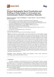
important figure is the moment of inertia of the rotor which ranges from 3 to 11 Kg*m2 [2]. T-zero choppers spin at angular velocities ranging from 20 Hz (1200 RPM) to 60 Hz (3600 RPM). They must arrive at their top dead center position within 50 µs of the time the neutron pulse arrives at the chopper rotor. If this window is missed for any particular neutron pulse, the neutron scattering instrument must discard the data associated with that neutron pulse. This is called a veto event. Veto events reduce the efficiency of the neutron scattering instrument. The arrival time interval of the neutron pulse at the chopper rotor is constantly changing. The phase of the rotor must then be constantly accelerated and decelerated to track the phase of the neutron pulses. This phase command that the chopper must follow is plotted in figure 1 [3]. The plot shows phase drift with respect to a 60 Hz crystal clock.
1 INTRODUCTION
2 DESIGN CONSTRAINTS The rotating T-zero chopper is a massive rotor made of Inconel-750, steel, and aluminum. At LANSCE, these rotors can weigh as much as 500 lbs. and have diameters as wide as 28 inches. From a controls perspective, the
0-7803-7191-7/01/$10.00 ©2001 IEEE.
Phase Drift [rad]
2000
Neutron Choppers are electromechanical devices that remove unwanted energy components from the beam. Tzero choppers rotate a large mass through the beam to effectively place a beam stop in the path of the beam and eliminate high-energy neutrons that occur early in the neutron pulse. We must operate these choppers in phase with the production of neutrons so that the energy distribution in each neutron pulse in the instrument remains constant. Since power modulators in the LANSCE accelerator must be phase locked to the AC power grid, the production of neutrons is also tightly coupled to the phase of the grid. This situation requires that the massive neutron choppers also be phase locked to the power grid. There is, however, some tolerance on how tightly the power modulators must be phase locked to the grid. In an effort to make the changing phase of the accelerator easier for the choppers to follow, this phase lock of the LANSCE timing reference generator has been loosened as much as possible [1]. This improved high-speed chopper performance, but the coupling between the accelerator and the grid is still so tight that this effort had a negligible effect on T-zero chopper performance.
1000 0 -1000 0
20
40
60
80
100
Time [h]
Figure 1: 90 hours of phase drift data. The drift is measured with respect to an ideal 60 Hz source. The drift is substantial, 1500 radians corresponds to 240 cycles. The challenge for the chopper is to follow these changes through acceleration and deceleration.
3 DESIGN The chopper controller is designed to couple the phase of the chopper’s rotor to the phase command produced by the timing reference generator. A block diagram of the controller, its relationship to the timing reference generator, and the motor - load combination is shown in Figure 2. The timing reference generator produces a signal that the controller interprets as both a velocity feed forward, ωcff(t), and a phase command, θc(t). The motor - load combination produces signals corresponding to the present velocity, ω(t), and phase, θ(t), of the rotor. The controller calculates the difference between the present
1438
Proceedings of the 2001 Particle Accelerator Conference, Chicago
ωcff (t ) Raw Power Grid
Timing Reference Generator
θ c (t )
+
+
θ e (t ) -
ω c (t ) +
ω c∆ (t ) + -
PID
ω e (t )
PID
ic (t )
Rotor
Motor
ω (t ) θ (t ) Controller
Figure 2: Architectural block diagram. the best results have been obtained with the derivative term set to zero. For example, the two controllers that are presently in operation are set so that Ki = 0.17 [sec-2], Kp = 1.5 [sec-1], and Kd = 0 in their phase control loops. Plugging in these numbers yields the actual transfer equation (2).
G ( s ) = 1 .5 +
The phase control circuit is a digital system with a sample rate of 120 Hz. The continuos transfer function in equation (2) must be transformed into the z-domain so that it may be implemented digitally. The z-transformed version of equation (2) appears in equation (3) as H(z).
H ( z) =
Ki/s
+
Kp
Figure 3: PID compensator block diagram. Ki is the integral gain and is shown in the diagram multiplied by 1/s where s is the Laplace operator or the complex frequency variable. The derivative gain is Kd and shown multiplied by s and the proportional gain is simply Kp. The transfer equation appears in equation (1).
K G (s) = K p + i + K d ⋅ s s
(1)
Although the phase controller fully implements all three terms, proportional, integral, and differential, in practice
1.5 + 1.416 ⋅10 −3 ⋅ z −1 − 1.499 ⋅ z −2 1 − z −2
(3)
Where z is the discrete complex frequency variable z=esT, and T is the sample period. This is the discrete time equivalent to equation (2). Both G(s) from equation (2) and H(z) from equation (3) are plotted on the same graph in figure 4. Magnitude Resp.
Kd*s
(2)
4.1 Digital Transfer Function
4 DIGITAL PID COMPENSATOR It is the PID compensator that is at the heart of phase control circuit. The compensator operates on the difference between the command and the actual values also known as the error signal. A block diagram of the PID compensator appears in figure 3 [4].
0.17 + 0⋅s s
30 25 20 15 10 5 0 0.001
0 -0.5 Mag[G(f)] Mag[H(f)]
-1
Ph[G(f)]
-1.5
Ph[H(f)]
Ph Resp.[Rad]
rotor phase, θ(t), and the command phase, θc(t), and calculates an error phase, θe(t). The error phase is operated on by a proportional - integral - differential (PID) compensator to produce a velocity command delta signal, ωc∆(t). This signal is added to the velocity feed forward signal, ωcff(t), to produce the velocity command signal, ωc(t). The controller calculates the difference between the present rotor velocity, ω(t), and the velocity command, ωc(t), to produce a velocity error signal, ωe(t). Another PID compensator is used to produce a current command signal, ic(t), which is then sent to the motor. The proportional, integral, and differential gains were chosen for the tightest possible stable coupling between the rotor and the timing reference generator. The controller is the section of the block diagram that is enclosed by the dashed line. It is implemented as a combination of analog and digital circuitry, a digital signal processor, and software.
-2 0.01
0.1
1
10
frequency [Hz]
Figure 4: The continuos time transfer function G(s) plotted with the discrete time transfer function H(z). G(s) and H(z) are plotted in terms of their magnitude and phase response
1439
Proceedings of the 2001 Particle Accelerator Conference, Chicago From figure 4, it can be seen that the discrete transfer function closely approximates its continuos time counterpart.
4.2 Difference Equation The transfer equation, H(z), is actually implemented as the difference equation (4). The variable n is the individual sample number.
y[n] = x[n] ⋅1.5 + x[n − 1] ⋅1.416 ⋅ 10 −3 − x[n − 2] ⋅ 1.499 + y[n − 2]
(4)
5 PERFORMANCE The phase command input to the chopper controller is made up of a series of pulses with a frequency of approximately 120 Hz, originating from the LANSCE timing reference generator [5] [6]. These pulses correspond to the point in the 60 Hz power grid cycle that crosses through zero volts. They do not appear at exactly 120 Hz because the phase of the power grid is always changing.
40 µs/div
15 µs
The bottom trace in figure 5 is from the magnetic pickup on the chopper rotor. The top trace is one of the 120 Hz phase command pulses. The scope is triggered from the bottom trace. With the scope set to infinite persistence, the various arrival times of the chopper at its TDC position are recorded between the markers on the top trace. The markers are 15 µs apart, so the worst case arrival time error encountered in this 2000 revolution test was ±7.5µs. The offset from the rising edge of the bottom trace to the rising edge of the top trace is intentional and corresponds to the time of flight from the point at which the neutrons are produced to the time they arrive at the chopper. But figure 5 does not tell the entire story, it only shows the worst case errors. The histogram or distribution of the same data in figure 5 is shown in figure 6. The distribution shows that most of the errors are much lower than ±7.5µs. The standard deviation (σ) is about 2.6 µs. So approximately 68% of the time the chopper arrives on target to within 2.6 µs.
6 FUTURE DEVELOPMENT The phase controllers that are presently in use at LANSCE are in rack mounted chassis with all user control taking place through the front panel. This system has been redesigned as a 6U VME board for use with the EPICS control system. As a VME board working with EPICS, the phase controller will have the added flexibility of having its user controls accessed through a remote networked Graphical User Interface (GUI). Phase controller operating status will also be available over the network, allowing the LANSCE control room operators to observe and selectively control neutron choppers.
7 REFERENCES Figure 5: Error time is shown as the width of the top trace.
Figure 6: Distribution of arrival time errors. When the chopper rotor passes through it’s top dead center (TDC) position, a magnetic pickup generates a pulse. On any given revolution of the chopper, the change in the elapsed time between the command pulse and the TDC pulse tells us how well the chopper is performing. This change in elapsed time is called the "error time". In figure 5, the worst case error times are observed by viewing the command pulse and the TDC pulse on an oscilloscope set to infinite persistence.
[1] Rybarcyk, L.J.; Shelley, F.E., Jr., “Improvements to the LANSCE accelerator timing system,” 1997 Particle Accelerator Conference, May 1997, Vancouver, BC. [2] Mark Taylor, Los Alamos National Laboratory, private communication. [3] R. Nelson, R. Merl, C. Rose, "Timing Reference Generators And Chopper Controllers For Neutron Sources", ICANS-XV, November 2000. [4] Chi-Tsong Chen, "Control System Design: TransferFunction, State-Space, and Algebraic Methods, Harcourt Brace Jovanovich College Publishers, 1993. [5] C. Rose, P. Lara, R. Merl, R. Nelson “A TimingReference Generator for Power-Grid-Synchronized Neutron-Spallation Facilities”, 2001 Particle Accelerator Conference, June 2001, Chicago, IL. [6] C. Rose, “DSP-Based Timing-Reference Generator User’s Guide, Version 2.0”, Los Alamos National Laboratory, January 2001, LA-UR-01-0419.
1440