International Journal of Control and Automation Vol.8, No.3 (2015), pp.1-8 http://dx.doi.org/10.14257/ijca.2015.8.3.01
Design and Simulation of Fractional Order Control Systems Based on Bode’s Ideal Transfer Function Duan- yuan Bai1, Chun- yang Wang1 and Ji Zou2 1
Changchun University of Science and Technology, Changchun City, Jilin Province, China 2 Electronic and Information Engineering College Changchun University Changchun City, Jilin Province, China3
[email protected];
[email protected] Abstract The fractional order calculus theory and its modeling methods have been applied widely in control field. And design of fractional order control systems become hot point of recent years. This paper establishes fractional order systems which parameters are obtained by Bode’s ideal transfer function method to get the desired frequency response. Apply this method a new control structure of fractional order pseudo-derivative feedback (FOPDF) is suggested. Control methods are designed for integral first order system and for fractional first order system, and apply to a real high power semiconductor laser diodes constant temperature controlling system and the hydraulic servo systems and the electric drive system, the simulation results indicate that the effectiveness and validity of this method. Keywords: fractional order control system; Bode’s ideal transfer function, high power Semiconductor Laser Diode, robustness, Al-Alaoui+CFE
1. Introduction Fractional calculus deals with derivatives and integrals to an arbitrary order. There are several definitions of fractional derivatives and integrals, the most fundamental definition of a fractional derivative and integral of order is given by Grünwald-Letnikov definition [1, 3, 5], Grünwald-Letnikov (GL) definition is given as: t a ] h
(1) f (t jh) h 0 j 0 j ( 1)...( j 1) ! Where, . j! j !( j )! j When 0 , means is derivative order of f (t ) ;when 0 ,mean is integral order of f (t ) . This definition is wildly used in control field [5]. [
a
Dt f (t ) lim h
(1)
j
Design the fractional controller is a main researching area of fractional calculus applying in the control field. And there are many kinds of methods to design a fractional order PID (FOPID) controller, including the phase margin, the amplitude margin, dominant pole method, optimization method, and the Bode’s ideal transfer function method. The Bode’s ideal transfer function method is easy and effective. It suggested an ideal shape of the open-loop transfer function of the form [5]:
ISSN: 2005-4297 IJCA Copyright ⓒ 2015 SERSC
International Journal of Control and Automation Vol.8, No.3 (2015)
Gopi( s ) c , R s
(2)
where ωc is the gain crossover frequency, In fact, the transfer function
Gopi( s ) is a
fractional-order differentiator for 0 and a fractional-order integrator for 0 . Its Open-loop characteristics are as follows: (1) Amplitude-frequency curve is is a straight line of constant slope−20 dB/dec; (2) Phase curve is a horizontal line at− π/2 rad; (3) The Nyquist curve consists, simply, on a straight line through the origin with argGopi(jω)=− π/2 rad.
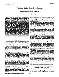
a) Frequency and Phase Curves When Fix
=11/9
and Changing ωc
b) Frequency and Phase Curves when Fix ωc =10rad/s, and Changing
Figure 1. Frequency and Phase Curves When Parameter Changing Figure 1 indicate that if the gain changes ωc, will changes together but the phase margin of the system remains as a independent value as m ( - 2/)rad[5].In this paper we applied the Bode’s ideal transfer function method to the determine the parameters of the FOPID system for integral first order system and fractitional first order system. The procedures of design FOPID system (1) Choosen the controlled plant and its transfer function GP ( S ) ; (2) Assume gain crossover frequency ωc, the phase margin Φm;Work out the transfer function of FOPID controller as (3)
Gc ( s )
Gopi( s ) GP ( S )
(3)
(3) Using impulse invariance method get the discretization model of Gc ( s ) and the simulation block of FOPID controller, Schematic Diagram is as Figure 2 [13].
2
Copyright ⓒ 2015 SERSC
International Journal of Control and Automation Vol.8, No.3 (2015)
initialization r=r+1,u=u+1 Take the sampling time Ts r
7Ts & 8
Caculate
r
Ts r *n (r-1) & gamma(r)
Caculate
7Ts 8
iteration,obtain
s r & su
u
Ts u *n (u-1) gamma(u)
Obtain
u
Gc ( z )
End
Figure 2. Schematic Diagram of the Controller Discretization Process
λ μ Figure 3. The Simulation Block of Fractional PI D Controller
(4) Simulate base on Matlab software, and get the unit step responses of the system, analysis dynamic performances. Pseudo-derivative feedback (short for PDF) control system introduced by Phelan in 1977 [15], this system is simple yet effective. PDF structure provides all the control aspects of PID control, but without system zeros that are normally introduced by a PID compensator. Phelan named this structure "Pseudo-derivative feedback (PDF) control from the fact that the rate of the measured parameter is fed back without having to calculate a derivative. The PDF structure internalizes a pre-filter, one would apply to cancel the zeros introduced in the PI (or PID) equivalent system [17]. The PDF structure is usually introduced into the design of electro-hydraulic servos [16], automatic control systems of electric traction [16], it offers a good disturbance rejection performance and promotes the response speed. In this paper the fractional PID algorithm is introduced into FOPDF systems to promote the property of fractional PID control system,the simulation results to a first-order controlled plant illustrate that the FOPDF control method has superior performances to IOPDF structure. The basic structure of IOPDF is as Figure 4.
R( s )
-
GcIOPI ( s )
1 Ts 1
Ki s
-
C( s )
Kd
Figure 4. The Basic Structure of IOPDF System
Copyright ⓒ 2015 SERSC
3
International Journal of Control and Automation Vol.8, No.3 (2015)
And using Bode’s ideal transfer function for FOPDF system should use step (5) to determine the control structure and parameters. (5) According to the basic structure of IOPDF,establish the FOPDF control system model γ to a first-order controlled plant 1/(Ts+1), 1/(Ts +1), the model for integer plant is shown in Figure 5. We suggest a basic structure of FOPDF system like Figure 5, where, the FOPI maybe a single FOPI controller or combined by FOPI controllers. The parameter Kd can be tuned of Chenliu method [17], as a basic tuning parameter of design FOPDF control structure. The Kd value is 5.44.Then the internal-loop can be treated as a whole controlled object. The equivalent open-loop block diagram of Figure 5 is shown in Figure 6. From Figure 6 the transfer function of FOPI controller designed based on Bode’s ideal transfer function can be expressed as (4):
c G (s) s GcFOPI ( s ) opi c [ Ts ( K d ) s ] G pop( s ) Ts K d
(4)
Figure 5. Block Diagram of FOPDF Control System Aimed to Integer First-order Control Object
R( s )
1 Ts 1
GcFOPI ( s )
K
d
C( s )
Internalloop
Figure 6. Open-loop Block Diagram of FOPDF Control System Aimed to Integer First-order Control Object
2. Establishing Fractional Order Control System Model 2.1. Establishing FOPID Controller Model Aimed at Integer First-Order Control Plant Assume the open-loop transfer function of control object is as (5):
GP1 (s)
1 Ts 1
(5)
here, T=0.4s, hypothesisΦm=70o, ωc =10rad/s.
4
Copyright ⓒ 2015 SERSC
International Journal of Control and Automation Vol.8, No.3 (2015)
As procedures (2), the transfer function of controller aimed at integer first-order control plant based on Bode’s ideal transfer function can be get from formula (6) : Gc1 ( s ) .s s GP ( S )
Gopi( s )
(6)
The simulation model of FOPID controller aimed at integer first-order control plant is shown in Figure 7.
Figure 7. Simulation Model of FOPID Controller Aimed at Integer First-order Control Plant 2.2. Establishing FOPDF Controller Model Aimed at Integer First-Order Control Plant Assume T is 0.4s, the expected crossover frequency ωc is 10 rad/s, the phase margin Φm is 70 ,then equation of the controller can be determined as (7): o
GcFOPI ( s ) [ 0.s
.s
]
(7)
Establishing FOPDF control system simulation model as Figure 8.
Figure 8. The Simulation Block of FOPDF Aim to Integer First-order Plant Control System 2.3. Establishing FOPDF Control System Model Aimed at Fractional First-Order Control Plant Assume the open-loop transfer function of control object is (8):
GP2 (s)
1 Ts 1
(8)
here, T=0.5s, 0.5 hypothesisΦm=70o, ωc =10rad/s.
Copyright ⓒ 2015 SERSC
5
International Journal of Control and Automation Vol.8, No.3 (2015)
As procedures (2) ,the transfer function of controller aimed at fractional first-order control plant based on Bode’s ideal transfer function can also be get from formula (9) : Gc2 ( s ) .s s GP ( S )
Gopi( s )
(9)
The simulation model of FOPID controller aimed at fractional first-order control plant is shown in Figure 8.While the subsystem block of FOPID controller and Fractional Order system are designed of the simulation blocks shown in Figure 3 applying the parameters in equation (8), (9).
Figure 9. Simulation Model of FOPID Controller Aimed at Fractional First-order Control Plant 2.4. Establishing FOPDF Control System Model Aimed at Fractional First-Order Control Plant For 1/(Tsγ+1),assume γis 0.5,T is 0.4s,(the other parameters are same as integer first-order control plant) ,the FOPDF structure is the same as integer one, but the equation of the controller is expressed as (10):
Gc FOPI ( s ) [ 0.s
.s
]
(10)
Figure10. The Simulation Block of FOPDF Aim to Fractional First-order Plant Control System
3. Simulation and Result Analysis Unit Step Responses with open-loop system gain K varying (0.9K,K,1.1K) are shown in Figure 11. Figure 11 shows that the controllers designed based on Bode’s ideal transfer function have both robustness anti-to the variation of system open-loop gain.
6
Copyright ⓒ 2015 SERSC
International Journal of Control and Automation Vol.8, No.3 (2015)
a)Unit Step Responses of Integer First-order First-order Control Plant
b) Unit Step Responses of Fractional Control Plant
Figure 11. Unit Step Responses of FOPID Controller The parameter of Kd can be tuned to a suitable value to get a desirable step response. The bode diagram of open-loop FOPDF system both for integer or fractional first-order plant are the same, is shown in Figure12 a). Figure 12 b) is partial enlarged unit step responses of FOPDF control system of integer first-order plant, when changing the system gain K. And Figure 12 is unit step responses of FOPDF control system of fractional first-order plant, when changing the system gain K.
a)Partial Enlarge Unit Step Responses of FOPDF Control Structure Aim at Integer First-order Plant
b) Unit Step Responses of FOPDF Control Structure Aim at Fractional First-order Plant
Figure 12. Unit Step Responses of FOPDF Control Systems
4. Conclusions With the Bode’s ideal transfer function method, we obtain closed-loop systems robust to gain variations and the step responses indicating an iso-damping property. And the calculating process is fairly easy to traditional fractional order controller design methods. But, it must be noted that the characteristic has limitation to the gain crossover frequency ωc and that the phase margin of the resulting closed-loop system is not exactly identical to the prescribed value defined by the slope at that frequency. This is due to realize a arbitrary order by physical facilities are usually not easily. Simulations illustrate that the order can be confirmed easily, but the select of ωc must consider a lot. To obtain a good performance, ωc
Copyright ⓒ 2015 SERSC
7
International Journal of Control and Automation Vol.8, No.3 (2015)
must be as high as possible. And if too high this will hardly to get the PID parameters. And in this paper, we also have presented a new strategy of FOPDF control structure and apply Bode’s ideal transfer function method, Chenliu method for parameters tuning. The numerical performances indicate that FOPDF control may result in a more rapid, more accurate and more robust control system. FOPDF method which has iso-damping property is of the practicability and effectiveness. FOPDF control method is likely applied in first order or first order time lag system like the hydraulic servo systems and the electric drive systems, high power semiconductor laser diodes constant temperature controlling systems.
References [1] K. B. Oldham and J. Spanier, “The Fractional Calculus: Theory and Application of Differentiation and Integration to Arbitrary Order”, Academic Press, New York, (1974). [2] I. Podlubny, “Fractional Differential Equations”, Academic Press, San Diego, California, (1999). [3] A. Oustaloup and P. Melchior, “The great principles of CRONE control[C]//International Conference on Systems, Man and Cybernetics: vol.2. Piscataway, NJ, USA: IEEE, 1993: 118-129. [4] I. Podlubny, “Fractional-order systems and PIλDμcontrollers [J]”, IEEE Transactions on Automatic Control, vol. 44, no. 1, (1999), pp. 208-214 [5] R. S. Barbosa, J. A. Tenreiro Machado and I. M. Ferreira, “Tuning of PID controllers based on Bode’s ideal transfer function [J]”, Nonlinear Dynamics, vol. 38, nos. ½ , (2004), pp. 305-321. [6] Y. Q. Chen, C. H. Hu and K. L. Moore, “Relay feedback tuning of robust PID controllers with iso-damping property”, in the Proceedings of the 42nd IEEE conference on Decision and Control, Maui, Hawaii, December 9–12, 2003,pp. 2180–2185. [7] Y. Q. Chen, T. Bhaskaran and D. Y. Xue, “Practical tuning rule development for fractional order proportional and integral controllers [J]”, Journal of Computational and Nonlinear Dynamics, vol. 3, no. 2, (2008), 020201.1-021404.7. [8] C. Wang, Y. Luo and Y. Chen, “An Analytical Design of Fractional Order Proportional Integral and [Proportional Integral] Controllers for Robust Velocity Servo”, In Proc. of The 4th IEEE Conference on Industrial Electronics and Applications, Xi'an, China, (2009) May 25-27. [9] Y. Luo, Y. Q. Chen, C. Wang and Y. Pi, “Tuning Fractional Order Proportional Integral Controllers for Fractional Order Systems”, Journal of Process Control, vol. 20, no. 7, (2010) August, pp. 823-831. [10] C. Wang, Y. Jin and Y. Chen, “Auto-tuning of FOPI and FO [PI] Controllers with Iso-damping Property”, 48th IEEE Conference on Decision and Control and 28th Chinese Control Conference (CDC/CCC), Shanghai, China, (2009) December 16-18. [11] L. Ying, C. Wang and Y. Chen, “Tuning Fractional Order Proportional Integral Controllers for Fractional Order Systems”, In Proc. of the 21st Chinese Control and Decision Conference (CCDC), Guilin, China in (2009) June 17-19. [12] C. Wang, Y. Luo and Y. Chen, “Fractional Order Proportional Integral (FOPI) and [Proportional Integral] (FO [PI]) Controller Designs for First Order Plus Time Delay (FOPTD) Systems”, In Proc. of The 21st Chinese Control and Decision Conference (CCDC), Guilin,China in (2009) June 17-19, pp. 329-334. [13] C. Wang, “Study on Fractional Order PIλ Dμ Controller Parameter Tuning Methods and Design Phd Thesis”, Jilin University, (2013). [14] H. Yan, “A Design Method of the Parameters of Fractional-order PIλDμ Controller Poles-Orders Searching Mehod”, Information and Control, vol. 36, no. 4, (2007) August. [15] R M. Phelan, “A SIMPLIFIED APPROACH TO FEEDBACK CONTROL SYSTEM DESIGN”, ComellUniversity, Ithaca, Newyork, (1978). [16] W. Zeng and S. Fu, “Speed Electro-hydraulic Servo Pseudo-differential Feedback control system”, Hydraulic and Pneumatic”, vol. 12, (2002). [17] L. Chen, “Robust Behavior of Subvariable Control of Pseudo Derivative Feedback Algorithm”, ASME Paper No.89-WA/DSC-16 (1989). [18] M. Borrello, “Controls”, Modeling and Simulation, http://stablesimulations.com/technotes/pdf.html,2005
8
Copyright ⓒ 2015 SERSC