DESIGN, DEVELOPMENT, AND COMMISSIONING OF A 120 kN DEADWEIGHT FORCE STANDARD MACHINE Andy Knott National Physical Laboratory, United Kingdom
ABSTRACT This paper describes the development of a 120 kN deadweight force standard machine and its commissioning in late 2003 / early 2004. The rationale for developing a machine of this capacity is given together with details of its design, focusing in particular on the scalepan and weightstack arrangements. The calibration of the masses is described and an uncertainty budget for the force generated by the machine, resulting in an expanded uncertainty of ±0,001 %, is given. Information on the construction of the machine is also given, as are details of the control system. The results of comparison tests between the machine and NPL’s other deadweight machines, carried out as part of the commissioning procedure, are described. The conclusion is made that the machine will be suitable to act as the pilot machine in a forthcoming CIPM 100 kN Key Comparison.
1.
BACKGROUND
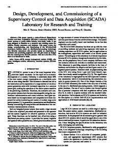
With the move of NPL’s force standards to a new laboratory building, it was decided to dispose of an old 50 kN machine and replace it with one of a capacity which fell better within the range between the newer 20 kN and 1.2 MN machines (see Figure 1). A survey of calibration work was carried out and the procurement of a 120 kN machine - which could calibrate transducers of 25 kN, 30 kN, 40 kN, 45 kN, 50 kN, 55 kN, 60 kN, 80 kN, 100 kN, and 120 kN capacities in ten fairly equal steps – was proposed. 1.2 MN machine 120 kN machine 20 kN machine 50 kN machine 120 kN common forces 50 kN common forces
1
10
100
1,000
Force / kN Figure 1: Deadweight machine common forces
2.
DESIGN
When designing a deadweight machine of a given capacity, it is important to keep the first increment of force as small as possible, as this is the determining factor in the range of transducer capacities which can be calibrated solely within the machine (BS EN ISO 376 - the
1
latest international calibration standard for force transducers - allows valid classifications down to 2 % of the maximum calibration force). However, this force increment (or scalepan) needs to be both strong enough to support the maximum force and large enough to enable transducers of various geometries to be accommodated. These are conflicting requirements, so a compromise has to be arrived at. For the 120 kN machine, it was decided that the scalepan would apply a force of 2,5 kN and that the working volume would be maximised by using a single beam scalepan (with the tension space above and compression space below) rather than a double beam scalepan (with an intermediate earth support), as had been the case with the 50 kN machine (see Figures 2 and 3).
Figure 2: Old 50 kN machine, 120 kN machine schematic, and 120 kN machine scalepan
Figure 3: Views of 120 kN machine
2
A scalepan generating a force of 2,5 kN corresponds to a value of 2,1 % of the machine’s total capacity – this is similar to the 20 kN machine’s scalepan (2,5 %) but significantly greater than those of the 1,2 MN machine (0,8 %) and 2,5 kN machine (1,0 %). However, it was felt that this was a price worth paying to obtain a large compression working volume, bearing in mind that calibrations can be carried out in more than one machine. This volume (770 mm high, 530 mm diameter) was maximised by designing the machine with a single weightstack and the scalepan to locate with the weightstack’s top weight, removing the need for scalepan components to be present over the height of the weightstack. The machine incorporates a single stack of 23 weights, in addition to the scalepan, generating forces of only three different values – 2,5 kN (the top eleven weights), 5 kN (the next six weights), and 10 kN (the bottom six weights). This enabled a high degree of commonality, and hence a reduction in cost, in their design and manufacture. All weights are made from 304S11 austenitic stainless steel – this material was selected for its long-term mass stability and its low magnetic permeability. Unlike NPL’s 2,5 kN and 20 kN machines, in which the weights are suspended from each other using pins in hangers on the outer faces, it was decided to follow the approach used in the 1,2 MN machine, in which the weights are supported on horizontal faces, using conical lead-ins to ensure precise positioning. This was to reduce stresses and bending in the weights, and to make accurate machining of the weights easier. To ensure equal loading, each weight is supported (when at rest) on the one below - and, when applied to the transducer, from the one above – by three hanger assemblies. These assemblies are equidistant from the centre of the weight and arranged at 120º intervals – alternate weights have these assemblies staggered by 60º. The hanger arrangement and some of the hanger components are shown in Figure 4.
Figure 4: Weightstack components and details
3
3
CALIBRATION AND UNCERTAINTY
On 12 August 2003, the local value of acceleration due to gravity was determined by the British Geological Survey (BGS). BGS made relative gravity measurements between various NPL locations, including one next to the 120 kN machine and another where the absolute value of gravity had previously been determined (to be 9,811 816 90 m·s-2 ± 0,000 000 05 m·s-2) by NPL. The resultant calculated value for the 120 kN machine location (9,811 818 47 m·s-2 ± 0,000 000 06 m·s-2 at a height of 120 mm above ground level), together with (1), enabled the conventional mass values required to generate forces of 2,5 kN, 5 kN, and 10 kN to be calculated – 254,833 0 kg, 509,666 0 kg, and 1 019,332 0 kg respectively, at this height. As the masses are situated at different depths within a pit, a corrected conventional mass value was calculated for each one, using a gravitational acceleration gradient of 0,29 × 10⁻⁶ m·s-2·m-1. F = mc g (1 – 1,2 / 8 000 + (1,2 - ρa) / ρm)
(1)
where: F is the downward force on the transducer, in N mc is the conventional mass value of the mass, in kg g is the acceleration due to gravity, in m·s-2 ρa is the air density, in kg·m-3 ρm is the density of the mass, in kg·m-3 The six 10 kN masses were calibrated on NPL’s 2,7 tonne mass comparator, and the six 5 kN masses and the twelve 2,5 kN increments (eleven masses and the scalepan) on NPL’s 500 kg weight exchanger (Figure 5).
Figure 5: 2,7 tonne mass comparator, operational schematic of the mass comparator, and 500 kg weight exchanger
Following the weighings, each mass was adjusted to within 1,3 ppm of its target value, with an uncertainty of 2,0 ppm (at a 95 % level of confidence). The other major uncertainty contribution to the generated force is the variation in atmospheric air pressure, leading to changes in air density and hence buoyancy force. This adds an uncertainty contribution of 3,0 ppm (at a 95 % level of confidence) and, when combined with the effects of mass stability, variation in gravity, and aerodynamic and magnetic forces [1], leads to an expanded uncertainty of under 6,0 ppm. This value is then combined with an allowance of 5,0 ppm for force introduction effects to give a final expanded uncertainty of less than 8,0 ppm for each weight. The machine is certified to generate forces accurate to ±0,001 %, at a 95 % level of confidence.
4
4
INSTALLATION AND CONTROL SYSTEM
The machine is situated in a 4,35 m deep pit, so that the working area is conveniently at ground level and next to the working areas of the 2,5 kN and 20 kN deadweight machines. This pit, and the installation of the weights, can be seen in Figure 6.
Figure 6: Weight installation
As with NPL’s three other deadweight machines, the 120 kN machine has a control system which allows it to be operated either manually or under PC control. Similar Visual Basic® software has been written for the four machines – this will either (in manual mode) simply display the status of the machine or (in active mode) give the operator full control of the machine. Screenshots of the control system software can be seen in Figure 7.
Figure 7: Screenshots from the 120 kN machine software, in active control mode
5
5
COMMISSIONING AND INTERNAL COMPARISONS
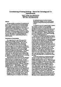
The machine design is such that there are twelve forces common to it and the 1,2 MN machine, five forces common to it and the 20 kN machine, and one force common to it and the 2,5 kN machine. As part of the commissioning exercise, in-house comparison exercises were carried out between the 120 kN machine and these three other machines, and the results of these comparisons are shown in Figure 8.
Cells in 120 kN machine
0,003 %
Cell 72397 in 2,5 kN machine Cell 72397 in 20 kN machine
0,002 %
Cell B11354 in 1,2 M N machine Difference from mean deflection in 120 kN machine
Cell 42139 in 20 kN machine
0,001 % 0,000 % -0,001 % -0,002 % 0
20
40
60 Force / kN
80
100
120
Figure 8: Comparisons between the 120 kN machine and the other three deadweight machines
6
CONCLUSIONS
It is important, for the sake of international trade agreements, regulation, and fair competition, and to reduce technical barriers to trade, that measurements and tests made in one country are internationally accepted. To support this aim, the Comité International des Poids et Mesures (CIPM, or International Committee for Weights and Measures) has initiated a series of Key Comparisons to compare the values of standards being realised at national metrology institutes, such as NPL, around the world. In the area of force, the 120 kN machine will be used in 2005 and 2006 as the pilot machine in the CIPM 100 kN Key Comparison, an exercise involving the national laboratories of seventeen other countries, from five continents. The care put into the development of the machine and its resulting performance should ensure that the forces generated at the pilot laboratory throughout the exercises will be stable and repeatable.
REFERENCES [1] A. J. Knott, “The accuracy of the NPL 1,2 MN deadweight force standard machine”, Proceedings of the 14th IMEKO TC3 International Conference, Warszawa, Poland, 1995, pp. 86-90. Address of the author: Andy Knott, National Physical Laboratory, Hampton Road, Teddington, Middlesex, United Kingdom, TW11 0LW. E-mail:
[email protected]. © Crown copyright 2004. Reproduced by permission of the Controller of HMSO.
6