October 2, 2011 19:51 RPS/INSTRUCTION FILE
0005
International Journal of Aerospace and Lightweight Structures Vol. 1, No. 1 (2011) 119–132 c Research Publishing Services
DOI: 10.3850/S2010428611000067
DESIGN, FABRICATION AND HOVERING PERFORMANCE STUDY OF NANO COAXIAL ROTOR
ZHEN LIU1,2,a∗ JEAN-MARC MOSCHETTA1,b and MIN XU2 1 Department
of Aerodynamics, Energetics and Propulsion, Institut Sup´ erieur de l’A´ eronautique et de l’Espace, University of Toulouse 31055, France. a
[email protected], b
[email protected]
2 Department
of Astronautics, Northwestern Polytechnical University, Xi’an, 710072, China.
[email protected] Accepted 6 September 2011
A nano coaxial rotor was designed, fabricated and studied experimentally at an ultralow Reynolds number ranging from 5000 to 20,000. The Minimum Induced Loss theory was employed to optimize the geometry of nano coaxial rotor with the introduction of weights to take into account the interference of upper rotor and lower rotor. The chord and twist distributions of both rotors were achieved as a result. Nano coaxial rotor was then fabricated with a lightweight material of carbon laminate. Two rotor slices were obtained with mass less than 0.3 g and the thickness less than 0.23 mm. Successively, a sensitive test bench was designed to measure the hovering performance of nano coaxial rotor. Single upper rotor and lower rotor were tested with the test bench as well as the isolated upper rotor and lower rotor of nano coaxial rotor. It is found that the designed nano coaxial rotor can generate a thrust of 0.105 N with torque cancelled. And the comparison between single rotor and isolated rotor of nano rotor showed that the mutual interaction between rotors improves upper rotor performance but impairs lower rotor performance. Keywords: Nano Air Vehicle; Nano coaxial rotor; Design and fabrication; Hovering performance.
1. Introduction Nano Air Vehicles (NAVs)[Pines, 2005] was proposed by the Defense Advanced Research Projects Agency (DARPA) as an unmanned aerial robot allowing reconnaissance inside buildings, penetration of narrow entries and transmission of data without being detected and required for both military and civil applications. It is a new conceptual controllable unmanned air vehicle which can hover and fly at low speed with dimension less than 7.5 cm and weight lower than 10 grams. Coaxial rotor ∗ Corresponding
author. 119
October 2, 2011 19:51 RPS/INSTRUCTION FILE
120
0005
Zhen Liu, Jean-Marc Moschetta and Min Xu
configurations process the advantages of compactness, high payload-carrying ability, and high hovering performance within the size and weight constraints. Therefore, this study draws attention to the design, fabrication and validation of nano coaxial rotor with optimized hover ability. The design of the rotor is the essential part of the propulsive system design, especially for small rotary-wing UAVs. However, the design of nano rotor is scarcely studied due to its small size and low rotational speed despite of the fact that the design of micro or conventional full-scale rotor [Leishman, 2000] is well studied. Bohorquez [2007] designed a coaxial rotor of conventional blade with a diameter of 22.4 cm. The blade tip shape, blade solidity and blade airfoil were investigated with a single rotor bench to obtain a high FM [Bohorquez et al., 2003]. However, the design did not take into account the interference between the upper rotor and the lower rotor. Kroo [2000]and Kim [2004] used the conventional Minimum Induced Loss theory (MIL) proposed by Larrabee [1979] to design teetering rotor. The design of teetering rotor based on optimization methods has been well studied since last century. Adkins [1994], Rzik [1986] and Kroo [1984] improved this method and utilized it on more issues. However, modern optimization methods, such as multidisciplinary design optimization (MDO), genetic algorithm (GA) and evolutionary algorithm (EA), provide more choices for rotor optimization. Gur [2009] adopted the MDO method to design a propeller which can satisfy the requirements of thrust, power, acoustics and structure. Luo [2003] utilized GA method to optimize a propeller by parameterizing it with two three-order Bezier curves. Traditional optimization method is capable of achieving a single-objective optimization results but always obtains the theoretical results while neglecting other factors. Modern optimization methods can solve multi-objective problems easily but with the sacrifice of efficiency. Furthermore, the smooth geometric form might not be achieved because of multi-objectives in some cases. Nano coaxial rotor requires a small mass and a high strength, so lightweight material shall be used. Carbon laminate, plastic and fiberglass are widely utilized to fabricate small rotors [Bohorquez et al., 2003]. Experiment is an important means to study the performance of nano coaxial rotor. With the reduction of size and rotational velocity, nano coaxial rotor operates in a significantly low Reynolds number ranging from 5000 to 20,000 accompanying with the phenomena of separation, transition and reattachment. It is found that the thrust and the torque of the rotors are significantly small of the order of 0.010 N and 0.001 N·m, respectively, representing critical parameters for a typical NAV. Coupling between torque and thrust makes the measurement sensitive to the test fixtures. Moreover, the interference between upper rotor and lower rotor increases further the difficulty of measurement. Therefore, measuring both thrust and torque simultaneously is a significant challenge. Bohorquez [2007] developed a simple stand with load cell and torque sensor to test the hovering performance of micro coaxial rotor with diameter of 22.4 cm. The experiments were performed on micro coaxial
October 2, 2011 19:51 RPS/INSTRUCTION FILE
0005
Design, Fabrication and Hovering Performance Study of Nano Coaxial Rotor
121
rotor with different collective angles combinations over a range of rotational velocities. He [2009] conducted the studies of a gearless torque-canceling coaxial propeller by measuring torque and thrust separately. Schafroth et al. [2009] designed a test bench with a torque sensor and tension load cell to measure the total thrust and torque of coaxial rotor with radii from 5 cm to 7 cm. Either the stand is too insensitive to utilize on nano coaxial rotor, or thrust and torque are measured separately. Therefore, a new test bench shall be designed which allows the measurement of tiny force and torque simultaneously of nano coaxial rotor. In this paper, nano coaxial rotor with teetering blades was designed and fabricated for NAVs and the hovering performance of it was studied experimentally. Firstly, the nano coaxial rotor was designed with MIL optimization methods by taking into account the interference between upper rotor and lower rotor. In view of the importance of hover flight, the minimum of hovering performance was taken as the optimization objective. In succession, the moulds of nano coaxial rotor were designed and fabricated. Carbon laminate and resin epoxy were utilized as the lightweight material to fabricate rotors. After the fabrication of nano coaxial rotor, a sensitive test bench was designed with a beam load cell and a torque sensor to study the hovering performance of nano coaxial rotor experimentally at an ultra-low Re. In order to study the interference between upper rotor and lower rotor, experiments were conducted by comparing the performance of isolated upper or lower rotors with single rotor.
2. Design and Fabrication Methodology 2.1. Design methodology 2.1.1. Objective of design To solve the problem of significant propulsive performance degradation of nano coaxial rotor due to its small size and low rotational speed, the design of nano coaxial rotor was performed based on hovering efficiency in this study. The objective of the rotor optimization is to reduce the energy loss as much as possible. A pair of nano coaxial rotor with a diameter of 7.5 cm and a minimum total thrust of 0.120 N shall be designed according to the definition of NAV. The rotational speed is about 6500 RPM and the rotor hub is 0.2 radius of rotor. The airfoil utilized for the blade is a thin arc airfoil with a maximum camber of 5% at 0.5 chords and a thickness of 0.2%. The aerodynamic performance of the airfoil shall be calculated at several different ultra-low Res to apply in the optimization. 2.1.2. Optimization methods The optimization of coaxial rotor focused on the teetering rotor design instead of conventional full-scale helicopter rotor design. This study designed the nano coaxial rotor with MIL theory at a freestream velocity of zero, i.e. in hover. Larrabee [1979]
October 2, 2011 19:51 RPS/INSTRUCTION FILE
122
0005
Zhen Liu, Jean-Marc Moschetta and Min Xu
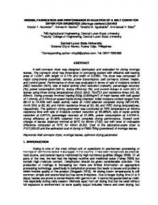
pointed out that there is a certain variation of circulation along the lifting lines minimizing the energy loss in the wakes of rotor. This circulation is defined by a certain Goldstein loading which results in the constant displacement velocity v ′ along the blade radius. Therefore, the objective of the optimization is to find the appropriate distributions of blade chord and pitch angle so that the constant displacement velocity can be obtained with the specified thrust, torque and rotational speed. In this study, the combination of the optimization methods proposed by Larrabee [1979] and Adkin [1994] was used to design nano coaxial rotor. Firstly, the displacement velocity shall be determined. At a differential annulus, the flow passing by the blade section at radial station r is illustrated in Fig. 1. The induced velocities of v1 and v2 can be represented with freestream velocity and rotor rotational speed. v1 = V · a and v2 = Ω r a′
(1)
′
where terms V , Ω, a and a are freestream velocity, rotational velocity, axial interference factor and radial interference factor, respectively. In terms of the momentum theory, the thrust T and the torque Q were calculated based on the conservation of momentum across the rotor disk. The thrust and the torque at a differential annulus can be expressed as dT = 4πrρV 2 (a + a2 )F dr,
(2)
dQ = 4πΩr3 ρV (1 + a)a′ F dr.
(3)
where ρ is the air density. The original formulas were derived from the incompressible Bernoulli equation neglecting the effect of the swirl velocity, the viscous and pressure drag. The momentum loss factor F is therefore introduced to correct the equation based on Prandtl tip loss theory. If the blade is divided into infinitesimal sections, the blade elements can then be assumed as a quasi-2D section with mutual influence of adjacent blade element. Hereafter, the sectional airloads of each blade element are calculated separately, and the aerodynamic performance of rotor can be achieved by integrating the aerodynamic forces and moments along the blade. The thrust and torque in the annulus of
Fig. 1.
Flow passing by blade section at radial station r.
October 2, 2011 19:51 RPS/INSTRUCTION FILE
0005
Design, Fabrication and Hovering Performance Study of Nano Coaxial Rotor
123
rotor disc can also be expressed as the function of circulation Γ and the flow angle φ at the annulus. dT = 2πrρW F v ′ cos φ sin φ(cos φ − C d /Cl sin φ)dr
(4)
dQ = 2πr2 ρW F v ′ cos φ sin φ(sin φ + C d /Cl cos φ)dr
(5)
where W , φ, Cd and Cl are flow velocity passing by blade element, helix angle, drag coefficient and lift coefficient of airfoil at blade station r. Since the thrust and the torque in the annulus are unique, Eq. (2) and Eq. (3) shall be equivalent to Eq. (4) and Eq. (5). Hereby, the interference factors can be expressed as, ( v′ · cos2 φ (1 − C d /Cl tan φ) a = 2V (6) v′ ′ a = Ωr · cos φ sin φ(1 + C d /(Cl tan φ)) From the equations Eq. (5), the filament helix angle φ can be represented with the freestream velocity, the rotor rotational speed and induced velocity whether the viscosity is included or not. tan φ =
V v′ + Ωr 2Ωr
(7)
In light of Betz condition, the energy loss is minimum while the value of r tan φ equals to zero along the blade. Therefore, v ′ shall be a constant for the whole blade. The objective of the optimization is to obtain the chord and angle distribution to generate a constant v ′ . Thus, the thrust and the torque in the annulus are the functions of displacement velocity by integrating equation dT and dQ along the radius. Z R 2πrρW F v ′ cos φ sin φ(cos φ − C d /Cl sin φ)dr (8) T = R0
Q=
Z
R
2πr2 ρW F v ′ cos φ sin φ(sin φ + C d /Cl cos φ)dr
(9)
R0
The blade is divided into N elements and every element is assumed to be a very small segment with constant flow parameters to approximate the integration. Airfoil aerodynamic parameters at different Reynolds numbers were calculated prior to the optimization so that the lift coefficient and the drag coefficient can be calculated at arbitrary angle of attack with CFD method. At each element, the Reynolds number can be calculated from the following formula. Re =
4πrρF cos φ sin φv ′ Cl NB µ
(10)
The drag-to-lift ratio C d /Cl of blade element may be determined with the Re and a choice of lift coefficient.
October 2, 2011 19:51 RPS/INSTRUCTION FILE
124
0005
Zhen Liu, Jean-Marc Moschetta and Min Xu
With the specified thrust or torque (relating with power), blade number, radius, hub radius, station number, freestream velocity, blade element aerodynamic parameter, rotational speed and the initial lift coefficients distribution along the blade, the displacement velocity can be calculated. After several iterations, the result may be obtained. Finally, the blade chord and the twist angle are obtained. 2.1.3. Optimization procedure In the procedure of the coaxial rotor design, the induced velocity of one rotor will be recorded as additional axial and rational velocity components of freestream of the other rotor. However, the interaction between rotors depends on their spacing and rotational direction. The axial and radial weights are therefore defined to present the magnitude of the influence of one rotor to the other. The product of weights and axial or radial induced velocity of one rotor will be taken as the freestream velocity of the other rotor so that the coaxial rotor can be designed based on this input of freestream velocity. Since both rotors rotate in a reverse direction with small spacing less than 2 R, weights of 1.0 for axial velocity and −1.0 for radial velocity are specified to reflect the influence of the upper rotor induced flow to lower rotor. The products of weights and corresponding induced velocities of upper rotor are integrated with the freestream velocity of lower rotor as a final input condition to design the lower rotor. And the induced velocity of lower rotor can then be calculated. Similarly, the induced flow of lower rotor will influence the upper rotor as well. An axial weight of 0.5 and a radial weight of 0 are specified to account for the influence of the lower rotor induced flow to the upper rotor. The products of the weights and induced velocities of lower rotor are then introduced in the freestream velocity of upper rotor. Thus, the upper rotor is designed with the freestream. Iterations will stop when no change can be found for chord and twist angle along the blade for both rotors. 2.2. Fabrication methods According to the geometry of nano coaxial rotor, two sets of mould are to be designed and fabricated for upper rotor and lower rotor. Each set of mould is composed of four parts: The first part has the convex surface identical to the lower surface of rotor; the second part has the concave surface identical to upper surface of rotor; and the other two parts are two components to fix the first part and the second part. Due to the constraint of NAV weight, the fabrication shall decrease the mass of both rotors as low as possible while the basic geometry of nano coaxial rotor shall be ensured. Carbon laminate has the advantages of low density and high solidity appropriate to be employed on nano coaxial rotor fabrication. Two layers of carbon fiber with thickness of 0.102 mm will be attached on the moulds in a crossed position with the epoxy resin to ensure the homogenous characteristics in various directions.
October 2, 2011 19:51 RPS/INSTRUCTION FILE
0005
Design, Fabrication and Hovering Performance Study of Nano Coaxial Rotor
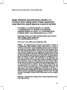
Fig. 2.
125
Test bench based on torque sensor.
3. Experiment 3.1. Experimental set-up A nano-coaxial-rotor test bench mainly constructed by a torque sensor and beam load cell was developed as shown in Fig. 2. The beam load cell is F1200 sized at a capacity of 0.5 N from calculated estimates. The hovering torque sensor is DH15 from the SCAIME company with a capacity of 0.005 N·m and accuracy class of 0.2%. Torque sensor was secured on an aluminum beam which is strictly horizontal. Extended supporting beams were installed on the torque sensor to avoid the blockage of the torque sensor to the rotor wake. At one end of supporting beam, beam load cell was fixed horizontally. Additionally, a long carbon tube was equipped vertically at one end of the beam load cell to support the motor and rotor to be tested. Another motor and rotor are fixed right above the rotor to be tested with a long carbon tube. The position of this rotor can be well adjusted so as to test the coaxial rotor at the right rotor spacing. Once the thrust is generated by the rotor to be tested, it will be detected by beam load cell when the torque acts on the hovering torque sensor via the vertical aluminum supporting beam. Thus, the thrust and torque of one rotor can be measured simultaneously under the influence of the other rotor. After the measurement of this rotor, the other rotor shall be switched on the beam load cell and the same test condition shall be kept. As a result, the propulsive performance of both rotors is achieved. The speed measurement system was a speedometer which was able to emitter and receive laser. It was fixed just under the rotor. Hereby, rotational speed could be measured and then transferred to the data acquisition system. Thick wires were adopted to connect the electronic
October 2, 2011 19:51 RPS/INSTRUCTION FILE
126
0005
Zhen Liu, Jean-Marc Moschetta and Min Xu
devices on the test bench to reduce inner resistance of the whole circuit. The electric parameter measurement system consists of an ampere meter and a voltmeter to measure the current and voltage passing through the controller. The controller was YGE4-BL2 from Wes-Technik for brushless motors. All output signals were transferred to a PXI-1050 chassis for processing. Via a front module PXI-8336, PXI-1050 chassis is connected through an optical cable to a Dell Optiplex 330 PC with 1.98 GB RAM. The PC runs Measurement and Automation Explorer (MAX) as driver interface between control software, LabView, and the PXI-1050. A command generated by Measurement and Automation Explorer (MAX) and Labview was input in NI PXI-6229 series which could transformed this digital signal into a analog signal transmitting to the speed controller, and the measurements acquired during the experiment (voltage, current, thrust, torque and rotational speed) were relayed back to the MAX and Labview as well. 3.2. Experiment design Since the torque sensor and 0.5 N beam load cell are two primary sensors to measure the performance of nano coaxial rotor, calibrations of test bench are necessary to eliminate the error introduced by the non-linear property of sensors and electronic wires. Detailed test bench calibrations were carried out before experiments to improve the precision of results. In order to take into account the hysteresis property of both sensors, loads are applied firstly and then they are unloaded. After the calibrations of torque sensor and 0.5 N beam load cell, the propulsive performance of single rotor was firstly measured without the interference of another rotor. Then the propulsive performance of each rotor of nano coaxial rotor was measured at a rotor spacing of 1.07 R by fixing the rotational velocity of the upper rotor at 6,500 RPM, Reynolds number at 3/4 R of 15,000, and changing lower rotor rotational velocity with the input current from the Reynolds number of 6000–14,000. And the experimental results were compared with that of single rotor. The interaction between lower rotor and upper rotor was analyzed. The experiments were all carried out at a tension input to controller of 3.7 V which has the same value as the NAV battery. During the experiment, the rotational speed, input current, input voltage, the thrust and the torque of each rotor were measured. 4. Results and Discussion 4.1. Rotor optimization results The optimization result of nano coaxial rotor was achieved when solution converged after six iterations and there were no changes for chord and twist angles. In the end, an upper rotor with mean chord of 0.33 R and mean twist angle of 17.21◦ and a lower rotor with mean chord of 0.31 R and mean twisted angle of 17.67◦ were obtained (Fig. 3).
October 2, 2011 19:51 RPS/INSTRUCTION FILE
0005
Design, Fabrication and Hovering Performance Study of Nano Coaxial Rotor
(a) Fig. 3.
127
(b)
Blades chord and twist distribution: (a) upper rotor, (b) lower rotor.
The nano coaxial rotor was finally designed. The analytical method was utilized here to design nano coaxial rotor. This method requires the input of the aerodynamic parameters of blade airfoil which are interpolated with the computational results obtained with CFD method. This method has a good precision without stall of airfoil and has been validated [Adkins, 1994]. And the rotor geometries can be obtained efficiently comparing with the other optimization method. However, the unsteady aerodynamic effects which are significant at ultra-low Re were not taken into account in the design due to the application of the analytical method. 4.2. Rotor geometry Two sets of moulds were designed as shown in Fig. 4. The function of every part is stated in section 2.2. With these moulds, rotors were fabricated as shown in Fig. 5. The mass of each rotor is less than 0.3 g and the thickness is found less than 0.23 mm. Due to the constraint of the fabrication method, the geometry of fabricated rotor differs from that of optimum rotor. The thickness of the blade is nearly constant resulting in the change of airfoil at different stations. The fluidity of the epoxy resin also causes the imbalance of distribution because of the gravity. 4.3. Experimental results Calibrations of beam load cell (thrust) and torque sensor (torque) are shown in Fig.6. In the figure, the thrust applied and torque applied are the known mass or torque added on the test bench, while thrust measured and torque measured are quantities measured by the test bench. One-order polynomial functions (straight lines) were fitted respectively so that a relationship between the measured value
October 2, 2011 19:51 RPS/INSTRUCTION FILE
128
0005
Zhen Liu, Jean-Marc Moschetta and Min Xu
(a)
Fig. 4.
(b)
Moulds for nano coaxial rotor: (a) upper rotor, (b) lower rotor.
Fig. 5.
Nano coaxial rotor.
(a) Fig. 6. Calibration of test bench: (a) thrust, (b) torque.
Fig. 6.
(b)
Calibration of test bench: (a) thrust, (b) torque.
October 2, 2011 19:51 RPS/INSTRUCTION FILE
0005
Design, Fabrication and Hovering Performance Study of Nano Coaxial Rotor
129
and real value could be established. However, fitted functions introduce errors into the results. The relative fit error is defined as the ratio of the difference between the real value added on test bench and the fitted value obtained from the function to the real value. It is found that the relative fit error for thrust is very low and the hysteresis property of test bench is very weak. Therefore, fitted functions are appropriate to give a reasonable precision for results and test bench shows a good performance. The hovering performances of single upper rotor and lower rotor were firstly studied experimentally at ultra-low Res. And the hovering performance of coaxial rotor was studied successively. Comparisons were performed between single rotor and isolated rotor of coaxial rotor to understand influence of rotor interaction to the rotor performance by virtue of experiment as illustrated in Figs. 7 and 8. It is found the thrust of single upper or lower rotor increase with the increase of Reynolds number. And the maximum thrusts of upper rotor and lower rotor are 0.146 N and 0.112 N, respectively. Lower rotor generated a higher thrust than the upper rotor at the same Reynolds number. On the other hand, the maximum thrust of the isolated upper rotor and that of isolated lower rotor of nano coaxial rotor are 0.067 N and 0.055 N. The total thrust of coaxial rotor is 0.105 N when both rotors rotated at a velocity of 6500 RPM, that is the Re of upper rotor is 14,900 and the Re of lower rotor is 12,700. When comparing single rotor and isolated rotor of coaxial rotor, the single upper rotor generated a thrust slightly higher than that of the upper rotor of coaxial rotor at the same Re, while the single lower rotor generated a thrust fairly higher than that of the lower rotor of nano coaxial rotor at the same Re. However, the difference between the experimental thrust of single lower rotor and the lower
(a) (b) Fig. 7. Comparison between the isolated rotor of coaxial rotor and single rotor by virtue of experiments: (a) Fig. 7. Comparison between the isolated rotor of coaxial rotor and single rotor by virtue of experiments: (a) thrust, (b) torque.
October 2, 2011 19:51 RPS/INSTRUCTION FILE
130
0005
Zhen Liu, Jean-Marc Moschetta and Min Xu
Fig. 8.
Comparison of F M between the isolated rotor of coaxial rotor and single rotor.
rotor of coaxial rotor decreases with the increase of Re, and the experimental thrust of lower rotor of coaxial rotor exceeded that of single lower rotor at a certain Re. It is evident that the induced flow of upper rotor has a negative effect on the thrust of lower rotor at low Re but a positive effect at high Re. The experimental results for torque exhibit nearly the same trend. The total torque of coaxial rotor is 2.84×10⁻⁵ N·m which states that the torque is nearly canceled. The torque of upper rotor of coaxial rotor is identical to that of single upper rotor at the same Re while the torque of lower rotor of coaxial rotor is lower than that of single lower rotor and the discrimination increases with the reduction of Re. Because of the interaction, the F M of the upper rotor of coaxial rotor increased while the F M of the lower rotor of coaxial rotor decreased when comparing with single upper and lower rotor as illustrated in Fig. 8. It is detected that F M s of single upper rotors vary from 0.55 to 0.63 while those of lower rotors are less than 0.3. F M s of the isolated upper rotor of a coaxial rotor range from 0.65 to 0.75 whereas those of the isolated lower rotor of a coaxial rotor are from 0.2 to 0.25. Herein, the interaction of upper rotor and lower rotor improves the performance of upper rotor but degrades the performance of lower rotor. Leishman etc. [2006] found that the F M of upper rotor of a full-scale coaxial Mono Tilt Rotor (MTR) approximates to 0.7 and that of lower rotor is 0.45. It can be found that the peroformance of upper rotor of nano coaxial rotor approaches that of full-scale MTR, whereas the performance of lower rotor of nano coaxial rotor is lower than that of full-scale MTR. However, results of both kinds of coaxial rotor indicate that the performance of upper rotor is prior to that of lower rotor due to the interference between upper rotor and lower rotor. The study of micro coaxial rotor (Bohorquez [2007]) showed similar conclusion.
October 2, 2011 19:51 RPS/INSTRUCTION FILE
0005
Design, Fabrication and Hovering Performance Study of Nano Coaxial Rotor
131
5. Conclusion The performance of propulsive system of NAV has a direct impact on the flight performance of NAV. In this paper, a nano-coaxial rotor propulsion set was designed, fabricated and studied experimentally. As the main component to generate lift and thrust, the propulsive performance of nano coaxial rotor determines the flight performance of NAV. So, the objective of design is to obtain a nano coaxial rotor of high propulsive performance with the other constraints such as diameter, thrust and rotational velocity etc. Then, nano coaxial rotor was designed based on MIL theory. Weights were introduced to take into account the mutual interference of upper rotor and lower rotor during the design. The products of weights and the induced flow velocities of one rotor were combined with the freestream velocity of the other rotor to optimize the rotor. After a few iterations, the distributions of chord and twist of nano coaxial rotor were then obtained. An upper rotor with mean chord of 0.33 R and mean twist angle of 17.21◦ and a lower rotor with mean chord of 0.31 R and mean twisted angle of 17.67◦ were obtained. It is found that the nano coaxial rotor has larger chords and higher twist angles than micro rotor or full-scale rotor. Finally, the rotor was fabricated with carbon laminates. The nano coaxial rotor fabricated has thickness of 0.23 mm and mass of less than 0.3 g. Confined by the fabrication technique, the form of each rotor varies slightly from that of optimized rotor. The experimental study of the hovering performance of nano coaxial rotor was carried out. The hovering performance of single rotor was measured without the interference of another rotor as well. Comparisons were performed between the hovering performance of isolated rotor of nano coaxial rotor and single upper rotor or lower rotor to investigate the interaction between upper rotor and lower rotor. Results showed that the value of thrust of nano coaxial rotor is higher than 0.1 N and the value of torque of nano coaxial rotor is nearly zero with both rotors at 6,500 RPM. The comparisons between the isolated rotor of coaxial rotor and single rotor showed that the propulsive performance of upper rotor augmented while that of lower rotor degraded. The figure of merit of the lower rotor increased with the increase of the thrust coefficient to rotor solidity ratio and the best figure of merit for the upper rotor (0.65–0.75) was higher than the value for the lower rotor (0.23). In conclusion, nano coaxial rotor of large chords and high twist angles along the blade was well designed and fabricated with composite materials. The propulsive performance of designed coaxial rotor was fine to provide the sufficient thrust for NAV. The mutual interaction between rotors improves upper rotor performance but impairs lower rotor performance.
Acknowledgments The authors would like to thank China Scholarship Council and the laboratory of the Department of Aerodynamics, Energetics and Propulsion, Institut Sup´erieur de
October 2, 2011 19:51 RPS/INSTRUCTION FILE
132
0005
Zhen Liu, Jean-Marc Moschetta and Min Xu
l’A´eronautique et de l’Espace for the financial and facilities support. They would also like to thank R´emy Chanton, Guy Tessarotto, and Serge G´erard for their help on the test bench fabrication.
References Adkins, C. N. [1994] “Design of optimum propellers,” Journal of Propulsion and Power 10(5), 676–682. Bohorquez, F. [2007] “Rotor hover performance and system design of an efficient coaxial rotarywing Micro Air Vehicle,” Ph.D. thesis, Department of Aerospace Enginering, University of Maryland, Maryland. Bohorquez, F., Samuel, P. and Sirohi, J. et al., [2003] “Design, analysis and hover performance of a rotary wing Micro Air Vehicle,” AHS Journal 48, 80–90. Gur, O. and Rosen, A.[2004] “Optimization of propeller based propulsion system,” Journal of Aircraft 46(1): 95–106. He, R. and Sato, S. [2008] “Design of a single-motor nano aerial vehicle with a gearless torque-canceling mechanism,” 46th AIAA Aerospace Sciences Meeting and Exhibit, AIAA paper, 1417. Kim, G. B., Paik, I. H. and Yoon, K. J. et al. [2004] “Manufacturing and Performance Testing of Rotary Wing-type Micro Air Vehicle,” AIAA 3rd Unmanned Unlimited Technical Conference, Workshop and Exhibit, AIAA paper, 6333. Kroo, I. [1984] “Propeller-wing integration for minimum induced loss,” Journal of Aircraft 23(7), 561–565. Kroo, I. and Kunz, P. [2000] “The mesicopter: aminiature rotorcraft concept,” Stanford Univeristy Report. Larrabee, E. E., [1979] “Practical Design of Minimum Induced Loss Propellers,” SAE Paper 790585, Society of Automotive Engineers, 1979. Leishman, J. G. [2000] Principles of helicopter aerodynamics (CambridgeUniv. Press, New York). Leishman, J. G. and Ananthan, S. [2006] “Aerodynamic Optimization of a Coaxial Proprotor,” 62nd Annual National Forum of the American Helicopter Society, Vol. 1, Phoenix, AZ, 64–86. Luo, D. M., Zhou, J. and Ang, H. S. [2003] “Aerodynamic Optimization Design of Micro Air Vehicle Propeller,” Jouranl of Nanjing University of Aeronautics and Astronautics 35(3), 322–325. Pines, D. J. [2005] “06-06 proposer Information Pamphlet (PI) for Defense Advanced Research Project Agency (DARPA) Defense Sciences Office (DSO) Nano Air Vehicle (NAV) program,” DARPA DSO, 1–24.. Rizk, M. H. [1986] “Propeller design by optimization,” AIAA Journal 24(9), 1554–1556. Schafroth, D., Bouabdallah, S. and Bermes, C. et al., [2009] “From the test benches to the first prototype of the muFly micro helicopter,” Journal of Intelligent & Robotic System 54(1): 245-260.