That means that at a particular computing node, only messages of in- terest have to be processed by software; other messages are discarded by hardware and ...
Design of a Real-Time CORBA Event Service customised for the CAN Bus Rainer Finocchiaro, Stefan Lankes, Andreas Jabs Lehrstuhl f¨ur Betriebssysteme, RWTH Aachen, Kopernikusstr. 16, 52056 Aachen, Germany E-mail: {rainer, stefan, jabs}@lfbs.rwth-aachen.de Abstract Real-Time Corba and minimumCORBA are the foundations many so called distributed real-time embedded (DRE) systems are built upon. These specifications describe middleware suitable for connecting different parts of a complex embedded system. Efficient group based communication in such a system can be achieved by using the Event Service. This article focuses on the design of such a service complying to the OMG Event Service standard. It is optimised for the CAN bus, a widely used interconnect, where real-time characteristics are a requirement. A new protocol for the efficient distribution of events in a CAN-based distributed control system is presented, a protocol which is tailored to the CAN bus and produces very low overhead by utilising CAN-specific features. Keywords: Real-Time CORBA, Controller Area Network (CAN), distributed real-time embedded (DRE) applications, Event Service
1 Introduction Control systems in automotive, manufacturing and aerospace industries have to fulfill tasks of increasing complexity. All these systems provide growing safety and comfort functionality. For example, today, more and more automobiles are equipped with safety systems like ABS (Anti Blocking System), ESD (Electronic Skid Detection), automatic gearboxes, systems ensuring the correct distance to the surrounding traffic, and comfort utilities like multimedia systems and air conditioning. In oder to implement these systems in a cost-effective way, small specialised and inexpensive functional units, such as sensors, actuators, and processing units, are combined into a distributed system. This distributed approach is
furthermore preferred over a setup of a single highly powerful general purpose computing unit, as it facilitates implementation of fault tolerance. Unfortunately, this distribution of functional units comes at a cost: development of software for distributed systems is inherently more complex than it is for centralised systems. To cope with this increasing software complexity and to facilitate programming of distributed systems in general, middleware has been developed. General purpose middleware like CORBA, Java/RMI and DCOM has some drawbacks when used in Distributed Real-time Embedded (DRE) systems [14]: it usually has a high memory footprint (some Object Request Brokers (ORB) require several megabytes of memory) and offers poor real-time functionality. To address these problems, ROFES - a real-time CORBA ORB for DRE systems (see http://www.rofes.de) - has been developed at the Chair of Operating Systems [6]. The ORB itself enables point-topoint communication between remote objects. Communication in distributed systems that predominantly exchange sensor data is rarely limited to two communication partners. Often, a varying number of functional units is interested in data from a varying number of sensors. Point-to-point communication badly represents the needs of the above mentioned systems. A more decoupled communication scheme, where producers and consumers of data do not have to know about each other, is provided by the CORBA Event Service [9]. This article elaborates on an implementation of the CORBA Event Service specification, which is customised for operation over the CAN bus (Controller Area Network) [1]. The CAN bus is a widely-used real-time control network that features broadcasting as its native addressing scheme. This implementation of the Event Service makes extensive use of the CAN bus features in order to provide real-time characteristics and allow resource conscious delivering of event data from producers to consumers.
0-7695-2132-0/04/$17.00 (C) 2004 IEEE
The article is organised as follows: Section 2 briefly introduces the technical background and terminology. Section 3 presents the actual implementation of our Event Service, while section 4 gives more detail about the protocol used for communicating events over the CAN bus. Section 6 concludes the status of the developed implementation of the Event Service and gives an outlook into future extensions.
2 Technical Background 2.1 Basic CAN Features The Controller Area Network (CAN[12]) is an ISO defined serial communication bus. It was originally developed during the 80’s by Robert Bosch GmbH for the automotive industry. Because of its robustness against all electric influences and its error detection capability, it is widely used in automotive, manufacturing and aerospace industries. The CAN bus works according to the ProducerConsumer-Principle: messages are not sent to a specific destination address, but rather as a broadcast (aimed at all receivers) or a multicast (aimed at a group of receivers). A CAN message has a unique identifier, which is used by devices connected to the CAN bus to decide whether to process or ignore the incoming message. For that purpose, CAN bus interface cards offer one or more programmable mask registers, which allow filtering of messages based on the CAN message identifier at hardware level. That means that at a particular computing node, only messages of interest have to be processed by software; other messages are discarded by hardware and do not affect the processing resources. There are two variants of the CAN Protocol: The main difference between CAN 2.0A and CAN 2.0B is that the former uses 11 bits to uniquely identify each message, while the latter uses 29 bit identifiers. For correct operation of the CAN bus, the identifiers of two messages sent at the same time must never be the same. As a consequence, CAN 2.0B offers greater flexibility regarding message IDs, at the cost of blocking the bus for a longer time, thus deteriorating response times. The CAN bus protocol uses the Carrier Sense Multiple Access arbitration scheme with Collision Avoidance (CSMA/CA). This collision avoidance is achieved by careful selection and interpretation of the identifier bits. During the arbitration process, any node willing to send a CAN message starts sending bit by bit the 11 (or in case of CAN 2.0B, the 29) identifier bits. Each time a bit is applied to the bus, the sending node checks whether the bus adapts to the corresponding voltage level – high for an applied logical 1 and low for an applied logical 0. If any one of the attached nodes applies a logical 0, the whole voltage level of the bus is drawn to low - this be-
haviour is called Wired-And. The CAN Specification [12] therefore calls the logical 0 the dominant bit and the logical 1 the recessive bit. If the sending node detects a difference between the bit it sent and the voltage level of the bus, it backs off and loses this arbitration cycle. As soon as the bus is free again, it retries to send the same message. This arbitration process only works if messages have unique identifiers (the CAN Specification ensures this). As a consequence of this arbitration scheme, messages with a low identifier (i.e. starting with many zeros) have a high priority and are sent before messages with a lower priority. Because of these priorities, time guarantees for high priority messages can be given, which is a basic requirement for real-time operation (compare with section 4.5). This, together with its broadcasting nature, makes the CAN bus especially suited for a real-time Event Service.
2.2 Basic Real-Time CORBA Features To understand the interaction of our Event Service and Real-Time CORBA, this section explains the necessary features of the Real-Time CORBA specification. A more detailed description of the Real-Time CORBA specification is given in [11] and [13]. In general, extensions can be classified into those for management of processor resources and those for management of inter-ORB communication. For the management of processor resources, Real-Time CORBA specifies priority mechanisms, thread pools, standard synchronizers, and a global scheduling service. Managing inter-ORB communication comprises selection and configuration of protocol properties, and explicit binding, which is used in our interorb protocol for the CAN bus - CANIOP [7]. The extensions of importance for this work are the priorities associated with an invocation and the thread pools offering a standard way of programming threads in CORBA. The latter allow defining properties, such as the number of threads created initially, the maximum number of threads that can be created dynamically, and the threads‘ default priority.
2.3 Event Service With the Event Service [9], the OMG satisfies the demand for a more decoupled communication between distributed objects. Standard CORBA requests result in the synchronous execution of an operation by an object. These requests are directed to a particular object. In contrast to that, the Event Service allows for a looser binding between senders and receivers of requests. Participants of the Event Service no longer have to know with how many other objects they communicate, nor where those other objects are
0-7695-2132-0/04/$17.00 (C) 2004 IEEE
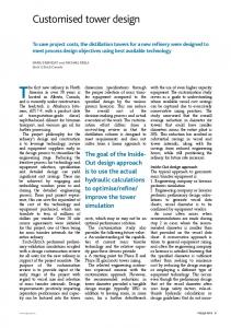
located; even more than that: they do not even have to know if these other objects exist at all. They just send their event data to or get it from the Event Channel – and do not have to care about the rest. The Event Service defines two roles for objects: the supplier role and the consumer role. Suppliers produce event data and consumers process event data. These two roles are both subdivided into an active and a passive model. • Suppliers (shown on the left-hand side in figure 1) can either actively push their produced event data to the Event Service – this is called the Push-Model – or passively wait until the Event Service pulls it from them (Pull-Model). • Consumers (shown on the right-hand side in figure 1), on the other hand, can actively pull event data from the Event Service (Pull-Model), or passively wait until the Event Service pushes it to them (Push-Model).
Event Service Push Supplier
Supplier Admin Pull Supplier
Proxy Push Supplier
Proxy Push Consumer
Proxy Pull Consumer
Event Channel
Push Consumer
Consumer Admin
Event Channel Factory
Proxy Pull Supplier
Pull Consumer
Event Flow Not part of the OMG Standard
push()
pull()
create()
Figure 1. Structure of the Event Service In the next subsections, the components of the Event Service – as shown inside the grey box in figure 1 – are described in greater detail in bottom-up order: Starting with the Event Channel Factory component, which is first created when setting up an Event Service, and continuing towards the proxies, which are created when connecting to a specific Event Channel. Section 2.3.6 presents a real-world example to demonstrate how all these components interact. 2.3.1 Event Channel Factory The Event Channel Factory is the first object to be created when setting up an Event Service. Its purpose is to offer an interface for the creation of Event Channels. With an Event Channel Factory running, it is possible for local and remote objects to create any number of Event Channels. Platformspecific details of Event Channel creation are hidden from the user of the Event Channel Factory.
2.3.2 Event Channel The Event Channel is created by the Event Channel Factory. It is the main component of the Event Service. Responsible for creation of administration objects, it keeps track of connected objects and multiplexes event data. All event data sent from suppliers to consumers passes through the Event Channel. 2.3.3 Administration Objects There are two administration objects: one is used by event consuming objects (Consumer Admin) and one by event producing objects (Supplier Admin). These admins are responsible for creating proxy objects for the Pull-Model and the Push-Model (i.e. the Supplier Admin creates ProxyPushConsumers and ProxyPullConsumers, whereas the Consumer Admin creates ProxyPushSuppliers and ProxyPullSuppliers). The administration object’s only purpose is proxy-creation, i.e. event data passing from suppliers through the Event Channel to consumers does not pass through the admins. 2.3.4 Proxies Proxies are the last objects created when connecting to the Event Channel. They are created by the administration objects. Each supplier and each consumer connects to exactly one proxy object. The proxy objects offer a consumer interface to the supplier and a supplier interface to the consumer, so that each object connecting to the Event Service has the impression of being connected to and communicating with only one partner. 2.3.5 Event Data The event data, which is sent by suppliers via the Event Channel to the consumers, has to be in the form of a CORBA::Any. This is a standard CORBA data type, which basically consists of the data itself (a series of bytes) and a Type Code containing information about how to interpret this data (e.g. as an integer, string, character or any other of the 32 CORBA defined data types). 2.3.6 Example Scenario The following real-world example is used to explain the purpose of the Event Channel and the interactions between its components: As depicted in figure 2, there is a sensor ready to send the oil temperature of a car engine to whatever component is interested (display, central computer, etc.), at a regular interval. Here, the sensor represents a Push Supplier as it actively wants to push its data (the temperature value) to the consumers. In contrast to that, Pull Suppliers would
0-7695-2132-0/04/$17.00 (C) 2004 IEEE
77°C
ProxyPush Consumer
EC
77°C Central ProxyPush Computer Supplier 77°C 77°C ProxyPush Temperature Supplier Display
Oil Temperature Sensor
would have to cross the rather slow network twice, when supplier, consumer and Event Service are not colocated, but reside all on different nodes. Exactly the latter scenario is the typical use case, when connecting multiple sensors with multiple sensor-data-consumers.
Node1
Figure 2. Oil Temperature Sensor pushing Event Data to Consumers
Event Channel Factory
PushSupplier
h()
wait passively until some interested component pulls the data from it (compare with figure 1). When the car is started, only the Event Service, which provides an Event Channel Factory interface, is started. The central computer uses the Event Channel Factory to create the needed oil-temperature Event Channel (this could in fact be done by e.g. the sensor, as well). After the specific Event Channel is set up, any consumer (central computer, the display, etc.) or supplier (here the sensor) can connect to it. Connecting is a three-step process which involves the other components, which have not been mentioned by now in this example (the administration objects and the proxies). A close look onto figure 1 is helpful to visualise the components referred to in the following listing: (1) The Event Channel is called to return a Supplier Admin. The Supplier Admin is responsible for creating ProxyPushConsumers oder ProxyPullConsumers. (2) The sensor calls the Supplier Admin to create and return a ProxyPushConsumer. (3) The sensor (or Push Supplier) connects to the ProxyPushConsumer. The connection from the supplier to the Event Channel is established. The central computer and the display (compare with figure 2) have to perform analogous actions on the consumer side (obtaining the admin and proxy and connecting). As soon as a consumer (e.g. the display) and a supplier (e.g. the sensor) are connected to the same Event Channel, the first real sending of data (e.g. the oil temperature) from suppliers to consumers can happen. As figure 2 shows, data is not pushed directly from the Push Supplier to the Event Channel. It is rather given to the Proxy first, then from the Proxy to the Channel, from the Channel to each registered Proxy, and from there it is finally pushed to the Push Consumers (or pulled by Pull Consumers).
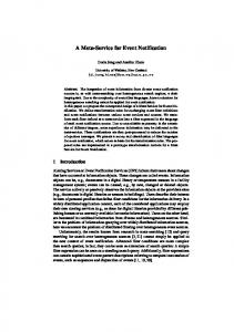
3 Implementation of the Event Service In contrast to a centralised Event Service (as depicted in figure 3), we chose a distributed approach as proposed by Kaiser [3]. With the centralised Event Service, event data
EC
()
pull
PullSupplier PullSupplier
PushConsumer
PushConsumer
pus
PullSupplier
PushConsumer
create_channel()
PushSupplier PushSupplier
pu sh ()
Event Service
push() pull()
pu
ll()
PullConsumer PullConsumer
PullConsumer push () pull()
Ethernet push(
()
PushSupplier
PushSupplier
push
PullSupplier ll() PullSupplier pu
)
pull()
Node2
PushConsumer
PushConsumer PullConsumer
PullConsumer
EC = Event Channel
Figure 3. Centralised Event Service The distributed Event Service (compare with section Federated Event Channels [2]) is an attempt to reduce the high amount of network traffic at the cost of higher setup complexity. Furthermore, it addresses the problem of unnecessarily high latency for event data sent from a supplier to a consumer on the same node. Node
Node
Supplier
Consumer
Supplier
Consumer
EC
EC
CanBusHandler
CanBusHandler
CAN Bus Figure 4. Distributed Event Service for the CAN Bus Figure 4 shows that every node in the network has its own Event Service with its own local Event Channel(s). In addition to the advantage of less network traffic, the behaviour in case of a failure of nodes is better. In the centralised setup, the Event Service represented a single point
0-7695-2132-0/04/$17.00 (C) 2004 IEEE
Consumer 1
EC
Supplier
Consumer 2 Consumer n
Figure 5. Multiplexing of Event Data The CAN bus, as the network used for this implementation, gives some additional advantages to the distributed setup: In general, Events have to be multiplexed as soon as there is more than one consumer connected to any channel. With point-to-point communication, which normal CORBA operations are based on, this multiplexing has to be performed by the Event Channel. One send-operation over each point-to-point connection to a consumer has to be performed (see figure 5). With its broadcasting nature, the CAN bus automatically multiplexes data: Every event data sent once on the CAN bus is received by the corresponding Event Channel on all listening nodes at the same time (see figure 6). 1
Multiplexing
n Node 1
EC
Consumer1
EC
Node 2 Consumer2
EC
Node n Consumer n
PushSupplier PushSupplier
PushSupplier
pu
sh
PullSupplier PullSupplier
()
PullSupplier ll() pu
transfer()
PushConsumer PushConsumer
PushConsumer
EC
pu
ll(
PullConsumer ) PullConsumer tra PullConsumer ns fe r() create_channel()
Event Channel Factory
Can Gateway send()
Node
Supplier
Node )
n
Multiplexing
sh(
1
This is not necessary with the CAN bus. In this case each Event Channel only has to be connected to the local CAN Bus Handler. The protocol ensures that each connected Event Channel receives its data. The disadvantage of this approach is, that an Event Service has to be started on each node, which leads to slightly higher resource requirements, because of the extra functionality present on each node. Figure 7 depicts the components present on every node in the distributed Event Service setup for the CAN bus (Event Channel Factory, CAN Bus Handler and CAN Gateway, Event Channel, and consumers and suppliers). These components interact in the following way: When starting the Event Service on this node, the Event Channel Factory and the CAN Bus Handler are created and the Event Channel Factory is ready to serve requests. The CAN Bus Handler is the component which is responsible for sending and receiving data over the CAN bus and for binding an Event Channel to an Event Channel ID (ECID) – see section 4.1 for further detail.
pu
of failure, whereas in the distributed case, failure of a node leaves the other nodes working as before.
EC
CAN Bus
Can Bus Handler canRead()
CAN Bus
canSend()
create
Event
Figure 6. Multiplexing of Event Data by CAN Bus
Figure 7. Components of Distributed CAN Event Service and their Interactions
The connection of distributed Event Channels is simplified when using the CAN bus in comparison to using standard point-to-point communication. Generally, using the distributed Event Service setup, a particular Event Channel - in our example for the ”Oil Temperature” - has to be set up on every node. With point-to-point communication, a link between these channels has to be set up explicitly: Each channel has to be connected to all the corresponding channels as a supplier of events and as a consumer, too.
With help of the factory, a specific Event Channel and a corresponding CAN Gateway are created. Each Event Channel has exactly one CAN Gateway attached to it, which is responsible for transferring event data via the CAN Bus Handler to any other Event Service listening on the CAN bus. After having created channel and gateway, any number of consumers and suppliers can connect to the channel locally and send or receive event data. Still, Events have to be exchanged between Event Channels over the CAN bus. Therefore, a protocol is necessary, which defines the com-
0-7695-2132-0/04/$17.00 (C) 2004 IEEE
munication between these Event Channels.
3. The node field contains the node number of the sending node. Four bits support a maximum of 24 = 16 different nodes. The node number serves two purposes:
4 CAN Event Broadcast Protocol The CAN Event Broadcast Protocol (CEBP) is a protocol defining communication between Event Channels, which are located on different nodes connected by a CAN bus. Like e.g. our CANIOP [7], DeviceNet [8], and other higher level protocols, the CEBP resides on top of the CAN Protocol (as defined in the Bosch standard [12]). It makes extensive use of the CAN identifier, which is described in section 4.1 and imposes a particular format on the data bytes carried by each CAN message (see section 4.2). The protocol is completely implemented in the CAN Bus Handler (see figure 7).
4.1 Structure of the CAN Message Identifier 11 Bit Identifier Protocol (2) Priority(2) Node(4) (x) Bitlength
ECID(3)
Data (0−8 Byte)
Figure 8. Identifier of a CAN Message (Version 2.0A) Figure 8 depicts the CAN message identifier for version 2.0A of the CAN bus protocol. The 11 bits are divided into the following four fields (from left to right):
(1) It guarantees that the same Event sent from different nodes never has the same identifier. As mentioned in section 2.1, this is a prerequisite for the correct operation of the CAN bus. (2) It allows the CAN Bus Handler to determine where a received Event comes from. This could later be used for filtering at the CAN bus interface card level. 4. The Event Channel ID (ECID) field allows to distinguish the subject of an Event. At the moment, system designers have to decide at setup time, which subject (e.g. oil temperature, or the amount of petrol in the tank) corresponds to which ECID. Later this binding of subjects should be performed by a binding daemon. The size of a system designed with CAN 2.0A identifiers is limited to four priority levels, 16 connected nodes and eight different Event Channels. Therefore, only small systems can be satisfied effectively with this setup. If more nodes, priorities or Event Channels need to be differentiated, version 2.0B of the CAN bus protocol can be used. In that case, the CEBP supports 256 priority levels, 128 connected nodes, and 4096 different events. This extended flexibility certainly comes at the cost of higher latency and a decrease in network performance in general.
4.2 Structure of the CAN Message Body 7
1. The protocol field comprises two bits and selects one of the four upper-layer protocols: 002 is the top priority protocol, reserved for system designers to implement their own functionality. CAN messages sent with this protocol have a higher priority than those of other protocols, thus giving system designers the highest flexibility. 012 selects the CAN Event Broadcast Protocol, which is described in this article. It is used to send Events to all listening receivers at once. 102 selects the point-to-point protocol CANIOP, which is used for standard CORBA communication over the CAN bus. This protocol is described in [7]. 112 will be used for a network management protocol. Connections between client and server or between the distributed Event Services will use this protocol. 2. The priority field offers four possible priority levels: 002 being the highest and 112 the lowest priority. The message with the highest priority wins the bus arbitration cycle (as described in section 2.1) and is sent first.
6
5
Identifier (11/29 Bit) FP LE TypeCode Byte 1
0
Data Length/Byte 7
Data (0−6 Byte)
Byte 2
Byte 3−8
FP = First Packet LE = Little Endian
Figure 9. Usage of Data Bytes in a CAN Message Figure 9 shows the CAN message identifier on the left, and the 8 data bytes each CAN message can transport, on the right. Of particular interest is the left-most of the 8 data bytes. It contains the 2 bits FP and LE, and the TypeCode of the sent CORBA data type: • FP means First Packet and indicates whether this message is the first in a series of CAN messages. Whenever a message is received, in which this bit is set, a new buffer is allocated on the receiver for concatenating the following messages, in order to reassemble the CORBA data type (see section 4.3). This field is also used in the detection of corrupted data, as explained in section 4.4.
0-7695-2132-0/04/$17.00 (C) 2004 IEEE
• LE stands for Little-Endian. This bit is set, when the sender’s processor architecture is little-endian. It is used by the receiver to decide whether the reassembled data has to be converted. • The TypeCode is a unique identifier defined in the CORBA Specification [10]. Up to version 2.6 of the CORBA Specification there are 34 different CORBA TypeCodes defined. This implementation of the CEBP provides a 6 bit field, supporting up to 26 = 64 different TypeCodes. For most of the CORBA data types, the TypeCode already is information enough to determine the length of the data type (i.e. a CORBA::Long is 4 bytes long). Having received the first CAN message, the receiver knows the total length of the data type and can calculate the number of CAN messages needed to reassemble the original CORBA data type. An exception to this rule are the string data types (CORBA::String and CORBA::WString): A string can have an arbitrary length. The TypeCode does not provide any information about the data length, in this case. Hence, for strings, the second byte in the first CAN message is used to store the data length. In subsequent messages this information is not needed anymore and the second byte is used to carry part of the actual data, again. As only one byte is used to store the length of a string, in this implementation the length of string data types is limited to 255 bytes. This does not comply with the CORBA standard. It has nevertheless been implemented this way for two reasons: (1) The CEBP loses complexity, and (2) this implementation of CORBA and the implementation of the Event Service is aimed at embedded systems, to which this should constitute a minor problem. Should it prove necessary to transfer strings longer than 255 bytes, in the future, this scheme could easily be extended to allow for unlimited string lengths.
4.3 Fragmentation and Reassembly In this section the CEBP’s handling of data types exceeding the length of 7 bytes is described. The CAN bus protocol allows a maximum of 8 data bytes in a single CAN message. In order to be able to send larger types, a higher layer protocol has to split them into a series of CAN messages at the sender and rejoin these messages on the receiving side. Splitting is called Fragmentation in network terminology and rejoining is called Reassembly. Figure 10 sketches this process for the CEBP. The sender passes the large data type to the CAN Bus Handler, which splits the data into 7 byte long units. Each of these units is accompanied by an information byte and then sent over the CAN bus. The information byte is described in section 4.2.
Sender CORBA::Any (35 Byte)
7 Byte
7 Byte CAN Packet (8 Byte) 8 Byte
8 Byte
8 Byte
8 Byte
CAN Bus Figure 10. Fragmentation of CORBA::Anys longer than 7 Bytes
At the side of the receiver, the whole process is inverted. The CAN message, which is marked as the first of a series, is received and joined with the following messages, which belong to the same data type. The reassembled data is then passed to the Event Channel. A scenario which is still to be described, is what happens if one (or more) of those CAN messages is lost somehow. Although this is extremely unlikely, as explained in section 2.1, provisions for detecting this have been made (see next section).
4.4 Detection of Corrupted Data This section describes the CEBP’s abilities to detect corruption of data due to message loss on the CAN bus. It will furthermore show the protocol’s reaction to such a loss. During development of the protocol, there were problems with corrupted data at the side of the receiver. Reasons for this were: (1) lost CAN messages, probably because of a broken CAN interface card, and (2) the simple fact that a node, which connects to the CAN bus during the transfer of a long data type, receives only subsequent messages (missing the first one(s)). The solution for synchronising the sending and receiving of Events, which is implemented in the CEBP, is based on the FP-bit described in section 4.2. When a long CORBA data type (i.e. spanning multiple CAN messages) is split into several CAN messages, the FP-bit of the first message is set to 1; for the subsequent messages belonging to that same data type, it is set to 0. The FP-bit is used as follows in the two error scenarios: • When a node is connected to the CAN bus in the middle of a data transfer, it receives only CAN messages with FP = 0. The node discards all messages with FP = 0 and waits until a new transfer is initiated (indicated by FP = 1). Normal operation starts then.
0-7695-2132-0/04/$17.00 (C) 2004 IEEE
• In case of message loss during transmission of a longer data type, the receiver does not get the expected number of CAN messages needed to reassemble the CORBA data type. At transmission of the next message from the same sender, the receiver gets a message with FP = 1, while still expecting a subsequent message with FP = 0. The receiver handles this scenario by resetting the receive buffer (thereby discarding the corrupted CORBA data type) and starts to reassemble the new CORBA data type. Summarising, corrupted data is detected as soon as a next first message of a data type is transmitted by the same sender and it is then simply discarded.
4.5 Response-Time Guarantees with the CEBP The CAN bus is an event driven bus and time guarantees for events are therefore not inherent. The system designer has to associate messages with priorities, so that with rate monotonic scheduling [5], the system becomes plannable. Due to the priority mechanisms, which the CAN bus provides (described in section 2.1), the in-time delivery of events can then be guaranteed up to the maximum allowed load.
5 Conclusions and Future Work Within the work described in this article, a light-weight implementation of the CORBA Event Service has been developed. It provides real-time extensions and is largely configurable. A protocol for the effective distribution of event data over the CAN bus has been developed and implemented. Event multiplexing, conventionally done by Event Channels only, is complemented with multiplexing of Events by the CAN bus. This has the advantage that Events directed to any number of consumers on other nodes have to be sent only once over the bus, thus reducing bus load and allowing other Events to be sent during the gained idle time. This CAN Event Broadcast Protocol (CEBP) makes extensive use of the CAN bus features for multiplexing and prioritisation of Events. Using two bits of the CAN message identifier to distinguish it from other higher level protocols on the CAN bus, the CEBP cooperates flawlessly with ongoing efforts to develop a version of IOP for the CAN bus. Together with ROFES[6], a real-time ORB for embedded systems developed at the Chair of Operating Systems at the University of Technology Aachen, this implementation of the Event Service provides a platform for the growing market of so called Distributed Real-time Embedded (DRE) systems. Small code size and fine-grained control of many real-time parameters are prominent features.
To make the Real-time Event Service for the CAN bus even more flexible and to make systems developed on top of it easier to maintain, a binding daemon should be implemented, which dynamically maps logical node and channel names to physical ones, as proposed in [3]. Definition of the CEBP already assigns two bits of the CAN message identifier to such a binding protocol, which is proposed in [4].
References [1] R. Finocchiaro. Design and Implementation of a Realtime CORBA Event Service with Support for a Realtime Network. Master’s thesis, Lehrstuhl f¨ur Betriebssysteme, RWTH Aachen, October 2002. [2] T. H. Harrison, D. L. Levine, and D. C. Schmidt. The Design and Performance of a Real-Time CORBA Event Service. In Proceedings of OOPSLA ’97. ACM, 1997. [3] J. Kaiser and M. Mock. Implementing the Real-Time Publisher/Subscriber Model on the Controller Area Network (CAN). In 2nd IEEE International Symposium on ObjectOriented Real-Time Distributed Computing (ISORC 1999), Saint-Malo. France, May 1999. [4] T. Kim, K. Kim, G. Jeon, and S. Hong. Resource-Conscious Customization of CORBA for CAN-Based Distributed Embedded Systems. In IEEE International Symposium on Object-Oriented Real-Time Computing, Newport Beach, CA, USA, March 2000. [5] H. Kopetz. Real-Time Systems – Design Principles for Distributed Embedded Applications. Kluwer Academic Publishers, 1997. [6] S. Lankes. Konzeption und Umsetzung einer echtzeitf¨ahigen Verteilungsplattform f¨ur eingebettete Systeme. Shaker Verlag, Aachen, Germany, 2003. ISBN 3-8322-2205-7. [7] S. Lankes, A. Jabs, and T. Bemmerl. Integration of a CAN-based Connection-oriented Communication Model into Real-Time CORBA. In Proceedings of the IEEE International Parallel and Distributed Processing Symposium (IPDPS 2003), 11th Workshop on Parallel and Distributed Real-Time Systems (WPDRTS 2003), Nice, France, April 2003. [8] D. Noonen, S. Siegel, and P. Malony. DeviceNet Application Protocol. In 1st International CAN Conference, Erlangen, Germany, 1994. [9] OMG Technical Document formal/01-03-01. Event Service Specification, 1.1 edition, 2001. [10] OMG Technical Document formal/02-05-08. The Common Object Request Broker – Architecture and Specification, 2.6.1 edition, 2002. [11] OMG Technical Document orbos/98-10-05. Realtime CORBA – Joint Submission, 1998. [12] ROBERT BOSCH GmbH. CAN Specification Version 2.0, 1991. [13] D. C. Schmidt and F. Kuhns. An Overview of the Real-Time CORBA Specification. IEEE Computer, 33(6):56–63, 2000. [14] D. C. Schmidt and C. O’Ryan. Patterns and Performance of Distributed Real-time and Embedded Publisher/Subscriber Architectures. Journal of Systems and Software, 2002.
0-7695-2132-0/04/$17.00 (C) 2004 IEEE