port the monolithic integration of clock and data recovery mod- ules that follow the optical detection. Such a requirement can only be met by using heterojunction ...
1038
IEEE TRANSACTIONS ON MICROWAVE THEORY AND TECHNIQUES, VOL. 48, NO. 6, JUNE 2000
Design Optimization and Characterization of High-Gain GaInP/GaAs HBT Distributed Amplifiers for High-Bit-Rate Telecommunication Saeed Mohammadi, Student Member, IEEE, Jae-Woo Park, Member, IEEE, Dimitris Pavlidis, Fellow, IEEE, Jean-Louis Guyaux, and Jean Charles Garcia
Abstract—The design methodology, processing technology, and characterization of high-gain GaInP/GaAs heterojunctoin-bipolar-transistor-based distributed amplifiers are described in this paper. Distributed amplifiers with different active cells and number of stages have been compared for high-gain ( 12 dB) and high-bandwidth ( 25 GHz) performance. Based on the results, a three-stage attenuation-compensated distributed amplifier with a flat gain ( 21 ) of 12.7 dB over a bandwidth of 27.5 GHz was successfully fabricated and tested. Eye-diagram tests at 10 Gb/s show very open eye characteristics with no signal skewing. The amplifier achieves a minimum noise figure of 4 dB at 3 GHz and a sensitivity of 25 dBm for 10-Gb/s nonreturn-to-zero 215 1 pseudorandom bit sequence with a bit error rate of 1009 .
>
>
S
0
0
Index Terms—Attenuation compensation, bit error rate, distributed amplifiers, HBT.
I. INTRODUCTION IGH-SPEED optical communication (�40 Gb/s) requires ultrawide-bandwidth optical detection, which is usually achieved by means of transimpedance amplifiers in conjunction with a photodiode. The resulting optical receiver should also meet the low-phase jitter requirement of optical systems to support the monolithic integration of clock and data recovery modules that follow the optical detection. Such a requirement can only be met by using heterojunction bipolar transistor (HBT)distributed amplifiers due to HBT good threshold voltage uniformity and low-phase jitter properties [1], [2]. Traditional amplifier designs fail to meet this requirement due to their limited frequency performance, while high electron-mobility transistor (HEMT)-based or MESFET-based distributed amplifiers have, in principle, smaller threshold voltage uniformity and higher phase jitter.
H
Manuscript received April 22, 1999. This work was supported by FranceTelecom/DRI under Contract 94 6M 917, and by Thomson-CSF. S. Mohammadi, J.-W. Park, and D. Pavlidis are with the Department of Electrical Engineering and Computer Science, The University of Michigan at Ann Arbor, Ann Arbor, MI 48109-2122 USA. J.-L. Guyaux was with the Central Research Laboratory, Thomson-CSF, 91404 Orsay, France. He is now with PICOGIGA, 91971 Couraboeuf 7 Cedex, France. J. C. Garcia is with the Central Research Laboratory, Thomson-CSF, 91404 Orsay, France. Publisher Item Identifier S 0018-9480(00)04669-X.
InP-based HBT distributed amplifiers have achieved flat gain of 7 dB over a bandwidth of 55 GHz [1], while record performance has been demonstrated from dc up to 100 GHz using InP-based HEMT’s [3]. The use of InP-based technology offers the advantage of integration possibility with InGaAs p-i-n diodes and, thus, operation at 1.55-�m wavelength. Employment of GaAs-based technology allows realization of integrated optical receivers for short wavelength (�0.8 �m) communication. This technology can also be used in conjunction with InGaAs diodes in hybrid form for long wavelength systems. GaAs technology offers the advantage of high throughput, high yield, and process maturity over its InP-based counterpart. Moreover, the lack of integration capability with 1.55-�m photodiodes can be compensated by the significant progress made recently in flip-chip mounting technology [4]. An additional advantage of the hybrid approach is the possibility of the selection of optimum p-i-n photodiode characteristics so that small input power levels and good overall quantum efficiency can be achieved. First results on the use of GaInP/GaAs HBT technology [5] for the realization of transimpedance [6] and distributed [7] amplifiers were recently presented by the authors. In this paper, we present a methodology to design high-gain HBT distributed amplifiers and demonstrate its validity through experimental results. GaInP/GaAs HBT technology offers several advantages over AlGaAs/GaAs, such as high injection efficiency and very good etching selectivity between GaInP and GaAs. Moreover, the reduced toxicity tertiarybuthyl arsine (TBA), tertiarybuthyl phosphine (TBP) precursors employed in this paper were proven to result in excellent discrete device and integrated-circuit (IC) chip performance as previously reported by the authors [5], [6]. The design of distributed amplifiers with different active cells and various number of stages is presented in Section II. Their performance is also compared on the basis of high-gain (>12 dB) and high-bandwidth (25 GHz) requirements. Based on the results, a three-stage large bandwidth 50-MHz–27-GHz distributed amplifier with a S21 gain of 12.7 dB was fabricated. Fabrication and characterization details are presented in Sections III and IV, respectively. The fabricated circuit has a common-collector cascode active cell designed using attenuation compensation technique [8]. Although, the design does not employ an active load at the input and output transmission lines [2], [9], its low-frequency
0018–9480/00$10.00 © 2000 IEEE
MOHAMMADI et al.: DESIGN OPTIMIZATION AND CHARACTERIZATION OF HIGH-GAIN GaInP/GaAs HBT DISTRIBUTED AMPLIFIERS
1039
Fig. 1. Circuit schematic of the three-stage GaInP/GaAs HBT distributed amplifier using common-collector cascode scheme (Circuit A).
performance proved to extend to 50 MHz since no capacitor is used for matching the input and output. II. DESIGN OF THE GaInP/GaAs DISTRIBUTED AMPLIFIER HBT’s On-wafer probe measurement of discrete 2 2 30 was used to model the device inside the HP-EESOF LIBRA environment. A physical small-signal model was extracted from cold and hot S -parameter measurements [10]. The developed small-signal model was used to design distributed amplifiers with different active cell designs and various number of stages. Distributed amplifiers using traditional approaches such as common-emitter and cascode active cells were examined first. These designs were found to provide limited values of gain due to the relatively high access resistance of the HBT base and collector terminals. A maximum gain S21 of 10 dB with inputand output-matched conditions was achieved with a three-stage cascode-based distributed amplifier. Increasing the number of stages only increased the gain of the amplifiers at low frequencies. The high losses introduced by the HBT input and output series resistances resulted in an overall gain reduction at high frequency (>20 GHz) as the number of stages exceeded four. Therefore, we concluded that such designs are not suitable for high-gain distributed amplifiers and pursued alternative design approaches, as explained in this paper. Reduction of the base and collector access resistances could, however, help to improve the gain-bandwidth characteristics of distributed amplifiers using common-emitter or cascode active cell designs. The alternative design approach explained in this paper is based on the attenuation compensation technique [8], namely, a common collector stage followed by a cascode transistor pair. Fig. 1 shows a three-stage distributed amplifier based on the “common-collector cascode” active cell approach (Circuit A). This scheme provided high gain and high bandwidth, as described later. No active load was employed at the input and output transmission lines, as reported in [2] and [9]. The common-collector stage (T1 ; T4 or T7 in Fig. 1) provides at the base and, thus, input coplanar waveguide (CPW) line, a transformation of the capacitive loads CBE seen at the emitter of HBT T1 ; T4; T7 into a negative resistance for the frequencies of interest. The effective negative resistance compensates the losses due to the loading effect of the CPW line and the other transistors. Resistors R1 R2 , and R3 serve as biasing resistors. Our simulation showed that the required gain and bandwidth specifications of S21 > 12 dB, BW > 25 GHz can be achieved using only three stages of amplification of this design scheme. Addition of two feedback resistors (R2 and R3 and R5 and R6 in Fig. 2) to the common-collector cascode active cells improved
�m2
Fig. 2. Circuit schematic of two-stage HBT distributed amplifier using common-collector cascode scheme with additional feedback resistors (Circuit B).
Fig. 3. S -parameter simulation of distributed amplifiers with: (a) three-stage common-collector cascode (Circuit A) and (b) two-stage common-collector cascode with additional feedback resistors (Circuit B).
the overall performance of the circuit in terms of bandwidth (Circuit B, Fig. 2). These resistors were inserted from the collector of output transistors (T3 and T6 ) to the emitter of input transistors (T1 and T4 ) and also in the emitter of T2 and T5 . Using this approach, it was found that only two stages of amplification are adequate for achieving high-gain and high-bandwidth performance (S21 > 12 dB, BW > 25 GHz); equivalent performance using Design A necessitates three stages of amplification. The feedback resistors helped to stabilize the gain of individual stages and led to suppression of ripples in the gain-frequency characteristics despite the use of only two stages of amplification. Fig. 3 shows the simulated S -parameters of the circuits of Fig. 1 (Circuit A) and Fig. 2 (Circuit B) using the HBT smallsignal model inside the HP-EESOF LIBRA environment. As the figure indicates, both circuits provide high-gain and high-bandwidth characteristics. The input and output matching of both circuits are better than 08 dB over the operation bandwidth under 50- input and output termination. Circuit analysis was performed to understand the mechanisms responsible for the features observed in Circuits A and B of Figs. 1 and 2. The input impedance of the transistors of other distributed cells (T4 and T7 ) dominates the losses seen at the input CPW transmission line. The circuit permits compensation of this loss by means of a negative resistance induced at the base terminal of transistor T1 (Fig. 1). Transistor T1 , being a common-collector stage, transforms the capacitive
1040
IEEE TRANSACTIONS ON MICROWAVE THEORY AND TECHNIQUES, VOL. 48, NO. 6, JUNE 2000
load provided by transistor T2 into a negative resistance, which cancels out the losses seen at the input CPW line. Compensation of losses present in the circuit allows one to obtain higher gain (>12 dB), which cannot be realized using traditional distributed amplifiers employing common-emitter or cascode cells. A distributed amplifier with a cascode active cell could only provide a gain S21 of 10 dB over a bandwidth of 25 GHz, while common-emitter-based designs were limited in gain as well as bandwidth (S21 < 8 dB, BW < 20 GHz). The stability of operation is assured by carefully selecting the length of transmission lines such that the overall stability factor K is always greater than one. The physical mechanisms responsible for this is the transformation of negative resistance through the CPW lines and cancellation of the losses induced by other distributed cells, leading to an overall stable operation. The gain stage consists of the T2 –T3 cascode pair. The use of cascode rather than common-emitter gain stage allows a higher bandwidth for each individual stage due to the suppressed Miller capacitance effect in the cascode pair. As a result, a smaller number of stages is required to produce the same overall bandwidth. Another advantage of the cascode configuration is the reduced output transmission-line losses due to the higher output impedance of common-base stage [11]. 75- CPW lines were used to achieve the required phase delay among the active cells and to achieve the necessary inter-stage matching. Use of 75-
rather than 50- impedances allowed design of the amplifier with shorter CPW transmission lines, thus reducing the overall size of the circuit. Air-bridge interconnects reduced line moding to ensure pure CPW mode operation. An analysis of the type-A distributed amplifiers of Fig. 1 showed that the design requirement of minimum gain of 12 dB over a bandwidth of DC-27 could be satisfied with three stages of distributed amplification. The use of a two-stage rather than three-stage distributed amplifier schemes provides smaller gain (10 dB) over a narrower bandwidth of 25 GHz. A larger number of stages (�4) tends to increase the gain only at lower frequencies. For example, four stages of distributed amplification provide a gain of 15 dB up to 15 GHz, while for frequencies between 15 to 27 GHz, the gain is not affected by the additional stage and remained at about 12 dB. Therefore, the threestage distributed amplifier design (Circuit A, Fig. 1) was considered an optimum choice and was chosen for implementation. All HBT’s were biased at or close to their optimum bias point (VCE = 3 V, IC = 13–22 mA). A typical bias condition for the circuit was Vb = 2:9 V, Vc = 4:5 V, and Vcc = 9 V, and the dc power consumption was 650 mW. The input and output lines were matched to Rout;b = 25
and Rout;c = 75 resistors, respectively. This choice of resistors allowed flat gain characteristics to extend to very low frequencies, as well as suppressed noise components stemming from the resistors due to their small values. The reasonably low values of these resistors did not significantly impact the power consumption of the circuit; base and collector biases were provided through these resistors. Resistors R1 , R2 , and R3 were used to bias the cascode cells. Bias tuning of independent stages was possible through the terminals denoted by Vc . Previous demonstrations of HBT distributed amplifiers employed capacitors at the input and output transmission lines to
R
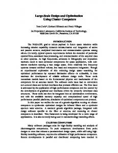
Fig. 4. Effect of collector resistance C in the small-signal model on the maximum achievable gain ( 21 ) of distributed amplifiers. Three different distributed-amplifier topologies have been compared. CC-Cascode design denotes that the active cell of each distributed amplifier stage is composed of a common-collector stage followed by a cascode pair (such as Circuit A). CC-Cascode with feedback denotes that two feedback resistors are added to the active cell (such as Circuit B). The number of distributed stages is shown next to each simulation point on the curve.
S
provide the required matching and flat gain conditions. The use of small value resistors enabled circuit design without any capacitor at the input or output transmission lines. Capacitors were only used for high-frequency grounding purposes at the base of common-base transistors T3 , T6 , and T9 in Fig. 1. Since no capacitors in the signal path were employed in the design, an improved low-frequency performance of the amplifier with a flat gain down to a low frequency of at least 50 MHz was achieved. An analysis of the circuit sensitivity on the magnitude of the collector series resistance (RC ) and base series resistance (RB ) was performed. The overall gain of various distributed amplifiers was simulated for this purpose using LIBRA. Three different distributed amplifier topologies were examined, namely, cascode, common collector followed by cascode (i.e., Circuit A), and common collector followed by cascode with additional feedback resistors (i.e., Circuit B). Each of these topologies can, of course, be used with a different number of stages. Fig. 4 shows the effect of collector termination resistance on the maximum achievable gain (S21 ) of distributed amplifiers using a variable number of stages of amplification and different topologies. As the collector resistance decreases, the gain of the amplifiers increases monotonically. The gain increase is partly due to the additional number of stages that can be used when the output losses induced by the collector resistance are decreased. Another contributing factor is the resulting improvement in transistor overall gain as the collector resistance is decreased. The common-collector stage followed by a cascode active cell (attenuation compensation stage, CC-Cascode) achieves the highest gain performance. CC-Cascode circuits with two feedback resistors in each active cell (see, e.g., Circuit B in Fig. 2) achieve marginally smaller gain characteristics, while their bandwidth is by at least 20% higher. The improved bandwidth characteristics are due to bandwidth enhancement of individual active stages as feedback is introduced. The gain of a cascode-based distributed amplifier is significantly lower than the other two topologies, especially if the collector resistance value is small. Fig. 5 shows a comparison of the maximum achievable gain (S21 ) of the above three topologies as the base series resistance (RB ) is varied. The collector resistance assumed for this study
MOHAMMADI et al.: DESIGN OPTIMIZATION AND CHARACTERIZATION OF HIGH-GAIN GaInP/GaAs HBT DISTRIBUTED AMPLIFIERS
Fig. 5. Effect of base resistance RB in the small-signal model on the maximum achievable gain (S 21 ) of distributed amplifiers. Three different distributed-amplifier topologies have been compared. CC-Cascode design denotes that the active cell of each distributed amplifier stage is composed of a common-collector stage followed by a cascode pair (such as Circuit A). CC-Cascode with feedback denotes that two feedback resistors are added to the active cell (such as Circuit B). The number of distributed stages is shown close to each simulation point on the curve.
1041
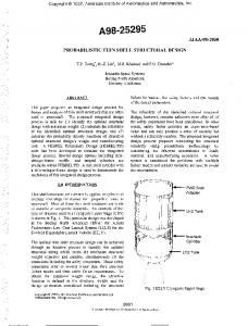
Fig. 6. Cross section of the fabricated self-aligned GaInP/GaAs HBT.
was 10 so that the effect of base resistance on the gain is best seen. A decrease in the base resistance increases the S21 gain of all the amplifiers monotonically. Gain increase is achieved by using a larger number of active stages, as well as transistors with higher gain as a result of reduced base resistance. III. GaInP/GaAs HBT MONOLITHIC-MICROWAVE INTEGRATED-CIRCUIT TECHNOLOGY The distributed amplifier of Fig. 1 (Circuit A) was fabricated using the GaInP/GaAs HBT technology developed at The University of Michigan at Ann Arbor. GaAs Technology offers the advantage of high throughput, high yield, and process maturity over its InP counterpart. This technology takes advantage of several advanced techniques that have been proven to permit realization of high-performance discrete and integrated HBT circuits of high reliability and yield [5], [6]. The HBT layers were grown using a specially developed hydride and hydrogen-free chemical beam epitaxy (CBE) process with very low defect density ( 12 dB and BW > 25 GHz. The introduction of feedback resistors in Circuit B allows one to reduce the number of stages and improve the bandwidth of the distributed amplifier by at least 20%. The effect of base and collector resistance on the overall gain of the amplifier was also considered. Based on the performed analysis, a three-stage GaInP/GaAs-based HBT distributed amplifier with a common-collector cascode active cell was designed, fabricated, and successfully tested. A gain of 12.7 dB over a bandwidth of 50 MHz–27.5 GHz was achieved. The amplifier showed very open eye-diagram characteristics and had 025-dBm sensitivity for 10-Gb/s NRZ 215 0 1 PRBS at a BER of 1009 . High-frequency noise characterization of the amplifier revealed a minimum NF of 4 dB at 3 GHz. These noise tests permitted analysis and confirmation of the sensitivity characteristics of the amplifier.
[11] [12]
[13] [14] [15]
K.W. Kobayashi, J. Cowles, L. T. Tran, A. Gutierres-Aitken, T. R. Block, A. K. Oki, and D. C. Streit, “A 50-MHz–55-GHz multidecade InP-based HBT distributed amplifier,” IEEE Microwave Guided Wave Lett., vol. 7, pp. 353–355, Oct. 1997. K. W. Kobayashi, L. T. Tran, J. C. Cowles, T. R. Block, A. K. Oki, and D. C. Streit, “Extending the bandwidth performance of heterojunction bipolar transistor-based distributed amplifiers,” IEEE Trans. Microwave Theory Tech., vol. 44, pp. 739–748, May 1996. S. Kimura, Y. Imai, Y. Umeda, and T. Enoki, “0–90 GHz InAlAs/InGaAs/InP HEMT distributed baseband amplifier IC,” Electron. Lett., vol. 31, no. 17, pp. 1430–1431, Aug. 1995. T. S. Tan, D. M. Braun, T. L. Bagwell, C. P. Kocot, J. Straznicky, and S. R. Sloan, “Flip-chip photodetector for high-speed communications instrumentation,” Hewlett-Packard J., vol. 48, pp. 102–110, Dec. 1997. J. C. Garcia, C. Dua, S. Mohammadi, and D. Pavlidis, “Hydride free chemical beam epitaxy processes and application to GaInP/GaAs HBTs,” in 38th Elect. Mater. Conf. Dig., Santa Barbara, CA, 1996, p. EE9. J. W. Park, S. Mohammadi, D. Pavlidis, C. Dua, J. L. Guyaux, and J. C. Garcia, “GaInP/GaAs HBT broad-band monolithic transimpedance amplifiers and their high-frequency small and large signal characteristics,” in IEEE MTT-S Int. Microwave Symp. Dig., vol. 1, Baltimore, MD, June 7–9, 1998, pp. 39–42. S. Mohammadi, J. W. Park, D. Pavlidis, J. L. Guyaux, and J. C. Garcia, “Optimal design and experimental characterization of high-gain GaInP/GaAs HBT distributed amplifiers,” in IEEE MTT-S Int. Microwave Symp. Dig., Anaheim, CA, June 12–19, 1999, pp. 685–688. K. W. Kobayashi, R. Esfandiari, and A. K. Oki, “A novel HBT distributed amplifier design topology based on attenuation compensation techniques,” IEEE Trans. Microwave Theory Tech., vol. 42, pp. 2583–2589, Dec. 1994. P. K. Iklainen, “Low-noise distributed amplifier with active load,” IEEE Microwave Guided Wave Lett., vol. 6, pp. 7–9, Jan. 1996. D. Pehlke and D. Pavlidis, “Evaluation of the factors determining HBT high-frequency performance by direct analysis of S -parameter data,” IEEE Trans. Microwave Theory Tech., vol. 40, pp. 2367–2373, Dec. 1992. S. Deibele and J. B. Beyer, “Attenuation compensation in distributed amplifier design,” IEEE Trans. Microwave Theory Tech., vol. 37, pp. 1425–1433, Sept. 1989. B. Agarwal, R. Pullela, Q. Lee, D. Mensa, J. Guthrie, and M. J. W. Rodwell, “80 GHz distributed amplifiers with transferred-substrate heterojunction bipolar transistors,” in IEEE MTT-S Int. Microwave Symp. Dig., Baltimore, MD, 1998, pp. 2302–2307. S. Kimura and Y. Imai, “0–40 GHz GaAs MESFET distributed baseband amplifier IC’s for high-speed optical transmission,” IEEE Trans. Microwave Theory Tech., vol. 44, pp. 2076–2082, Nov. 1996. A. B. Carlson, Communication Systems: An Introduction to Signals and Noise in Electrical Communications, 3rd ed. New York: McGraw-Hill, 1986, pp. 391–396. L. M. Lunardi, S. Chandrasekhar, A. H. Gnauck, C. A. Burrus, and R. A. Hamm, “20-Gb/s Monolithic p-i-n/HBT photoreceiver module for 1.55-�m applications,” IEEE Photon. Technol. Lett., vol. 7, pp. 1201–1203, Oct. 1995.
Saeed Mohammadi (S’90) received the B.S. degree in electrical engineering from the Iran University of Science and Technology, Tehran, Iran, in 1989, the M.S. degree in electrical and computer engineering from the University of Waterloo, Waterloo, Ont., Canada, in 1994, and is currently working toward the Ph.D. degree in electrical engineering at The University of Michigan at Ann Arbor. His research interest is in the area of high-frequency and microwave microelectronics.
1044
IEEE TRANSACTIONS ON MICROWAVE THEORY AND TECHNIQUES, VOL. 48, NO. 6, JUNE 2000
Jae-Woo Park (S’88–M’92) was born in Korea, in 1963. He received the B.S. and M.S. degrees from Kwangwoon University, Seoul, Korea, in 1987 and 1989, respectively, and is currently working toward the Ph.D. degree in electrical engineering and computer science at The University of Michigan at Ann Arbor. In 1989, he was involved in the area of material analysis at ADD, Taejon, Korea. His research interests include GaInP/GaAs HBT’s physics, process optimization, and related monolithic-microwave integrated-circuit (MMIC) design. Mr. Park was the recipient of the 1998 Judges Award presented at the IEEEMicrowave Theory and Techniques Society (IEEE MTT-S) International Microwave Symposium.
Dimitris Pavlidis (S’73–M’76–SM’83–F’93) received the B.Sc. degree in physics from the University of Patras, Patras, Greece, in 1972, and the Ph.D. degree in applied science/electronic engineering from the University of Newcastle-upon-Tyne, U.K., in 1976. In 1974, he was an Invited Guest at the Institute of Semiconductor Electronics, Technical University of Aachen, Aachen, Germany. From 1976 to 1978, he was a Post-Doctoral Fellow at the University of Newcastle-upon-Tyne, where he was engaged in microwave semiconductor devices and circuits work. In 1978, he joined the High Frequency Institute, Technical University of Darmstadt, Darmstadt, Germany, as a Lecturer, where he was involved with III–V devices and establishment of a new semiconductor technology facility. In 1980, he joined the Central Electronic Engineering Research Institute, Pilani, India, as a UNESCO Consultant. From 1980 to 1985, he was an Engineer and Manager of the GaAs MMIC Department, Thomson-CSF, Corbeville, France, where he was responsible for projects on various monolithic circuits, their technology, and process evaluation. From January to June 1983, he was a Visiting Scientist at the Centre National d’Études des Télécommunications (CNET)/France Telecom, Bagneux, France. Since 1986, he has been a Professor of electrical engineering and computer science at The University of Michigan at Ann Arbor, where he has been involved in research on heterostructure devices and materials. This includes the design, fabrication, and characterization of GaAs, InP-based HEMT’s, HBT’s, diodes for switching and mixing, and microwave/millimeter-wave monolithic heterostructure integrated circuits built with such devices. His material research covers InP and III–V nitride-based heterostructure using metalorganic chemical vapor deposition (MOCVD) and their device applications. His work in the above areas has been reported in numerous papers and reports and he holds six patents. Prof. Pavlidis was awarded the 1990 European Microwave Prize for his work in InP-based monolithic integrated HEMT amplifiers. In 1991, he received the decoration of “Palmes Académiques” in the order of Chevalier by the French Ministry of Education for his work in education. In 1992, he received the Japan Society of Promotion of Science Fellowship for Senior Scientists/Professors presented by the Japanese Government and the Humbolt Research Award for Distinguished Senior U.S. Scientists. He was the recipient of The University of Michigan at Ann Arbor 1994 Electrical Engineering and Computer Science Award and the 1996 College of Engineering Research Excellence Award.
Jean-Lous Guyaux received the B.S. degree in physics and the Ph.D. degree from the University of Namur, Namur, Belgium, in 1989 and 1995, respectively. He is currently a Member of the Technical Staff at PICOGIGA, Couraboeuf, France. Prior to joining PICOGIGA in September 1999, he was with Thomson-CSF, where he was a staff member of the Thomson-CSF Laboratoire Central de Recherches (LCR) from 1996 to 1999. His primary research areas include electronic spectroscopy and III–V growth of electronic and optoelectronic devices. He has authored or co-authored over 20 papers and holds six patents.
Jean Charles Garcia was born in Madrid, Spain, in 1960. He received the Physics degree and Bachelor’s degree in microelectronics from the National Institute of Applied Science, Toulouse, France, both in 1985, and the Ph.D. degree in microelectronic from the Centre National de la Recherche Scientifique of Sophia Antipolis, Sophia Antipolis, France, in 1988. In September 1999, he recently joined the Picogiga management staff. Prior to joining Picogiga, he was the head of the Epitaxy and Heterostructures Laboratory, which provides the epitaxial growth technology infrastructure of the Corporate Research Center, Thomson-CSF, Orsay, France. He has authored and co-authored approximately 60 papers, and ten invited papers and lectures at international conferences. He holds 15 patents. His research interests include: nitride semiconductors, GaAs/GaIn(As)P, InP/GaInAs and antimonides for optoelectronic and electronic applications, HEMT’s, HBT’s, lasers physics, growth kinetics, surface analysis, in-situ processing (etching, regrowth, selective area epitaxy), and growth of GaAs/Si, compliant substrates. He is member of various national and international scientific committees, the French Vacuum Physical Society, and the Groupe Français de Croissance Cristalline (GFCC).