International Journal of Control, Automation, and Systems Vol. 1, No. 3, September 2003
351
Design Optimization and Development of Linear Brushless Permanent Magnet Motor Myung-Jin Chung and Dae-Gab Gweon Abstract: A method of design optimization for minimization of force ripple and maximization of thrust force in a linear brushless permanent magnet motor without finite element analysis is represented. The design optimization method calculated the driving force in the function of electric and geometric parameters of a linear brushless PM motor using the sequential quadratic programming method. Using electric and geometric parameters obtained by this method, the normalized force ripple is reduced 7.7% (9.7% to 2.0%) and the thrust force is increased 12.88N (111.55N to 124.43N) compared to those not using design optimization. Keywords: Design optimization, linear brushless permanent magnet motor, positioning system.
1. INTRODUCTION The applications using high performance permanent magnet (PM) motors are increasing due to their high efficiency and power density in the area of semiconductor and precision manufacturing automation. In PM motors with salient poles, there is force ripple, which is detrimental to positioning control. This force ripple is mainly due to cogging force and mutual force ripple. In a rotary PM motor, cogging force is generated by the interaction of the rotor magnetic field with stator magnetic reluctance, and mutual force ripple is generated by the interaction of excitation current magneto-motive force with the magnetic field. In linear PM motors, there are two components of cogging force, one is the tooth ripple component, which also exists in rotary motors, and the other is the end effect component, which exists only in linear motors and is caused by the finite length of the armature. The method for minimizing the cogging force has been studied by many researchers. Among the recipes, there is skewing of the magnet [1], shifting of the magnet pole pair [2], changing the ratio of the magnet width to the pole pitch [3] and arranging the permanent magnet position without skewing [4]. These methods have been conducted using Finite Element Analysis (FEA) [5], which is generally time consum__________ Manuscript received November 15, 2002; revised April 3, 2003; accepted May 10, 2003. Myung-Jin Chung is with the Memory Research & Development Division, Hynix Semiconductor Inc., San 136-1 Amiri, Bubal-eub, Ichon, 467-701, Korea (e-mail: myungjin.
[email protected]). Dae-Gab Gweon is with the Department of Mechanical Engineering, Korea Advanced Institute of Science and Technology, 373-1 Kusung-dong, Yuson-gu, Taejon, Korea (email:
[email protected]).
ing and difficult to apply to iterative design procedures such as design optimization. Therefore, if flux density distribution is described by the electric and geometric parameters of the motor [6] and driving force, which is divided to force ripple and thrust force, is calculated by using the flux density distribution, the design optimization can be conducted by considering force ripple and thrust force as cost function and electric and geometric parameters as design variables without FEA. In this paper, we calculated the driving force, which is used for the calculation of force ripple and thrust force, in the function of electric and geometric parameters of a linear brushless PM motor (BLPMM), and used the sequential quadratic programming (SQP) method in design optimization without FEA data. Electric and geometric parameters of the linear BLPMM are selected as design variables. By design optimization, force ripple minimized and thrust force maximized linear BLPMM is developed and applied to the linear positioning system.
2. CALCULATION OF FORCE COMPONENTS Fig. 1 shows the geometrical structure of linear BLPMM, where an iron core of armature is wound with coil in three phases. The stator is attached to permanent magnets that are faced with armature wound around with N and S poles. Skewing of either the teeth or magnets is the general method to reduce the cogging force. However, skewing increases the complexity of motor construction and decreases the motor performance. Therefore, in this paper, the linear BLPMM without skewing is designed. Table 1 lists the nominal value of geometrical parameters of linear BLPMM.
International Journal of Control, Automation, and Systems Vol. 1, No. 3, September 2003
352
The end effect component is calculated at the two end sides of the armature and given by: Fe ( x0 ) = − Fe _ f ( x0 ) + Fe _ r ( x0 ) ,
Fig. 1. Geometrical structure of the linear BLPMM. Table 1. Nominal value of the geometrical parameters of the linear BLPMM. Symbol
Value
Unit
Armature length
lA
144.0
mm
Magnet width
wM
18.0
mm
Magnet pole shift length
sP
0.0
mm
Coil diameter
dco
0.4
mm
Slot depth
dS
4.0
mm
Magnet thickness
hM
2.0
mm
In the linear BLPMM, driving force consisted of cogging force and mutual force. The cogging force acting on the armature is obtained by the Maxwell stress tensor method, which integrates the no load flux density along the slot faces (tooth ripple component of cogging force) and two end sides (end effect component of cogging force) of the armature, as shown in Fig. 2. These forces acting on each surface of the armature are given by: Fc =
Le [ Bn2 − Bt2 ]dl , 2 µ0 ∫
where x0 is a relative position of stator and the armature. The tooth ripple component is calculated by summation of force acting at each slot with two sides and given by: Qs
Ft ( x0 ) = ∑ {Ftk _ f ( x0 ) − Ftk _ r ( x0 )} ,
(3)
k =1
where QS is a number of slot. The mutual force can be obtained by summation of static thrust of the each phase and given by: 3
Fm ( x0 ) = nle ∑ B p ( x0 )i p ( x0 ) ,
(4)
p =1
where n is number of coil turn, le is effective length, Bp is air gap flux density, and ip is winding coil current, respectively. The driving force can be obtained by sum of (2)-(4), and is given by: Fd ( x0 ) = Fc ( x0 ) + Fm ( x0 ) , for 0 ≤ x0 ≤ τ ,
(5)
where τ is a pole pitch. The driving force can be divided into thrust force and force ripple, where thrust force is defined as the average value of driving force and force ripple is defined as the variation from thrust force for one pole pitch, and (5) is rewritten as: Fd ( x0 ) = Fripple ( x0 ) + Fthrust ( x0 ) .
(6)
The expressions of each force component calculation are represented in Appendix A.
(1)
where Le is armature width, µ0 is magnetic permeability of air, and Bn and Bt are normal and tangential component of flux density, respectively.
Fig. 2. Cogging force components.
(2)
3. DESIGN OPTIMIZATION METHOD 3.1. Procedure of design optimization The SQP is used for design optimization of linear BLPMM. This method uses an iterative procedure, which generates a quadratic programming subproblem at each iteration, and updates the estimate, which is the Hessian of Lagrangian [7]. From (A1)-(A4), the driving force is related to the electric and geometric parameters. The parameters affecting force ripple and thrust force are selected as design variables and the other parameters are selected as fixed variables. The design variables and the range values are listed in Table 2, where the armature length is described as l A = 2nτ + ∆l for 0 ≤ ∆l ≤ τ with interger number n.
International Journal of Control, Automation, and Systems Vol. 1, No. 3, September 2003 0.16
Table 2. Range of the design variables of the linear BLPMM.
Armature length Magnet width Magnet pole shift length Coil diameter Slot depth Magnet thickness
RangeValue
Unit
lA
144.0 ~ 168.0
mm
wM
mm mm
dco
12.0 ~ 24.0 - (24.0 – wM)/2 ~ (24.0 – wM)/2 0.2 ~ 0.5
dS
2.0 ~ 4.0
mm
hM
1.0 ~ 3.0
mm
sP
wM lA sp
0.12
Normalized force ripple
Symbol
353
0.08
0.04
mm 0.00 0.0
0.2
0.4
0.6
0.8
1.0
0.8
1.0
Level of design variable
(a)
J ( x) = W1 * (max{ Fripple ( x0 ) })2 + W2 * for
1 ( Fthrust ( x0 )) 2
0 ≤ x0 ≤ τ ,
(7)
where W1 and W2 are weight functions, x denotes design variables: armature length, magnet width, magnet pole shift length, coil diameter, slot depth and magnet thickness. The fixed variables are armature width, slot pitch, pole pitch, magnet remanence flux density, air gap length and applied voltage. The constraints are maximum flux density in teeth Bmax, minimum thrust force Fthrust, temperature of coil Tcoil (see Appendix B) and maximum current flow imax. The constraint conditions are given by: g1(x)= Bmax-G1≤0,
(8)
g2(x)= G2- Fthrust≤0,
(9)
g3(x)= Tcoil -G3≤0,
(10)
g4(x)= imax –G4≤0,
(11)
200 ds dco hM
160
Thrust force (N)
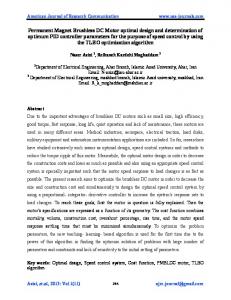
Fig. 3 shows the effect of design variables in force ripple and thrust force where design variables are divided to seven values for full range and force components are calculated by using (2)-(6). In Fig. 3 (a), magnet width has the main effect on tooth ripple component of cogging force, armature length has the main effect on end effect component of cogging force and magnet pole shift length has effect on both cogging and mutual force ripple. In Fig. 3 (b), the thrust force is increased according to the increase of coil diameter, but coil diameter is limited by current constraint. These variables have the optimum value of minimizing the force ripple and maximizing the thrust force. In this paper, cost function of design optimization procedure contains maximum force ripple and thrust force at the given design variables and is given by:
120
80
40
0 0.0
0.2
0.4
0.6
Level of design variable
(b) Fig. 3. Effect of the design variables: (a) normalized force ripple which is divided by thrust force, (b) thrust force. where G1=2.1(T), G2=125(N), G3=100( ), G4=3(A), and each constraint condition is normalized by each given value. The flux density and force components are calculated from the initial value of design variables and fixed variables. We set the initial value of the design variables as middle value of design range, and convergence tolerance as 0.01%. During the design optimization procedure, flux density, force component, and performance of linear BLPMM are calculated according to change of design variables at each iteration step. In the condition of satisfying the constraints, the design variables, which minimize the cost function, are determined. Fig. 4 shows the optimization procedure of the cost function and active constraints. Fig. 5 shows the optimization procedure of the design variables at each iteration where the slot depth is converged to maximum bound. This bound is limited by design specification.
354
International Journal of Control, Automation, and Systems Vol. 1, No. 3, September 2003
Table 3. Optimized design variables and fixed variable.
Fig. 4. Optimization procedure of the cost function and active constraints.
Armature length Magnet width Magnet pole shift length Coil diameter Slot depth Magnet thickness Pole pitch Number of pole Slot pitch Number of slot Applied voltage Number of phase Remanence flux density Armature width Air gap length
Symbol
Value
Unit
lA
160.0
mm
wM
17.76
mm
sP
- 0.25
mm
dco
0.32
mm
dS
4.0
mm
hM
2.2
mm
τ p
24.0
mm
6
-
τS Qs
8.0
mm
18
-
Vap
15
V
np
3
-
Br
1.17
T
Le
50.0
mm
δ
2.0
mm
Table 4. Characteristic values of the linear BLPMM.
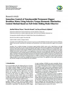
Fig. 5. Optimization procedure of the design variables. 3.2. Results of design optimization Table 3 lists the values of optimized design variables and fixed variables and Table 4 lists the characteristic values of the linear BLPMM calculated using the nominal and optimized design variables. By design optimization, the normalized force ripple is reduced 7.7% (9.7% to 2.0%) and the thrust force is increased 12.88 N (111.55 N to 124.43 N) compared to those not using design optimization. Fig. 6 shows the calculated force components, which are end effect and tooth ripple cogging force, mutual force, and driving force, of optimized linear BLPMM according to one pole pitch relative position, respectively. In Fig. 6 (a), the ratio of force ripple to thrust force is 9.7%, and the component of force ripple with the tooth ripple is 1.0%. The end effect is 8.6% and mutual force ripple is 1.6%. In Fig. 6 (b), the ratio of force ripple to thrust force is 2.0%, and the component of force ripple with the tooth ripple is
Maximum driving force Thrust force Normalized force ripple Air gap flux density Force constant Moving mass
Nominal value
Optimized value
Unit
122.41
126.93
N
111.55
124.43
N
0.097
0.020
-
0.65
0.67
T
55.77
60.46
N/A
1.57
1.65
kg
0.2%. The end effect is 1.1% and mutual force ripple is 2.1%. With this design optimization, the end effect component, which does not exist in rotary motors, is minimized by adjustment of the armature length as shown in Fig. 7 [5]. This method is proposed by Zhu [5], where Zhu used the FEA. In this paper, analytical calculation is used. Slotless armature is used to consider only the end effect cogging and the attracting force acting on each side is shown separately according to armature movement (where, F+ is attraction force of right side and F- is left side). According to ∆l, the profile of F+ is changed forward or backward from the nominal profile at l A = 2nτ and sum of each attracting force is represented with a thick line.
International Journal of Control, Automation, and Systems Vol. 1, No. 3, September 2003
355
Fig. 7 (a) shows the nominal end effect cogging force when the armature length is twice integer multiple of pole pitch. Fig. 7 (b) shows the minimum end effect cogging force obtained by selection of armature l A = 2nτ + ∆lopt + or length such as l A = 2nτ − ∆lopt − in order to minimize the end effect cogging force developed at each end side. Fig. 7 (c) shows that the end effect cogging force is maximized when armature length is l A = 2nτ + ∆lmax . The tooth ripple component is minimized by the usage of a suitable magnet width, which is the method used in rotary motor design. By shifting the magnet pole pair, the mutual force ripple and cogging force have out of phase in ripple components. The total force ripple can be reduced effectively. In this paper, cogging force (generated in the condition of no current flow) and mutual force (generated in the condition of current flow) is considered in force ripple analysis. The design optimization of linear BLPMM is conducted more effectively. 140
120
Force (N)
100 End effect cogging Tooth ripple cogging Mutual force Driving force
80
20
0
-20 0
4
8
12
16
20
24
Displacement (mm)
(a) 140
120
Force (N)
100
End effect cogging Tooth ripple cogging Mutual force Driving force
80
20
0
-20 0
4
8
12
16
20
24
Displacement (mm)
(b) Fig. 6. Calculated force components of the linear BLPMM from: (a) nominal design variables, (b) optimized design variables.
(a)
(b)
(c)
Fig. 7. End effect component of the cogging force according to armature length: (a) nominal length, (b) optimal length (c) worst length.
4. EXPERIMENTAL RESULTS The linear positioning system is constructed with design optimized linear BLPMM, air slide bearing and guide as shown in Fig. 8. The force components of designed linear BLPMM are measured at the linear positioning system. In Fig. 8, one leg of the load cell is coupled to the linear motor and the other leg is fixed to the lead screw. By changing the relative position (measured by laser interferometer of HP10706A) of armature and stator, the leg of the load cell is compressed or extended. The amount of compression or extension depends on the magnitude of applied force. The cogging force is measured without winding coil current flow. The end effect component is measured with slotless armature of the same length as designed slotted armature. The driving force is measured with cosine waveform currents flow, which is applied in each armature’s coil with phase delay of 2π/3 and 4π/3 according to position of armature, respectively. Fig. 9 shows the measured and calculated force components where tooth ripple is obtained by subtracting the end effect component from the cogging force, and mutual force ripple is obtained by subtracting the cogging force from the driving force. From Fig. 9, measured force components are very similar to the calculated values, where force ripple is increased 4% (by air and wire cable tension) and thrust force is reduced 1.8% (by wire cable resistance) compared with the calculated value. The maximum difference in measured driving force is 2.8% of the calculated value.
5. CONCLUSIONS The analytic model representing the driving force in the function of electric and geometric parameters
International Journal of Control, Automation, and Systems Vol. 1, No. 3, September 2003
356
APPENDIX A In the force calculation equations, the flux density distribution obtained from magnetic field analysis is used and given by B( x) = α s
∞
∑
n =1,3,5,..
β s (e
2 nπ hM τp
e
nπδ τp
+e
−
nπδ τp
) cos
nπ x , τp (A1)
α s = − f ( µ M , δ , hM ) β s = f ( Br , α , δ ,τ p , µ M , µ0 , hM )
where
Fig. 8. Linear positioning system developed with linear BLPMM. 140
for
(k − 1)τ S − ws / 2 ≤ x ≤ (k − 1)τ S + ws / 2 in k=1, 2, 3 … QS and µM is magnetic permeability of PM, δ is air gap length, hM is magnet height, Br is remanence flux density of magnet, α is ratio of magnet length to pole pitch, τp is pole pitch, and wS is slot width, respectively. Each force component is calculated using the flux density distribution. The cogging force acting on armature of linear BLPMM as shown in Fig. 2 is obtained by the Maxwell stress tensor method and mutual force is obtained by the Lorentz force equation. The tooth ripple component is calculated by summation of force acting at each slot with two sides and given by Qs
120
Ft ( x0 ) = ∑ {Ftk _ f ( x0 ) − Ftk _ r ( x0 )} k =1
100
Force (N)
and
End effect cogging Tooth ripple cogging Mutual force Driving force
80
20
0
-20 0
4
8
12
16
20
24
Displacement (mm)
Fig. 9. Measured force components of optimized linear BLPMM. of linear BLPMM is developed. The design optimization is conducted by means of considering force ripple and thrust force as cost function and electric and geometric parameters as design variables without FEA. By design optimization, the normalized force ripple is reduced 7.7% (9.7% to 2.0%) and thrust force is increased 12.88N (111.55N to 124.43N) compared to those not using design optimization. Designed linear BLPMM is developed and applied to linear positioning system. For further reduction of force ripple control strategies such as current shaping or force estimator and observer are needed in control methods.
le Qs = ∑ 2 µ 0 k =1 −
x0 + ( k −1)τ s + wS
2 ( ) B x dx ∫ w S x0 + ( k −1)τ s + 2 3 wS x0 + ( k −1)τ s + 2 2 ( ) B x dx ∫ x0 + ( k −1)τ s + wS
(A2)
The end-effect ripple component is calculated at the two end sides of armature and given by: Fe ( x0 ) = − Fe _ f ( x0 ) + Fe _ r ( x0 ) x0 −∆l 2 − B ( x ) dx ∫ , l x0 −( hA +∆ ) = e + +∆+ τ x Q h A 2µ0 0 s s 2 B ( x)dx + ∫ x0 +Qsτ s +∆l
(A3)
where hA is armature height. The mutual force can be obtained by summation of static thrust of each phase and given by
International Journal of Control, Automation, and Systems Vol. 1, No. 3, September 2003 3
Fdrv ( x0 ) = nle ∑ B p i p p =1 3
= nle ∑
p =1
τ τ x0 + s + ( p −1)τ s + s 4 2
∫
τ x0 + s + ( p −1)τ s 4
(A4) B( x) J c ( x)dx,
[4]
where Jc is current density distribution.
APPENDIX B The source of heat is current that flows through the coil with resistance. The heat dissipation occurs by convection, conduction or both. The heat dissipation model of the linear BLPMM is presented in Fig. A1. Four paths divide the path of heat transfer as shown in Fig. A1 (a). In the heat dissipation model, temperature gradation in the coil area is assumed to not exist. The heat generated from the coil is given by qs = i 2 R ,
+
Tc − Ta T − Ta + c R31 + R32 R41 + R42
[5]
[6]
(A5)
and total heat dissipated through each heat transfer path is given by T − Ta T − Ta ∆T = c + c qd = ∑ Rth R11 R21 + R22
[3]
[7] [8]
(A6)
where ∆T is a temperature difference between air and 2 coil, ∑Rth is a total thermal resistances, R11 = , hτ s Le
π (2d s + τ s ) 2 , , R22 = R32 = 16kb d s Le hτ s Le 2( H − d s ) 1 is a thermal resisR41 = , R42 = hτ s Le kbτ s Le tance of the each heat transfer path shown in Fig. A1 (b) and H is a thickness of iron core. The convection coefficient of air h is 4.5W/m2℃ and conduction coefficient of iron core kb is 54 W/m℃, respectively [8]. From Eq. (A5) and (A6), the temperature of coil is obtained by identfying generated heat and dissipated heat. R21 = R31 =
REFERENCES [1] G.-H. Jang, J.-W. Yoon, K.-C. Ro, N.-Y. Park, and S.-M. Jang, “Performance of a brushless DC motor due to the axial geometry of the permanent magnet,” IEEE Trans. on Magnetics, vol. 33, no. 5, pp. 4101-4103, September 1997. [2] I.-S. Jung, S.-B. Yoon, J.-H. Shim, and D.-S. Hyun, “Analysis of forces in a short primary
357
type and a short secondary type permanent magnet linear synchronous motor,” IEEE Trans. on Energy Conversion, vol. 14, no. 4, pp. 12651270, December 1999. K. Touzhu Li and G. Slemon, “Reduction of cogging torque in permanent magnet motors,” IEEE Trans. on Magnetics, vol. 24, no. 6, pp. 2901-2903, November 1988. T. Yoshimura, H. J. Kim, M. Watada, S. Torii, and D. Ebihara, “Analysis of the reduction of detent force in a permanent magnet linear synchronous motor,” IEEE Trans. on Magnetics, vol. 31, no. 6, pp. 3728-3730, November 1995. Z. Q. Zhu, Z. P. Xia, D. Howe, and P. H. Mellor, “Reduction of cogging force in slotless linear permanent magnet motors,” IEE Proc.-Electric Power Application, vol. 144, no. 4, pp. 277-282, 1997. M.-J. Chung and D.-G. Gweon, “Modeling of the armature slotting effect in the magnetic field distribution of a linear permanent magnet motor,” Electrical Engineering, vol. 84, no. 2, pp. 101-108, 2002. A. Grace, Optimization Toolbox User’s Guide. The Math Works Inc., 1990. J. P. Holman, Heat Transfer. MaGrawHill Inc., 1981.
Myung-Jin Chung received the B.S. degree in Mechanical Engineering from Hanyang University in 1989, the M.S. degree in Production Engineering from KAIST in 1991, and the Ph.D. degree in Mechanical Engineering from KAIST in 2002. His interests include linear motor, high precision positioning system, and semiconductor manufacturing system.
Dae-Gab Gweon received the B.S. degree in Mechanical Engineering from Hanyang University in 1975, the M.S. degree in Mechanical Engineering from KAIST in 1977, and the Ph.D. degree in Mechanical Engineering from Stuttgart University in 1987. His interests include high precision positioning system and high precision measurement system.