Dec 14, 2015 - abroad, or from public or private research centers. L'archive ouverte ... the management software and coupling it with appropriate sensors and ...
Designing Autonomic Management Systems by using Reactive Control Techniques ´ Nicolas Berthier, Eric Rutten, No¨el De Palma, Soguy Mak-Kar´e Gueye
To cite this version: ´ Rutten, No¨el De Palma, Soguy Mak-Kar´e Gueye. Designing Autonomic Nicolas Berthier, Eric Management Systems by using Reactive Control Techniques. IEEE Transactions on Software Engineering, Institute of Electrical and Electronics Engineers, 2015, pp.18.
HAL Id: hal-01242853 https://hal.inria.fr/hal-01242853 Submitted on 14 Dec 2015
HAL is a multi-disciplinary open access archive for the deposit and dissemination of scientific research documents, whether they are published or not. The documents may come from teaching and research institutions in France or abroad, or from public or private research centers.
L’archive ouverte pluridisciplinaire HAL, est destin´ee au d´epˆot et `a la diffusion de documents scientifiques de niveau recherche, publi´es ou non, ´emanant des ´etablissements d’enseignement et de recherche fran¸cais ou ´etrangers, des laboratoires publics ou priv´es.
AUTHORS’ VERSION
1
Designing Autonomic Management Systems by using Reactive Control Techniques ´ ¨ De Palma, Soguy Mak-Kare´ Gueye Nicolas Berthier, Eric Rutten, Noel Abstract—The ever growing complexity of software systems has led to the emergence of automated solutions for their management. The software assigned to this work is usually called an Autonomic Management System (AMS). It is ordinarily designed as a composition of several managers, which are pieces of software evaluating the dynamics of the system under management through measurements (e.g., workload, memory usage), taking decisions, and acting upon it so that it stays in a set of acceptable operating states. However, careless combination of managers may lead to inconsistencies in the taken decisions, and classical approaches dealing with these coordination problems often rely on intricate and ad hoc solutions. To tackle this problem, we take a global view and underscore that AMSs are intrinsically reactive, as they react to flows of monitoring data by emitting flows of reconfiguration actions. Therefore we propose a new approach for the design of AMSs, based on synchronous programming and discrete controller synthesis techniques. They provide us with high-level languages for modeling the system to manage, as well as means for statically guaranteeing the absence of logical coordination problems. Hence, they suit our main contribution, which is to obtain guarantees at design time about the absence of logical inconsistencies in the taken decisions. We detail our approach, illustrate it by designing an AMS for a realistic multi-tier application, and evaluate its practicality with an implementation. Index Terms—Autonomic computing, Coordination, Discrete control, Reactive programming
F
1
I NTRODUCTION
T
HE
ever growing complexity of computer systems and applications has led to the construction of physical and virtual facilities that are hard to manage by humans without automated assistance. Autonomic Management Systems (AMSs) [1] represent an attempt to tackle this problem. Their goal is to ensure performance and availability of a managed system in an automated manner. To this end, and as illustrated in Fig. 1, AMSs can be designed as a (composition of one or more) feedback loops: they monitor the status of the resources constituting the system under management through “sensors”, and react to certain events such as failures or overloads by acting upon it through “actuators”. Designing an AMS to manage a system roughly consists in conceiving the management software and coupling it with appropriate sensors and actuators. 1.1
Designing Autonomic Management Systems
The core constituents of management softwares are autonomic managers. Each manager usually deals with a particular aspect of the management task (e.g., repairing failures, allocating resources or switching an algorithm to some degraded mode when the system is overloaded). They handle measures and events from sensors (e.g., watching heartbeats • • •
Nicolas Berthier, No¨el De Palma and Soguy Mak-Kar´e Gueye are with the ERODS team, University of Grenoble, LIG Bˆat. C, 220 rue de la Chimie, 38 400 St Martin d’H`eres, France. Nicolas Berthier is also with the SUMO team, INRIA Rennes - Bretagne Atlantique, Campus de Beaulieu, 35 042 Rennes Cedex, France. ´ Eric Rutten is with LIG/INRIA Grenoble - Rhˆone-Alpes, Inovall´ee, 655 av. de l’Europe, Montbonnot, 38 334 St Ismier, France.
Management Software Flow of Flow of Monitored Data Execution Orders Actuators
Sensors
Managed System Fig. 1. Autonomic management system as feedback loop.
to detect failures, receiving load measurements, monitoring network links), take management decisions aiming for maintaining the managed system in a set of operating states that are considered “safe” or “desirable” (e.g., servicing requests quickly enough, not overloaded, sufficiently replicated), and act upon it accordingly by emitting commands. We denote by decision logic the behavior of a manager in terms of the actions it performs on the managed system under certain operating conditions. Huebscher and McCann [2] survey available solutions for specifying the decision logic of autonomic managers: it is usually described using components encapsulating sequential code and memory, e.g., in Fractal [3], and may also involve a set of eventcondition-action (ECA) policies [4] or similar rules [5] fed to a (potentially resource-intensive) run-time solver; machine learning or satisfiability [6] techniques may also be involved. In most cases, the decision logic is expressed in terms of events, measures, and an architectural model, the latter embodying the necessary knowledge about the various constituents of the managed system. The latter can be considered as a composition of managed entities (MEs), such as computing resources or the multiple modes of an
2
AUTHORS’ VERSION
algorithm. The portions of code taking decisions may execute in a centralized manner, on a physical or virtual machine committed to the management of all entities involved; alternatively, they can be distributed and execute on the managed machines themselves. When multiple management aspects are considered, several managers are combined to constitute the whole decision logic of the AMS software. They may execute concurrently, or be combined in a hierarchical way so as to handle managed entities considered more or less abstractly. 1.2
Coordination Needs
However, making autonomic managers cooperate to avoid incoherent decisions is a challenging problem [7] that still draws significant attention from the autonomic systems research community (we review state-of-the-art solutions in Section 10): Entity-level Coordination Problem. Indeed, autonomic managers that do not cooperate may take incompatible decisions about the same ME (e.g., repairing a machine and deciding to release one at the same time). If the managers are separate components, making them cooperate often requires adding intricate glue code and is tedious and error-prone. In the case of rule-based managers pertained to a common subset of actions, their combination requires at least defining policies for handling conflicting rules (i.e., that do not agree on actions given the same operating conditions). Global Consistency Issue. Further, several managers handling distinct MEs may also take decisions having counterproductive effects, as events occurring on one particular entity may have remote impacts on others (e.g., due to workload dependencies). In such cases, determining appropriate management operations requires taking some knowledge about the state of other MEs into account. We illustrate this problem in Section 3.3. 1.3
Summary of the Contribution
In this article, we address the above coordination problems by putting forward a new methodology for the design of AMSs founded on techniques usually employed for designing reactive control systems [8]. Indeed, such techniques allow the control of entities that are subject to competing dynamics, e.g., due to physical laws. They provide: (i) high-level languages for the specification of controlled systems (e.g., by means of automata); (ii) efficient verification techniques for design-time validation (e.g., model-checking); (iii) means for property enforcement (e.g., discrete controller synthesis to impose invariants on programs, by automatic generation of maximally permissive controllers ensuring some given properties). In former works, we [9, 10, 11] used such techniques to augment an AMS composed of legacy managers with an ad hoc reactive controller component so as to inhibit managers’ executions when necessary; the controller was built based on a reactive model of existing manager components. By contrast, we extend this previous work by leveraging the modeling capabilities of high-level reactive languages to model the managed entities as well as specify the management strategies. In other words, in our previous works the
reactive controller was only used to inhibit the execution of already existing manager components that needed to be modeled manually, whereas in our new contribution the parts of the manager components that take management decisions are removed and it is a reactive program that takes those decisions. Indeed, a model of each ME and associated autonomic management strategies are specified by means of reactive programs, and discrete controller synthesis is used to statically enforce logical coordination policies and obtain an object, say DL, encoding the full decision logic of the AMS. This design technique allows to obtain guarantees on the run-time behavior of the resulting combination of management strategies at design time. In our case, the consistency of several management decisions is statically guaranteed by imposing logical coordination policies expressed in a declarative way. Also, compiled and combined with appropriate pieces of software driving (legacy) sensors and actuators, DL makes up an AMS software that is very lightweight compared to existing solutions for specifying the decision logic mentioned in Section 1.1, that rely on run-time solvers or other kinds of intricate computations. Using this technique, we address both: (i) entity-level logical coordination problems; and (ii) conflicts arising when one management strategy leads to decisions that would not have been taken if some global knowledge about the other MEs and intrinsic effects of said decisions on remote MEs was available. In this sense, our solution prevents the designer of the AMS software to manually implement, maintain, and interpret a registry of “global knowledge” about the managed system: only some “local knowledge” must be provided by each model of ME w.r.t. the desired system management goals. Our approach is complementary to other control approaches based on differential equations, for which classical control theory provides methods for the design of wellcoordinated control loops. For such controllers we offer high-level programming support for their safe implementation. For the more logical state and events aspects of the considered systems, we additionally offer tool support for the design of discrete controllers. We illustrate and exemplify our proposal by focusing on the management of replication-based multi-tier applications, and evaluate its practicality with a proof-of-concept implementation. Although the resulting software currently involves a centralized computing component (hence preventing the AMS software itself from being fault-tolerant), and imposes some modeling of the managed system a priori, we claim our method is a first and significant step toward robust and reliable AMSs whose behavioral correctness can be statically guaranteed. 1.4
Outline of the Article
The remaining of the article is organized as follows: We first give in Section 2 some background on reactive control techniques, as well as associated notations necessary to comprehend our contribution. In Section 3, we introduce a realistic running example that we use to illustrate and evaluate our contribution. Section 4 presents an overview of the proposal, further detailed in subsequent Sections 5, 6
BERTHIER et al.
3
i
Bit
c0
Bit’
c
TwoBits Fig. 2. Data-flow representation of the parallel composition TwoBits of two communicating nodes Bit and Bit’.
0
i Bit
0
c0 Bit’
and 7. We describe our implementation of the example and validate the correctness of its behavior in Section 8, and discuss current limitations and further extensions in Section 9. Finally, Sections 10 and 11 review related works and conclude.
2
R EACTIVE C ONTROL S YSTEMS D ESIGN
Let us now detail the background on reactive design techniques that is required to understand the design approach we put forward in this article. Although many solutions exist for the design of reactive control systems [8], in this Section we mainly focus on the synchronous paradigm as it constitutes the core of our approach. We first detail the latter programming technique, and then turn to discrete controller synthesis principles. 2.1
Synchronous Programming
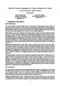
Constructing a reactive control system according to the synchronous paradigm [12] consists in programming an infinite loop that perpetually gathers data (e.g., using sensors), computes decisions, and then acts upon the system (e.g., through actuators). Synchronous languages help designing the computational part of the loop by assuming that the computations are performed in zero time (this is called the synchrony hypothesis); decisions are then considered to be taken atomically at discrete instants in time. Existing synchronous languages notably comprise declarative data-flow solutions such as L USTRE [13] and S IGNAL [14]. They are formally-defined, and come with a variety of efficient techniques and tools for statically verifying properties by model-checking, or performing automated tests [12, 15]. These academic languages and tools have led to the development of industrial-scale toolsets such as SCADE, that has been successfully used for designing safety-critical systems [16]. Synchronous programs may be compiled into a statically scheduled piece of efficient sequential code (cf. Section 2.1.2 below), as well as distributed tasks executing with some operating system support [17]. Main Concepts. The basic blocks used for building synchronous programs are nodes. A node has an implicit basic clock describing the discrete instants at which it evolves and computes output signals based on input signals. Nodes having the same basic clock are considered as evolving simultaneously. We call input vector (resp. output vector) a valuation of all input signals (resp. output signals) of a synchronous program. Example of Synchronous Data-flow Node. We depict in Fig. 2 the data-flow representation of an example synchronous node TwoBits based on two inner instances of the same node Bit and Bit’. It has one input signal i (for “increment”) and one output signal c (for “carry”). Having the same implicit basic clock as TwoBits, both inner nodes
i i/c
0
c0 c0 /c
1
i
00
i
i
01
i/c 1
c0
i
i i
11
i
10
i
TwoBits=Bit×Bit’
Fig. 3. Two Boolean Mealy automata Bit and Bit’ synchronized via a signal c0 , and the product TwoBits of their parallel composition.
are synchronized, yet communicate through the signal c0 : they can be seen as communicating instantaneously. Data-flow Notations. In the sequel of the article, and except in automata where they describe transitions, simple arrows ( ) depict signals such as i, c or c0 in Fig. 2, and double arrows ( ) represent sets of such signals. In all figures, and denote general information flows, such as data assignments or events (interrupts, callbacks), that are not signals in the synchronous programming sense; is a call to a method. Boxes represent synchronous nodes. 2.1.1
Synchronous Nodes as Boolean Mealy Automata
As explained by Maraninchi and R´emond [18], the behavior of synchronous nodes such as Bit or TwoBits can be described with Boolean Mealy Automata (BMAs); the authors also formally define composition operators on BMAs. Notably, the parallel composition is essentially a synchronous product. Communication is based on the asymmetric synchronous broadcast mechanism, much similar to signal transmissions in synchronous hardware circuits. BMAs build up on classical Mealy automata: guards of transitions are Boolean formulas on input signals, and output signals can be emitted when a transition is fired. Other than being deterministic, a BMA must be reactive to represent an executable synchronous node: i.e., for each valuation of its inputs, at least one guard must hold among those associated with the transitions leaving a state. Automata Notations. In the sequel of the article, we use the following syntax for transition labels: “i ∨ j/o, p” where i ∨ j is an example guard built from the set of input signals, o and p are example output signals. Also, if a state does not satisfy the reactivity condition, then an implicit self-loop emitting no output is assumed. Refining the example of Fig. 2, we depict in Fig. 3 an example parallel composition of BMAs (each BMA on the left corresponds to an inner node of Fig. 2). The automaton Bit (resp. Bit’) reads i (resp. c0 ) at each instant where the nodes evolve, and raises c0 (resp. c) every two instants where i (resp. c0 ) holds. The result of their composition is a two bits counter, i.e., the automaton TwoBits, that reads the signal i and raises c every four i’s. Note that emitting c0 in Bit, and reacting to c0 in Bit’, are combined into a single transition, making communication instantaneous. BMAs with Integer I/Os. In the sequel, we shall describe synchronous nodes involving integer inputs and outputs, plus arithmetic conditions. Note however that such models remain finite-state systems, as no integer memory will be necessary to represent their state.
4
AUTHORS’ VERSION
2.1.2 Result of Synchronous Program Compilation A synchronous program can be translated into a piece of efficient sequential code. We call tick the resulting object, encapsulating: • • •
some memory representing the state of the program; a reset() method, resetting the tick to its initial state; a step(I) method to be used to execute one reaction of the system, given the input vector I. One call to the step() method updates its internal state, and produces an output vector.
In terms of BMAs, and considering a tick object resulting from the compilation of the parallel composition of several automata, one call to tick.step(I) behaves as the triggering of one transition of their product, although this product is never actually computed. For instance, the program depicted on the left of Fig. 3 translates into a tick object encapsulating two internal Boolean state variables, say x and y , and whose step() method takes the value of i as argument and computes c and new values x0 and y 0 for its state variables, with sequential code whose form is very close to the following system of four equations: � 0 x = (x ∧ i) ∨ (x ∧ i) c0 = x ∧ i ← Bit 0 0 y = (y ∧ c ) ∨ (y ∧ c0 ) c = y ∧ c0 ← Bit’
with x ∧ y initially holding. From this tick in its initial state, n successive calls to its step() method with a sequence of inputs i1 , . . . in is equivalent to “executing” the automaton TwoBits of Fig. 3 with i = it at each instant t; the resulting sequence of outputs represents the successive valuations of c. 2.1.3 Executing Synchronous Programs Once the tick has been produced, one eventually has to integrate it into an execution platform. Doing so involves using some integration code, whose main goal is to trigger the execution of tick.step() at the relevant instants, feeding it with the appropriate input vector, and dealing with the output vector. In environments allowing concurrent executions, the integration code must also ensure that there is at most one non-terminated call to a method of the tick at a time. Synchronous Program Interface. First of all, the origins and semantics of the signals input and output by a synchronous program impact the expected behavior of its integration code. Input signals of synchronous programs can be distinguished into two categories: •
•
Measures (also referred to as continuous inputs) always have a meaningful value, whenever they are retrieved or measured; Impulses are similar to event notifications; they can be said as either present or absent1 .
Output signals of a program most often consist in commands to be sent to actuators, plus monitoring data. Structure of the Integration Code. Fig. 4 depicts the structure of the integration code in charge of executing a given tick. I is the input vector of the tick.step() method, and O is 1. Note that synchronous languages provide means to make such inputs carry typed values whenever they are present.
step() Impulses Measures
I
tick
O
Actions
Fig. 4. Integration code representation. Dashed areas depict the core pieces of integration code.
its result. The two dashed areas represent the core pieces of integration code. The decision code (on the left) is in charge of deciding when to call the tick.step() method, and building I. Continuous inputs are sampled when needed (typically, when the decision to execute the tick has been taken). Being intrinsically sporadic, impulse inputs are serialized upon arrival into a dedicated input queue, whose contents are used by the decision code. The remaining piece of integration code (on the right) always executes when the call to tick.step() terminates. Its role is to translate the resulting output vector O into appropriate commands to the actuators. Triggering Mechanism. Obviously, some sort of event must trigger the execution of the decision code. For instance, it may be an external notification sent when the input queue becomes non-empty, a timer expiration event, or simply the end of the previous reaction. Once the decision code executes, it scans the contents of the input queue. Based on this information, plus possibly some measures of continuous inputs, it can decide to build an input vector and execute the tick.step() method. Deciding Relevant Instants. Several policies exist to decide when to build an input vector and execute the tick, based on the contents of the input queue; Caspi and Girault [19] put forward the program input language (without formally specifying it), that defines triggering policies based on this contents only. For instance, in the case of periodic executions of the tick, the program input language specifies that a reaction takes place as soon as the queue of impulse inputs contains a timer expiration notification (that manifests to the program as its basic clock only, not as a value in its input vector); note that in this case, it may be relevant to build input vectors full of absent values. Another policy consists in triggering a reaction as soon as the input queue becomes non-empty, and the last call to tick.step() has terminated. 2.2
Discrete Controller Synthesis
The principle of Discrete Controller Synthesis (DCS) has been proposed by Ramadge and Wonham [20] in the framework of language theory. It has later been extended to form a set of constructive techniques used for designing discrete event dynamic systems. The principle of DCS for safety can be explained in computational terms. Let B a set of behaviors (e.g., BMAs) with disjoint sets of input and output signals I and O, plus an invariant predicate ϕ expressed in terms of a formula involving signals belonging to I ∪ O. Let also Ic ⊆ I be a set of controllable inputs. A DCS algorithm for safety computes a controller C outputting the signals of Ic , such that the
BERTHIER et al.
behavior resulting from the parallel product of the B ’s and C satisfies the invariant ϕ; the set of inputs of the resulting system is I \ Ic . The controllable inputs express the set of “levers” given to the synthesized controller so that it can restrict the behaviors B to enforce the invariant ϕ. Note also that C may not exist, meaning that the controllable inputs do not provide sufficient means to avoid violations of the invariant (or that ϕ is unsatisfiable). On the Maximal Permissivity of the Controller. Observe that DCS algorithms for safety produce controllers that are maximally permissive, meaning that they only enforce unreachability of states violating the specified invariants. In practice, the resulting behavior is also usually less restrained than the one that could be obtained when programming the solution manually (e.g., by involving additional communications between the B ’s to implement synchronizations — means that can be very tedious when the behaviors involved are complex or numerous). One consequence of the maximal permissivity of the controller is that non-progressing controlled behaviors (e.g., that do not traverse transitions they are expected to) reveal that the enforced invariant is intrinsically incompatible with the given set of behaviors. These incompatibilities can be avoided by enforcing reachability objectives in addition to safety. One can also verify liveness properties on the controlled behavior using model-checking, or enforce bounded liveness properties (stating that some predicate holds before some fixed period of time), that are also safety properties. Existing DCS Tools for Synchronous Languages. Marchand et al. [21] developed the S IGALI tool for the synchronous language S IGNAL [14]. Heptagon/BZR [22, 23] extends a dataflow language similar to L USTRE [13] with new behavioral contracts by integrating S IGALI as a compilation phase. Although the models and properties involved in our design can be handled by S IGALI, it is worth noting that Berthier and Marchand [24] recently proposed the new DCS tool ReaX, that allows to take quantitative aspects into account.
3
R UNNING E XAMPLE
To illustrate and exemplify our proposal, without loss of generality, we mainly focus on the case of replication-based multi-tier applications, i.e., distributed software systems handling input requests from external stakeholders such as replicated server systems. These distributed computing systems involve several tiers, each of which is in charge of providing a specific service, e.g., database management or web page generation, by using services provided by other tiers. Such services may further be replicated on several nodes (i.e., physical or virtual machines) for performance and availability purposes. A load balancer executes on each tier directly requesting services from a replicated tier; its roles are to balance the workload between the replicated nodes, and ensure fail-over. 3.1
Example Replication-based 4-tier Application
Our example application is a web-server setup comprising an Apache server handling HTTP requests, a Tomcat service dealing with dynamic content and accessing a Mysql
5
database through a MysqlProxy service. The service dependency chain is then: Apache → Tomcat → MysqlProxy → Mysql where “→” shows the direction of service requests. For isolation and performance purposes, each service of the application is mapped onto its respective tier: Tapache → Ttomcat → Tmysql-proxy → Tmysql Furthermore, Tomcat and Mysql are considered performance-critical services, meaning that they need to be replicated for performance purpose. Hence, tiers Ttomcat and Tmysql may encompass multiple nodes hosting the associated service, the number of which can be determined dynamically based on workloads. As a consequence, tiers Tapache and Tmysql-proxy ought to act as load balancers. Required Management Needs. To fulfill performance and availability requirements while minimizing resource consumption, such an application mapping calls for some management tasks to be performed. For instance, the number of nodes constituting replicated tiers (such as Ttomcat and Tmysql ) must be determined somehow; software or hardware failures occurring on any node must also be detected and repaired when necessary. 3.2
Example Autonomic Managers
Based on the above management needs, we propose to use two self-repair and self-scaling classical autonomic managers to handle the various tiers of our example application (hence, we consider each tier as an individual ME): The role of a self-repair manager is to enforce a certain degree of redundancy so as to tolerate up to a certain number of failures among the machines allocated to the managed system. Thus, this manager handles failure detection notifications provided by dedicated sensors (e.g., through heartbeats). Once a failure is detected, it tries to replace the failed machine. Management operations to be performed upon replacement include the deployment (start up, configuration) of the services that were running on the aforementioned machine. Besides, the objective assigned to a self-scaling manager is to sustain some performance or wealth measures (e.g., mean CPU utilization, memory usage) in particular “safe ranges” by dynamically adapting the number of nodes allocated to a replicated service. All tiers of our example application mapping need to be handled using a self-repair manager. Alternatively, a selfscaling manager is only required for both Ttomcat and Tmysql tiers. 3.3
Illustrating Global Consistency Issues
Let us now use our example to further illustrate global consistency issues mentioned in Section 1.2. The failure of a node in Ttomcat may automatically lead to: (i) a temporary overload in the remaining nodes of Ttomcat while the failed node is being replaced due to a decision imposed by a selfrepair manager; (ii) the possible rejection of requests that cannot be handled due to this overload, therefore a decrease in the workload at Tmysql-proxy and Tmysql ; (iii) an underload in Tmysql until Ttomcat recovers its initial working state. As a consequence of this series of events, an uncoordinated selfscaling manager may lead to a shut-down (or release) of
6
AUTHORS’ VERSION
a supernumerary node of Tmysql . Once the tier Ttomcat has recovered its initial number of nodes, the workload arriving at Tmysql-proxy and Tmysql increases up to its initial level, leading to a new adjustment of the number of machines of Tmysql . In the end, Tmysql has unnecessarily undergone two management operations. This example stresses the need to take the remote impacts of events occurring on particular MEs on others into account in order to manage the whole system consistently. The main contribution of our work is indeed to provide a solution for statically guaranteeing the absence of such intricate consistency issues.
4
OVERVIEW AND A RCHITECTURE OF THE P RO -
Inter-tier
Tier-level
Î Coordination
4.1
Design Principles
The main point of our proposal is to gather behavioral models of each ME into a global synchronous program. This technique allows the expression of (i) autonomic management decisions, as well as (ii) coordination policies. Independent autonomic management directors determine management decisions in function of information provided by the behavioral models of the MEs. Directors are easily expressible (e.g., in a declarative way) as systems of equations, and are programmed as synchronous nodes; they exhibit some means to influence their decisions. Coordination policies are independent from the directors, and are predicates modeling all admissible behaviors of the managed system (possibly expressed by complementing all non-admissible behaviors). DCS techniques are then used to synthesize a controller restricting management decisions taken by the directors so as to enforce the coordination policies. The resulting synchronous program is compiled into a single piece of sequential code as explained in Section 2.1.2, and can be both simulated or combined with appropriate pieces of sequential software driving sensors and actuators (called operating code — see below) to build up the complete AMS software. 4.2
Architecture of the Coordinated AMS
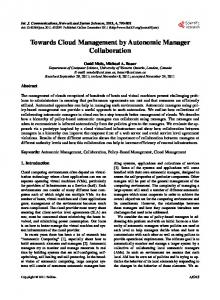
We illustrate in Fig. 5 the overall structure of the synchronous AMS in the case of multi-tier applications. From bottom to top: each Ê tier is considered as an ME, encapsulating a set of machines (nodes) dedicated to run a particular service; they are ordered according to the workflow: external requests are received by tier T1 , and a tier Ti uses services provided by tier Ti+1 . A tier Ti is managed through a tier driver consisting of some Ë operating code acting upon and monitoring the tier, coupled with a
IP→n
TP1
TP2
TPn
do,1
do,2
do,n
d2,1
d2,2
d2,n
d1,1
d1,2
d1,n
M1
M2
Mn
T1
T2
Tn
Independent Autonomic
Í Management Directors
Ì
Behavioral Models
Ë
Operating Code
Ê
Tiers
POSAL
We claim that, as an autonomic management software is a typical reactive control system, its development would greatly benefit from design techniques usually employed in this domain. We first give an overview of our proposal for designing such software with synchronous languages by focusing on the architecture we obtain in the case of multitier applications. It is made up of several conceptual layers, each detailed in turn in subsequent sections.
IP→2
Ï Coordination
Fig. 5. Principle of the approach for the management of an n-tier application. “ ” represent service requests. Dotted areas depict synchronous nodes encoding predicates. A dashed area encompassing tier-level coordination predicate TPi also covers the directors it controls. Plain areas represent synchronous nodes controlled by a synthesized coordination controller. Most synchronous signals have been omitted to ease readability.
Ì behavioral model Mi which is typically an automaton. The former part essentially consists in pieces of sequential code that execute asynchronously in response to signals output by the latter. For instance, the Ttomcat tier of the example depicted in Section 3.1 can be represented as an instance of the behavioral model of a replicated tier (say, Mtomcat ); its associated pieces of operating code handle the nodes of this tier only. A series of Í independent autonomic management directors d*,i are responsible for implementing management strategies for each tier Ti , by using information from, and issuing requests to, its associated behavioral model Mi . Here, aforesaid information and requests are synchronous signals as depicted in Section 2.1. The directors are said independent in the sense that they are designed independently from each other: they are self-contained and encapsulate every signal computation and potential memory variables, if any, required for them to take their decisions. Considering the Ttomcat tier in our example, a synchronous node drepair,tomcat (resp. dscaling,tomcat ) encodes the repair (resp. scaling) decision logic; in the case of the non-replicated Tapache tier, only an drepair,apache instance shall be used. Coordination policies are enforced by specifying invariant predicates. A set of predicates TPi ensures Î tier-level coordination by restraining the behaviors of the directors of a single tier Ti . Ï Inter-tier coordination predicates IP→i+1 further restrain the behaviors of the directors of tier Ti+1 : they control management decisions that need to be consistent with the status of tiers T1 to Ti , i.e., tiers whose operating state can remotely impact tier Ti+1 .
BERTHIER et al.
4.3
7
Concrete Result
In the next section, we show a way of coupling behavioral models written as synchronous programs with associated operating code, by detailing the structure of the drivers for managed entities we propose. Sections 6 and 7 demonstrate the use of the resulting drivers in order to develop consistent AMSs, by specifying management strategies and coordination policies for them.
Command Part n
5.1
Overall Architecture of ME Drivers
We depict the interactions of the two main parts of an ME driver in Fig. 6. The design of such a driver is inspired by the usual distinction between command and operative parts customary in the field of synchronous circuits development, where a control part outputs signals commanding another portion of circuit that operates on data and notifies statusrelated information. One ME driver is thus made up of a command part and an operative part. 5.2
Acting and Sensing: Operative Part
Ë
An ME driver first comprises a set of pieces of sequential operating code, whose goal is to interact with the ME with which it is associated. To this end, it may partially be distributed and execute on managed resources themselves when appropriate, and performs the following activities: •
Monitoring by actively polling or awaiting data from probes, interpreting them and emitting n low-level
Low-level Notifications
Operative Part
Behavioral Model (Mi ) (automata)
High-level Information
i
Low-level c Commands
Operating Code (sensing & acting)
Monitoring Data
MEi
Instructions
Fig. 6. Architecture of a driver for a managed entity MEi .
5 M ANAGED E NTITY D RIVERS : O PERATIONS AND B EHAVIORS Ë, Ì The first step toward synchronous autonomic management software consists in the design of the drivers for managed entities (referred to as ME drivers in the sequel). One such driver represents a particular ME constituting the managed system, and provides means for a synchronous program to monitor and operate on this ME. For instance, an ME driver for a tier allocates, deploys, monitors and acts upon the pool of nodes dedicated to execute a particular service. It provides ways to increase or decrease the number of machines in the pool, as well as to repair (replace) failed ones. It also publishes relevant high-level (i.e., abstract) information about the set of nodes it represents as signals for use in synchronous program constructs; such data can be a measurement of the load average, as well as failure notifications. ME drivers consist of two distinct parts. We first give an overview of their interactions and detail each of them in turn. Then, we explain how several drivers can be combined in order to manage multiple MEs.
High-level Requests
r
Eventually, the resulting decision logic is encoded as the parallel composition of the behavioral models, the directors, and the synthesized controller enforcing given coordination policies. The whole AMS software then consists in the integration of the tick resulting from the compilation of this decision logic, with the corresponding pieces of operating code. Furthermore, the behavior of the resulting decision logic itself can also be extensively simulated using tools available for testing reactive control systems [15].
•
notifications when relevant events are detected; alternatively, data may also be emitted as measurements, possibly after some preprocessing; Taking actions by executing appropriate instructions to change the state of the ME.
Pieces of operating code may be passive or active. Codes falling into the latter category execute without the need for intervention from other parts of the ME driver: i.e., they are threads or external event handlers (callbacks). Typically, they are portions of code that poll or await data from sensors. On the other hand, passive code is encapsulated in methods (in a broad sense) that run to completion without further intervention when they start executing. Several methods belonging to the same ME driver may execute concurrently, depending on the execution platform; they may also be reentrant, meaning that a method m() can be called again if a previous call to m() is not yet terminated. Each method m() making up the passive part of the operating code is associated with its respective c low-level command m: a new execution of m() is scheduled whenever m is issued. Example. Consider for example an ME driver for a tier. Its operating code comprises active pieces of code responsible for collecting heartbeats and load measures of all nodes constituting the tier, and transmitting appropriate low-level notifications signaling the occurrence of failures as well as abstract load information (e.g., in the form of an exponentially weighted moving average — EWMA). The passive code encompasses the methods acting upon the set of nodes handled by the tier driver. These methods make use of lower-level instructions, such as, in abstract terms, allocation and boot-up of nodes, or network and service configurations. They also manage encapsulated data structures precisely reflecting the working status of each nodes that constitute the tier. 5.3
Abstracting the ME: Command Part
Ì
The behavioral model of an ME driver abstracts the actual state of the associated ME, and describes all the permitted usage of the methods of the corresponding operating code. It can be represented in the form of an automaton (or a parallel composition of automata for conciseness purpose). A behavioral model takes as input the n low-level notifications emitted by its associated operative part, and maintains
8
AUTHORS’ VERSION
r
upreq downreq repairreq
downreq ∧ upreq / remove N
upreq /add , starting-up-node
node-added/ starting-up-node
upreq ∧ downreq ∧ node-added
A
upreq ∧ downreq ∧ node-added/remove node-added node-repaired n #alive #failures load-avg
upreq ∧ downreq ∧ node-added/ add , starting-up-node
repairreq
node-repaired/repairing-node repairreq /repair , repairing-node
N’
R repairreq ∧ node-repaired repairreq ∧ node-repaired/repair , repairing-node
starting-up-node repairing-node #alive i #failures load-avg max-nodes min-nodes
add remove repair
c
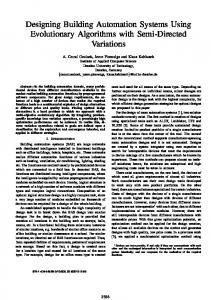
Fig. 7. Simplified representation as a composition of automata, of the behavioral model of an ME driver for a replicated tier. Computation of min-nodes and max-nodes is not represented.
an abstract view of the ME accordingly. i High-level information is output to expose an abstraction of the status of the managed system; it will be used to express management strategies and coordination policies (cf. Sections 6 and 7 below). At last, the behavioral model outputs the c lowlevel commands that trigger executions of methods of the operating code, in response to r high-level requests. The latter signals vehicle requests for changing the operating state of the ME, and will be output by synchronous nodes encoding management strategies (cf. Section 6 below). In the sequel, we represent behavioral models as (compositions of) BMAs with integer I/Os (cf. Section 2.1.1). Example. Fig. 7 depicts the behavioral model of a replicated tier driver. Associated operating code transmits monitoring data in the form of low-level notifications to the behavioral model: the Boolean signal node-added is raised once when a new node has finished starting up; similarly, node-repaired holds once when a node has been successfully repaired; #alive is a measure representing the number of nodes whose heartbeats have been successfully received for some fixed amount of time; conversely, #failures is the number of nodes whose heartbeats are missing; load-avg is a measure gathering the loads of the alive nodes constituting the tier (e.g., average of EWMAs). When high-level requests (upreq , downreq or repairreq ) hold, and according to the current state of the model, appropriate low-level commands (add, remove or repair) are output so as to trigger the required operations. Highlevel information signals are also output: the Boolean starting-up-node (resp. repairing-node) reflects the actual status of the driver, holding while a node is currently being started-up (resp. repaired), i.e., the corresponding acknowledgment notification node-added (resp. node-repaired) has not been received; load-avg, #alive and #failures are also part of the high-level information; finally, max-nodes and min-nodes reflect other status information that are computed internally. Note that when in states N and N’, if upreq ∧ repairreq holds, then both add and repair low-level commands are output by the model: it is assumed that the associated operating code is able to handle both requests simultaneously (i.e., to execute associated methods concurrently). On the
contrary, add and remove are never emitted during the same reaction, and an acknowledgment node-added is always required after an add operation to proceed with new upreq or downreq requests: the associated method is never reentered, and no remove operation can be started if an add operation is still in progress. (Note also that this example model is a slightly simplified one, and some additional signals must be added to properly handle error cases.)
5.4
Combining Multiple ME Drivers
Once the drivers for all the MEs have been developed (or taken from a library of pre-designed ones), they can be combined in order to make up the basis of an AMS software. The parallel composition of several behavioral models (as explained in Section 2.1) provides a global view of the managed system that can be exploited to reason about the state of a set of MEs. This composition forms a single reactive node, say BMs (for “Behavioral Models”), whose inputs (resp. outputs) are the union of all the inputs (resp. outputs) of its constituting behavioral model instances. The remaining design steps consist of making the associated pieces of operating code interact with BMs (i.e., feeding it with the appropriate low-level notifications and interpreting its low-level commands), and actually driving the MEs by generating high-level requests. BMs could be used directly as a whole synchronous program. Yet, in this case, one would need to develop other pieces of sequential software feeding it with high-level requests and monitoring its high-level information. On the other hand, BMs can also be further composed with other reactive nodes that read high-level information and generate high-level requests, to obtain the full decision logic as a synchronous program; this choice allows to further exploit the capabilities of reactive control techniques for property verification and enforcement. Whatever the case, the resulting program can be compiled to produce a tick, whose inputs comprise at least the set of low-level notifications of the behavioral models, and outputs include their respective low-level commands. The tick can further be integrated in an execution platform, as explained in Section 2.1.3.
BERTHIER et al.
r
n
High-level Requests
Low-level Notifications
9
Director (dk,i ) Behavioral Model (Mi )
High-level Information
N i
Low-level c Commands
Fig. 8. Synchronous composition of a director and the behavioral model it handles, for a managed entity MEi .
i
�
#alive load-avg min-nodes max-nodes
u/up
d/down D
d u u d
up down
r
U
u = max-nodes ∧ upper-threshold(load-avg, #alive) d = min-nodes ∧ lower-threshold(load-avg, #alive)
�
Fig. 9. Example stateful director dscaling,* .
In the two next sections, we focus on the decision logic (the part of the AMS software written as a synchronous program) by detailing a way to design synchronous nodes generating high-level requests from high-level information (the directors), and enforce coordination.
6 E XPLOITING THE M ODELS FOR AUTONOMIC M ANAGEMENT Í 6.1
Encoding Autonomic Management Strategies
The role of the directors is to encode autonomic management strategies by acting upon the system through the ME drivers. As sketched in Fig. 8, a director is a synchronous node computing high-level requests by means of the highlevel information output by its respective behavioral model. It may encompass some memory, and use this knowledge about the past to tune its decisions, or avoid instabilities. When it does not encapsulate memory, a director is a function in the mathematical sense (a single-state BMA), and we represent it as sets of equations for the sake of clarity. To enforce some degree of scalability, each director is designed independently of each other: i.e., a director must be designed to make decisions as if it were the only director handling a given ME. Also, even though directors are MEspecific, they come as separate synchronous nodes that can easily be reused across several AMSs. Example repair Director. Consider a tier driver that can concurrently allocate and start-up multiple nodes, i.e., able to handle new upreq (resp. repairreq ) requests without waiting for node-added (resp. node-repaired) acknowledgments — thus, one that is slightly more sophisticated than the one presented in Fig. 7. A possible example repair policy drepair,* is the following: request one replacement machine (set repair output signal) if there is a single failure and no machine is currently being repaired (#failures = 1 ∧ repairing-node), or if there are multiple detected failures (#failures > 1): repair = � i h� #failures = 1 ∧ repairing-node ∨ #failures > 1
Note the memory that this example repair director makes use of comes from its associated behavioral model through the signal repairing-node. Example Memoryless scaling Director. Using the same tier driver as in the previous example, a scaling policy dscaling,* can be expressed as follows: up = max-nodes ∧ upper-threshold(load-avg, #alive) down = min-nodes ∧ lower-threshold(load-avg, #alive)
where upper-threshold() and lower-threshold() represent basic arithmetic conditions deciding whether the system is overloaded or underloaded according to the load average and the number of alive nodes. (Notice one may need to ensure that up ∧ down always holds. In our context, this verification could be achievable statically by using verification techniques mentioned in Section 2.1.) Example Stateful scaling Director. Building on the above example scaling director, one can design a scaling director encapsulating some memory that requires the overload and underload conditions to hold twice in a row before adjusting the number of replica of the tier. We show such an example director in Fig. 9. 6.2
Exhibiting Directors’ Controllability
In order to be coordination-aware, the synchronous nodes encoding autonomic management strategies that we have described must exhibit some controllable inputs. As explained in Section 2.2, controlling a reactive node requires identifying among its inputs, those that provide some control over its behavior. The goal is to refrain directors from taking inconsistent decisions, or even to force some management decisions in certain situations. For our example, we restrict to the former case, and it is sufficient to add an approval signal that must hold in order for the decisions taken by the director to be effectively taken into account: the synthesized controller will therefore be able to inhibit the director’s behavior if it violates some invariant to ensure, or necessarily leads to undesirable operating states (cf. Section 7.3 below). Deciding whether a decision is controllable (i.e., can be inhibited) or not depends on its meaning and is highly director-specific. The idea is the following, depending on whether the director keeps track of some history or not. Principle in the Stateless Case. For each output o of stateless autonomic directors that is considered controllable, build a new version oapproved of the output by conjunction with an additional approval signal. Principle in the Stateful Case. In the case of a director with memory, approval signals can be added so that transitions are inhibited, not only their outputs: each guard formula of transitions considered controllable is translated with a conjunction as in the stateless case; in this way, the internal state of the director stays consistent with the control decisions. Note it is also possible to employ the technique described for the stateless case, so that the internal state of the director changes whatever the approval signal.
10
AUTHORS’ VERSION
okscaling i
#alive load-avg min-nodes max-nodes
d ∧ okscaling /down D
N
d u u d
u ∧ okscaling /up
up down
r
repairreq j = repairapproved
U
j
upreq j = downreq j = false
Fig. 10. Controllable version of the stateful scaling director of Fig. 9; see the latter Fig. for the definitions of local signals u and d.
Examples. Building up the previous example stateless directors, we consider that all high-level requests can be inhibited and are thus controllable. The approved versions of the request signals output by our example directors are then defined as: repairapproved = okrepair ∧ repair upapproved = okscaling ∧ up downapproved = okscaling ∧ down where okrepair and okscaling are new approval signals of the reactive nodes encoding the autonomic management policies drepair,* and dscaling,* , respectively. In the case of the stateful scaling director, we can choose to require an approval signal whenever a transition outputting requests up or down would be taken. In this case, the internal state of the director does not change on disapproval; we show a representation of this controllable director in Fig. 10. The approved versions of the request signals output by the latter example director can then be defined as: upapproved = up downapproved = down.
6.3
The high-level requests associated with a non-replicated tier Tj , hence for which a scaling strategy would be meaningless, are bound to a repair director as follows:
Combining Directors and ME Drivers
Recall now that for each ME, the appropriate directors must be instantiated and their input and output signals connected to the corresponding ME driver. Application to the Example. Going back to the illustrations of Fig. 5 and 8, for each tier Ti , generating the high-level requests consists in mapping the approved requests output by each director d*,i to the appropriate high-level inputs of the behavioral model Mi . Requests that are output by several directors are merged with a disjunction: assuming that the high-level request rreq belongs to the outputs of directors d1,i and d2,i (each outputting rapproved and rapproved re1,i 2,i spectively), then the effective high-level request input to Mi would be rreq i = rapproved ∨ rapproved . (Note that in the 1,i 2,i remainder of the article, synchronous signals are indexed with an identifier to denote the tier they are related to.) For instance, we straightforwardly obtain for each tier Ti where both scaling and repair strategies are to be combined: repairreq i = repairapproved i upreq i = upapproved i downreq i = downapproved i
7
E NFORCING C OORDINATION
Î, Ï
Coordination policies can be specified based on the set of behavioral models involved, and do not depend on management strategies. They are synchronous nodes encoding predicates with propositional formulas involving high-level information and low-level commands output by behavioral models, plus possibly some memory to express temporal properties. These predicates define invariants whose violation indicate inconsistencies. Next, as stated in Section 6.2, a controller ensuring the invariance of the coordination predicates can be synthesized if the nodes encoding the management strategies are sufficiently controllable: i.e., their controllable inputs (the approval signals in our case) provide enough means for controlling their decisions. In order to exemplify the principles explained in this section, we elaborate the two topmost layers (Î and Ï) of Fig. 5 for our running example. We concentrate here on logical invariants like mutual exclusions, and disscus further possibilities offered by our design in Section 9.1. 7.1
Ensuring Entity-level Coherence
Î
In our encoding of autonomic management strategies, an entity-level incoherence manifests as conflicting or extraneous operations on one ME. They can most often be avoided by ensuring the mutual exclusion between some working states and operations on the ME. Example. For each tier Ti in Fig. 5, the role of the tier-level predicates TPi is to specify these invariants. Considering the beharioral model for a tier represented in Fig. 7, one may want to ensure that simultaneous add and repair operations only occur in case of multiple failures, to avoid triggering an up-scaling while a node is only temporarily unavailable for example. The invariants to enforce are the following: � starting-up-nodei ∧ repair i � ⇒ #failuresi > 1 repairing-nodei ∧ add i ⇒ #failuresi > 1
An alternative policy would be to only allow simultaneous add and repair if some condition checking for a very high level of overload holds. With our example management strategies of Section 6, if a failure occurs on a single node in a replicated tier, thereby potentially causing a temporary overload until the node is repaired, then both add and repair operations could be performed simultaneously. Enforcing the invariants above would prevent one of such supernumerary operations. Another tier-level predicate worth ensuring avoids simultaneous down-scaling and repairing decisions if failures are detected: #failuresi > 0 ⇒ removei ∧ repair i
BERTHIER et al.
7.2
Ensuring Inter-entity Consistency
11
Ï
An inter-entity inconsistency manifests as independent directors handling distinct MEs with intrinsic side-effects, i.e., having remote impacts. Such inconsistencies are evidently ME-specific, since they depend on their intrinsic properties and behaviors. Example. The role of the inter-tier predicates IP→i+1 in Fig. 5 is to avoid potential remote impacts of working states of tiers T1 to Ti on tier Ti+1 : they prevent inconsistent operations on the latter based on the knowledge about the other tiers. For example, preventing down-scaling a tier if its underload may be a direct consequence of a failure in another tier requires the enforcement of invariants expressed in terms of the status of each of its predecessor tiers (ordered according to the service dependencies). Such a predicate on tier Ti+1 can be expressed as an implication forbidding removei+1 commands: i � � _ repairing-nodej ∨ #failuresj > 0 ⇒ removei+1 j=1
Here, repairing-nodej and #failuresj express the known status of all tier Tj preceding Ti+1 . Note that, although it is not useful for our basic n-tier example, it is conceivable to express other kinds of interentity coordination predicates in situations where remote impacts do not only follow the workflow, but are somehow hierarchical or even cyclic; in particular, such predicates could take cross-layer impacts of the state of other MEs into account. 7.3
Producing the AMS Software
In order to obtain the AMS software, and similarly to the case explained in Section 5.4, the set of all behavioral models, their respective directors and entity-level coordination predicates, as well as the inter-entity ones (levels Ì, Í, Î and Ï in Fig. 5), are combined using a parallel composition to form a synchronous node DL. Then, a DCS tool (cf. Section 2.2) is employed in order to synthesize a controller C to ensure the invariance of the coordination predicates by generating the controllable inputs of the directors (the approval signals in our example — cf. Section 6.2). C is then composed with DL to form another synchronous program, say DL’, encoding the coordinated decision logic of the AMS. As stated in Section 2.2, C is maximally permissive, thus imposes the least possible restrictions on the management strategies to enforce the invariance of the coordination predicates. The final AMS software results from the combination of the compiled DL’ program (say, tick), the operating code (Ë) of the ME drivers, plus the integration code that transmits low-level notifications and commands between the two.
8
I MPLEMENTATION AND VALIDATION
The main purpose of our proposal is to statically guarantee the absence of coordination issues. As a result, to validate our design, it is more important to point out its practicality with a proof-of-concept implementation and check the correctness of its behavior, rather than carrying out thorough
performance evaluations and comparing them with existing solutions. In order to evaluate the practicality and efficiency of our approach, we have implemented sams2 , a tool for designing autonomic management infrastructures based on a fault-tolerant middleware and reactive control techniques. In particular, we have integrated in sams a slightly more elaborate version of the working example detailed throughout this article; notably, the tier drivers handle error cases and involve more low-level notifications. In order to ease the (un-)deployment and configuration of all tiers, an additional automaton was also added, outputting appropriate sequences of high-level requests. We have checked the correctness of its behavior3 by conducting intensive tests (e.g., involving many simultaneous failure injections under various workloads). We now describe technical details concerning the tool, explain our choice for workload generation, and exemplify its behavior by detailing execution traces. 8.1
Implementation Choices and Description
8.1.1 Distributed Execution Platform The A3 [25] fault-tolerant middleware suits the implementation of distributed AMS software. Implemented using Java, it provides us with reliable asynchronous messaging, as well as means for specifying reactive agents. Also, messages exchanged between A3 agents are delivered according to a causal order. Each agent features a reaction method handling any new message it receives. These methods are executed atomically and as transactions. This execution platform suits our needs for implementing the decision code (see Section 2.1.3) that receives the low-level notifications (event notifications and measures), executes the tick encoding the decision logic, and translates the resulting low-level commands into actual executions of sequential code. The operating code can also be implemented by means of communicating agents distributed among the managed nodes. 8.1.2 Implementation Details Decision Logic. The tick object has been implemented by using the Heptagon/BZR synchronous language [23], featuring means for describing behaviors such as the one described in Fig. 7, plus the director strategies and coordination policies as denoted through Sections 6 and 7. Besides, it allows the expression of invariants that can then be enforced using a DCS tool. In practice, the tick is the result of the compilation of a synchronous program exclusively involving a set of synchronous nodes whose textual representations are highly related to the automaton and equations above. Integration & Operating Code. In our implementation, sensors and actuators are agents hosted in a JVM executing on the remote nodes also running the application processes (e.g., Apache, Tomcat), and a JVM referred to as the center process hosts the other agents: the tier and muxer agents, plus the unique tick agent: 2. Available and further detailed at http://sams.gforge.inria.fr/. 3. Though the formal nature of its internal logic provided us with great confidence about the management decisions taken, we still needed to develop and assess the operating code of the tier drivers.
12
AUTHORS’ VERSION
Tier agents are responsible for handling the tiers’ remote nodes: they react to messages transmitting low-level commands, by (un-)deploying distant sensor and actuator agents, plus application service files; they also handle the life-cycle of the application processes (e.g., configuration, start-up). Tier agents send impulses (e.g., node-added, node-repaired) to the tick agent. Muxer agents are in charge of gathering heartbeats and load measures, and periodically averaging them, counting missing ones and sending measures (e.g., #alive, #failures, load-avg) to the tick agent. The tick agent plays the role of the integration code detailed in Section 2.1.3: it receives messages carrying either a measure or an impulse from the other agents, and decides to execute the tick both (i) as soon as an impulse input is delivered and (ii) after some fixed period of inactivity (when no impulse has been received for some time — 15s in our experiments); the latter case allows to take decisions based on variations of measurement values only. 8.2
Validation
8.2.1 Experiment Setup The successive tiers used for the experiments are the ones already detailed in Section 3.1. Each tier is associated with a repair director; all replicated ones (Ttomcat and Tmysql ) are also handled by a scaling director. Every node involved is a mono-processor virtual machine running a basic Linuxbased server system. The center process runs on a dedicated VM, and a separate physical machine is used to inject the workload. All VMs are spread among four multi-core blades running VM monitors also hosting other unrelated VMs inducing limited loads, and do not migrate during the experiments. Each of the two clusters for replicated tiers Ttomcat and Tmysql comprises three VMs hosted on distinct blades. Allocation of VMs in individual clusters is performed according to a round-robin policy. 8.2.2 Workload Generation To develop the operating code of the tier drivers for our prototype, we needed a setup for which we could obtain “reproducible” and stable workloads. In effect, we needed to achieve the following objectives: First, the generation of enough workload was required to stress the whole system enough to trigger up-sizings. Second, in order to check that the management decisions were correctly coordinated, we needed to be able to inject failures at instants always leading to inconsistent management decisions under noncoordinated management. Last, we wanted all experiments to be fast and precisely reproducible as we used them to debug the operating code of the prototype; sams is indeed very lightweight in terms of required computation resources, and is thus able to frequently react to changes in the managed system by using rather high sensor sampling and reaction rates (e.g., performing one measurement of every sensor every 15s or much less). We had based the evaluations of our former works [9, 10, 11] on R UBiS’s multi-tier web application (on time scales incompatible with our debugging objective though), hence we had some expertise on its functioning. However, after having conducted some experiments with R UBiS’s
client emulator, we drew the conclusion that it was unable to fulfill all the above objectives at the same time: to develop sams and carry out our experiments, we needed to generate a rather predictable workload instead of subjecting the system to sequences of requests imitating human users. Indeed, when the number of machines involved is quite limited, such realistic workloads are hardly stable enough to allow failure injections at instants where they inevitably cause incompatible management decisions. We have thus modified the auction site provided by R UBiS by adding and exclusively using three custom servlets: two of them generate either heavy read or write requests on the database, and the other involves heavy computations at the Tomcat level. Workload is then injected by sending HTTP requests to the Apache server, each triggering the execution of one of our three custom servlets. The number of requests of each kind per second varies randomly, yet globally follows a ramp-up phase, stabilizes for some time, then decreases4 . 8.2.3 Behavioral Comparisons The collected data consist of CPU utilization percentages on each VM involved in the experiment, to get a basic yet convenient representation of their activity. To illustrate the behavior of the AMS software, we inject a failure at the level of the Tapache tier by manually killing the relevant processes on its unique node (i.e., the application service processes and the JVM hosting all the AMS remote agents)5 while each replicated tier of the application is highly loaded and execute on two nodes. We present two of such executions to exhibit the efficiency of the coordination policies6 . For the first execution only, the tick is produced by replacing the coordination predicates detailed in Section 7 by tautologies. In other words, with the first setup, no constraint is imposed on the directors’ decisions (the approval signals always hold), whereas the second setup enforces the coordination policies. Expected Results. The resulting traces should exhibit useless management operations (w.r.t. our overall goal of reducing the number of used resources) during the noncoordinated execution only, hence exemplifying the benefits of coordination policies enforcement. 8.2.4 Detailing Execution Traces We plot in Fig. 11 and 12 the data measured by applying the protocol described previously with a management software respectively incorporating either a non-coordinated or a coordinated tick. In both cases, the CPU utilization of the VM executing sams’ center process is not shown as it is almost unnoticeable (except during file transfers, that would take place whatever the management infrastructure). For each replicated tier up-scaling (resp. down-scaling) decisions are denoted Ú (resp. Ø ). 4. Full source code of the modified R UBiS servlets, configuration files for the injection tool JMeter (http://jmeter.apache.org/), documentation and scripted tests, are also available at http://sams.gforge.inria.fr/. 5. We let the VMs running to keep load measures correctly synchronized; to ease readability, the apache node is reused to deploy a new Apache service after the failure. 6. Although we conducted a substantial amount of experiments with coordinated management without ever noticing inconsistencies.
BERTHIER et al.
13
CPU utilization (EWMA %) / time (s) apache
80
useless down-scaling operations were inhibited during the restoration of the Apache service: half as much scaling operations occurred during this execution than in the noncoordinated case.
failure
20
tomcat-1
80
Ø
20
tomcat-2
80
Ú
20
tomcat-3
80
Ú
Ø
20
mysql-proxy
80 20
mysql-1
80 20
mysql-2
80
Ú
Ø
20
mysql-3
80
Ú
Ø
20
0
50
100
150
200
250
300
350
400
450
Fig. 11. Execution with non-coordinated management. CPU utilization (EWMA %) / time (s) apache
80
From these two sets of experiments, we can conclude that apart from being robust and efficient, our implementation of the design we propose exhibits the expected behavior and allows to enforce coordination of management decisions without any noticeable impact on the performance of the management infrastructure.
failure
20
tomcat-1
80
Ø
20
tomcat-2
80
8.2.5 Realistic Experiments In order to validate our design for the management of a system under more “realistic” workloads, we eventually conducted experiments using R UBiS’s client emulator. After tuning some measurement parameters of the prototype (such as weighting factors of EWMA computations) to accommodate for the more changing loads induced by the emulator, we could obtain results similar to the ones presented above, yet less illustrative since generally involving sizing operations on the Tmysql tier only7 . Comparing execution traces and throughput results from the perspective of the user as reported by the emulator with and without failure injections, shows that sams reacts to failures almost as quickly as its measurement probes allow it to; i.e., the 15s maximum period between two executions of the decision logic set up for the experiments did not prevent it to react to failures faster.
Ú
20
tomcat-3
80 20
9
mysql-proxy
80 20
mysql-1
80 20
mysql-2
80
Ú
Ø
20
mysql-3
80 20
0
50
100
F URTHER D ISCUSSIONS
Let us now discuss further aspects of our design method, including some limitations as well as some possible extensions that we think emphasize its potential.
150
200
250
300
350
400
450
Fig. 12. Execution with coordinated management.
Notice that when new Mysql nodes are added, they are meant to handle read-only requests exclusively; this is the reason why the CPU load is not equivalently balanced between them. Note also that the high load that can be observed on the mysql-1 node during start-up of mysql-2 and mysql-3 is due to the duplication of the database. Non-coordinated Execution. In the trace of Fig. 11, the problem arising when scaling and repairing decisions about all tiers are not coordinated appears clearly: we observe down-scaling operations of both Ttomcat and Tmysql tiers during the underload subsequent to the failure of the apache node. These operations were undone straight after the latter was repaired. Coordinated Execution. We reproduce in Fig. 12 the same kind of data when the AMS software incorporates the tick with enforced coordination policies. First of all, scaling operations still happened under “normal” situations, i.e., when no failures were detected. However, and as expected,
9.1
On the Identification of Coordination Policies
From our own experience, it is clear that identifying a complete set of predicates only expressing undesired situations is still a rather difficult task. This is actually a very general design problem affecting any methodology relying on verification techniques (as well as manual programming). Our approach provides help in designing and synthesizing discrete controllers for the modeled behaviors and declared objectives. There remains for the designer to check the complete coverage of intended requirements on the system. This situation is comparable to what happens in other formal methods, like verification by model-checking, that also considers state-space exploration of given models and properties: the latter also have to be specified with some completeness w.r.t. the application. Also in classical continuous control, the adequateness of equations-based models involves expertise from the designer, who has to know the target system. Similarly to these other design support methods, simulation and analysis of the results are needed in a complete design process. An experiment involving industrial data center management goals would provide interesting methodological feedback. Yet, here it can be noted that this is a collaborative 7. Some reports generated by R UBiS’s client emulator are available at http://sams.gforge.inria.fr/rubis-benchs/.
14
work between authors with different backgrounds, and that the authors with a systems background were naturally not experts in reactive programming nor discrete control; they however acquired practical competence rapidly by specifying models and coordination policies gradually, supported by the programming language, and validating them by simulation or experiments. Further than this particular experience, we claim that several aspects and extensions of our design method permit to overcome the problem of identifying (close to) necessary and sufficient coordination policies: Using Off-the-shelf Entity-level Consistency Predicates. First, remark that entity-level coordination predicates only depend on the behavioral model they are associated with. As a result, they are reusable and one can imagine to provide a library of pre-designed ones accompanying ME drivers. Using Stochastic Simulation Techniques. Second, the family of synchronous languages comes with existing tools that allow extensive simulations of the models, and thus designtime detection of conflicting situations through simulations. An example of such tool is L UTIN [15], that takes as input a specification of a system to simulate in the form of a stochastic reactive program. Roughly, the identification process would consist in assembling the behavioral models into a synchronous node, writing a stochastic program coarsely simulating the managed system by reading the low-level commands of the behavioral models and outputting their low-level notifications and high-level requests accordingly. Simulating the two in combination would then permit to monitor the behavior of the simulated model to identify undesirable situations. Using this technique, identified coordination predicates to enforce can then be incrementally added to the stochastic program, that would then generate test sequences enforcing them for subsequent simulations. Furthermore, the aforementioned simulation tools can also be used to check the effective progress of the reactive program encoding the decision logic of the AMS, hence assessing the compatibility of its expected behaviors and the coordination policies (cf. Section 2.2). Towards Higher-level Coordination Policies. So far, we focused on the expression of discrete, logical coordination policies encoding “undesirable situations”. However, in our case these situations depict redundant or useless decisions, that could be expressed more easily if appropriate quantitative information was available in the behavioral models (like a cost associated with the use of a VM, or the cost of starting one or turning it off). Existing synthesis objectives targeting the optimization of cost functions [26] could also be considered as a way of enforcing some degree of coordination. Moreover, the DCS tool we used during the development of our method prevented us from enforcing invariants directly involving quantitative aspects of the system, such as workload variations or energy consumption. Yet, as already mentioned in Section 2.2, recent developments [24] led to a DCS technique capable of handling reactive programs involving such properties. Our approach could benefit from these advances for the design of controllers ensuring quantitative properties of the system.
AUTHORS’ VERSION
9.2
On Modularity and Distribution
We recognize our approach suffers from the centralized design and execution of the decision logic; we now elaborate on these two issues. Towards Modular Designs. Concerning design, multiple layers are a natural feature in targeted systems, and they have to be coordinated while managing various granularities. We have identified that the different levels of abstraction have an impact on models, where automata can be kept concise at each of the levels, and thereby enable scalability of the size-sensitive algorithms: this point can benefit from the modular DCS and compilation offered by Heptagon/BZR. Modeling different levels can also impact time granularities: the flows of values in upper layers can be much less frequent than at lower levels. The implementation of such modular decision logic can be distributed and desynchronized, in the sense that synchronizations occur only around exchanged flows: preliminary experiments have been in the application-specific context [27], and could be leveraged in the more general framework proposed in this work. Towards Distributed Execution. Apropos of execution, we claim there are two coherent ways to tackle this problem: (i) a priori, by producing multiple interacting tick objects; (ii) a posteriori, by distributing the resulting tick itself. Indeed, the specific execution mechanisms required to execute synchronous programs mentioned in Section 2.1.3 do not prevent from either making several tick objects run concurrently (e.g., for fault-tolerance), or distributing the internals of a tick. In both cases, properties of the distributed execution platform need to be taken into account. For instance, the causal ordering of message deliveries, possibly over lossless communication channels, is a property of interest to design multiple interacting synchronous programs designed in a centralized manner. An interesting trail is also to exploit the globally asynchronous locally synchronous nature [28] of distributed execution platforms8 , in the spirit of the work of Carlsson et al. [29] for the design of hardware circuits. The works of Halbwachs and Baghdadi [30] and Bouhadiba et al. [31] are inspiring w.r.t. a priori distribution. Already existing techniques developed for multitask implementations [17], or in the context of distributed reactive systems [19, 32], could be extended for a posteriori distribution. In the latter case, the decision logic would still be designed as if its execution were centralized, and DCS would also apply directly. 9.3
Positioning w.r.t. Classical Control
As mentioned in the Introduction, the support offered by our approach is complementary to equations-based control in the sense that it does not replace classical control techniques; e.g., based on PID (Proportional, Integral, Differential) or differential equations. Yet on the one hand it supports its safe implementation, and on the other hand it complements it with support regarding the event-based and logical aspects, related to discrete control. 8. Systems made of several computing units behaving as classical synchronous programs, communicating through FIFOs, and whose relative clock drifts can be bounded.
BERTHIER et al.
We indeed provide high-level language support for the safe implementation of equations-based control: actually the reactive languages we use have been designed especially to implement cyclic control loops such as designed using classical control, in the domain of embedded and realtime systems; control equations and block-diagrams are implemented as data-flow nodes. These languages provide designers with programming and implementation environments; the design of the controllers continues to rely on control theory, yet can also benefit from high-level specification, compilation to different execution platforms, simulation or verification (e.g., using model-checking). We provide as well additional support for the design of discrete controllers, on the part of dynamics belonging to Discrete Event Systems (DES), involving discrete states (e.g., in finite sets) and transitions governed by events, such as represented typically by Petri nets or automata (playing the same role as equations); e.g., automata can be used to manage the switching between various modes of control. Our approach relies on compilers and tools where part of the discrete control problem can even be solved automatically: we use automated synthesis of Supervisory Controllers for DES that are, by construction, correct in the sense that they enforce their objectives, and optimal in the sense that they are maximally permissive. These tools thereby alleviate the burden of systems designers. The models we use also feature the management of numerical weight values associated with state or event variables, that can support the modeling of some quantitative aspects: it is naturally less expressive than models in classical control, yet has the advantage of being integrated in the automated controller synthesis framework. Regarding coordination of multiple loops, the design of Multiple-Input Multiple-Output (MIMO) or optimal loops is an answer involving control techniques and analytical work based on differential equations that is necessary to obtain good properties. It is a top-down approach for the redesign of combined loops. We propose a complementary bottom-up approach, that favors the modular design of complex controllers through the assembly and coordination or more basic ones, leading to a better reusability. Obtaining guarantees that the assembled control loops will perform optimally still requires the above mentioned analytic work, e.g., applying results from distributed control theory. Our approach provides a framework facilitating the bottom-up reuse of control elements, in a perspective of modularity in the sense common in computer science. Both approaches can be used in a complementary way. The kind of properties for which we do support safe design, with behavioral guarantees on the controlled behavior, are typical of DES: invariance of a subset of the discrete state space, characterized by a predicate, or reachability of some states, and generally safety w.r.t. sequences of events and states. A perspective could be to consider the use of hybrid systems, i.e., modeling continuous and discrete dynamics together. For them however the DCS algorithms are much more costly, when they are possible at all: this is an additional motivation to adopt modular approaches.
15
10
R ELATED W ORKS
Two families of contributions are related to our proposal. We first review current solutions for the coordination of AMSs, and precise what are the relative improvements of our proposal. Then, we survey other applications of reactive control systems design, and particularly discrete controller synthesis, to the control of computing systems. 10.1
Coordination of AMSs
Few works have investigated the coordination of AMSs, mostly by extending usual software engineering techniques and models. Nathuji and Schwan [33] propose VirtualPower to address the coordination of power management policies at the level of VM monitors. It allows each VM to specify its own power-management policy (e.g., processor frequency scaling), and globally handles consolidation and VM migrations based on a set of rules involving platform-specific mechanisms. VirtualPower is designed as a set of distributed driver components dedicated to the coordination of platform-level power management, plus a centralized component dedicated to global coordination of VM migrations. Being application agnostic, this approach cannot take intrinsic workload dependencies between VMs into account to coordinate decisions. vManage [34] is a coordination approach close to the previous one, that loosely couples platform and virtualization management to improve energy savings and QoS while trying to reduce VM migrations. vManage involves a set of components making use of “coordinator” and “stabilizer” objects, and services (e.g., registry and proxy) provided by a centralizing management node. The various objects seem intricate since they are multi-threaded and need to exchange data to take decisions, yet the authors give no clue about their actual design. Aldinucci et al. [35] advance a method to hierarchically compose managers, each dedicated to fulfilling nonfunctional concerns. Managers are programmed as Fractal components using internal rules to choose management actions, and operate in either active or passive modes depending on the satisfaction of some condition; rules are prioritized to handle conflicting cases local to a particular manager. The proposal also requires implementing managers offering ways to communicate in various ways, notably according to two-phase negotiation protocols. Contracts express quantitative objectives for measures about the managed system, and must be “split” by composite managers. Besides the fact that the necessary communications between managers significantly complicate their design, the authors do not demonstrate the effectiveness of their approach when considering multiple concerns. They also recognize the splitting of contracts, when possible, is most often an intricate task yet to be addressed. Das et al. [36] use a multi-criteria utility function to assign some quantitative “desirability” metric to operating states. They use it to address the coordination of multiple autonomic managers for power/performance tradeoffs. Based on multi-agent systems, their solution requires a model learning phase involving tedious manual experi-
16
ments, and without guarantees about the behavior of the resulting AMS. Heo and Abdelzaher [37] propose AdaptGuard, a software service aiming at countering some false assumptions made during AMS software design without any a priori model of the managed system. It monitors measurements performed by the AMS software and the quantities it sends to actuators, and tries to discover correlations during a learning phase. It is then able to detect violations of causality assumptions, and then take custom and supposedly stable backup control decisions to counter it. Their work targets instabilities that are due to faults having unanticipated effects, or that occur in nominal mode when adaptation mechanisms are pairwise incompatible; so it is very efficient at handling persistent coordination problems (that would last until corrected). Although the latter constitute an interesting class of instabilities, our objective is different as we target logically redundant or useless discrete decisions, that are transient problems. Regarding other kinds of platforms, surveys and studies about autonomic management for grids [38], clouds [39], and networks [40], show similar concerns about coordination issues, and review solutions analogous to the ones above in this section. In any case, the emergent global behavior resulting from a combination of managers handling different concerns is hardly predictable. In this respect, one significant advantage of our proposal is the formal foundations of the models it involves, allowing us to provide guarantees about the absence of coordination issues. As stated in Section 1.3, we [9, 10, 11] already applied discrete control techniques to coordinate legacy autonomic managers. We proceed by modeling existing managers in a synchronous language, and execute the resulting tick by intercepting events occurring in the managed system before they are transmitted to the managers. We then apply DCS to decide whether management decisions could lead to violations of desired invariants; in such a case, the tick outputs dedicated signals to inhibit executions of managers’ sequential code (methods). Whereas we only used synchronous programming to model existing managers very abstractly in this former work, the proposal we present in this article goes further as we program the entire AMS’s decision logic using a synchronous language, thus benefit more from the formal nature and associated guarantees of such high-level programs. We also investigate more on software architectures articulated around synchronous programs, as one constitutes the core of the AMS software in our new solution. Indeed, as explained in Section 2.1.3, although such programs bring considerable guarantees about the behavior of the design, they still need to be correctly integrated in an execution platform, fed with appropriate inputs, and connected to mechanisms triggering the execution of sequential code (in our case, pieces of operating code). Note that all the solutions above require the presence of a particular piece of software centralizing some portions of the decision logic, and are hence subject to availability issues. Although our own design suffers from the same problem, we claim it paves a way to the conception of AMS softwares overcoming this issue.
AUTHORS’ VERSION
10.2
Controlling Computing Systems with DCS
DCS techniques have already been applied in other contexts to control computing systems. For instance, Wang et al. [41] use DCS algorithms on Petri net models to insert additional control places in multi-threaded programs in order to avoid deadlocks. Altisen et al. [42] put forward the use of DCS techniques to build a property enforcing layer to impose global constraints on the behavior of devices otherwise driven independently. Still at the level of resource management, Berthier et al. [43] propose a solution to build a paravirtualization layer enforcing global control on resources. They use automata to model the resources, and rely on DCS techniques to enforce the control policy. Ryzhyk et al. [44] use a related technique to synthesize device drivers from interface and behavioral specifications (that are very close to automata); the resulting code is correct by construction, modulo the correctness of the specifications. More recently, Cano et al. [45] used DCS techniques to verify and enforce coordination of ECA rules by translating them into a reactive program with contracts.
11
C ONCLUSIONS AND F UTURE W ORKS
We have presented a new approach for the design of AMS software, resulting from an extension of former works by Gueye et al. [9, 10, 11]. Inspired by reactive control techniques, it is based on synchronous programming and discrete controller synthesis. These techniques allow the specification of the managed system with structured highlevel languages. Since they have a formal semantics, these languages also provide means to efficiently deal with coordination issues by statically enforcing invariants. We evaluated the practicality and efficiency of our proposal with an implementation. We already discussed some extensions for our solution in Section 9. We now review other trails that we think are interesting to investigate. First, the models involved in our implementation also make it suitable for the design of efficient automata-based deployment engines as in Engage [46] or similarly to the work of Cuadrado et al. [6]. We also plan to extend the prototype and carry out experiments for cross-layer coordination of autonomic management strategies. In particular, developing ME drivers for physical resources (e.g., sets of blades) would allow the integration of consolidation strategies as well as facility-related events handling (e.g., loss of cooling). Second, our design provides a suitable platform for experimenting modular control [22] to overcome potential scalability issues. Indeed, due to the computational cost of DCS algorithms, it could be interesting to be able to synthesize and reuse controllers enforcing entity-level coordination at first, and then synthesize additional controllers enforcing inter-entity consistency, in a way similar to some of our former work reported by Delaval et al. [47]. Next, it would also be interesting to automatically generate the behavioral models and management strategies, or even the coordination policies, from dedicated languages like the one proposed by Rosa et al. [5]. Based on a highlevel description of adaptable components, adaptation policies and goals involving performance indicators, they propose to generate a set of adaptation rules interpreted at runtime by a dedicated AMS software. As their proposal cannot
BERTHIER et al.
handle dependencies between adaptable components, we think that our design might be of interest to overcome this limitation. At last, automatic generation of the operating code from high-level descriptions might also be a goal of interest.
ACKNOWLEDGMENTS This work was supported by the French ANR project CtrlGreen (ANR-11-INFR 012 11), funded by ANR INFRA and MINALOGIC.
R EFERENCES [1] [2] [3]
[4]
[5]
[6] [7] [8]
[9]
[10]
[11]
[12] [13]
[14]
[15] [16]
J. O. Kephart and D. M. Chess, “The Vision of Autonomic Computing,” Computer, vol. 36, pp. 41–50, Jan. 2003. M. C. Huebscher and J. A. McCann, “A survey of autonomic computing—degrees, models, and applications,” ACM Comput. Surv., vol. 40, pp. 7:1–7:28, Aug. 2008. E. Bruneton, T. Coupaye, M. Leclercq, V. Qu´ema, and J.-B. Stefani, “The FRACTAL component model and its support in Java: Experiences with Auto-adaptive and Reconfigurable Systems,” Softw. Pract. Exper., vol. 36, pp. 1257–1284, Sep. 2006. G. Tesauro, D. M. Chess, W. E. Walsh, R. Das, A. Segal, I. Whalley, J. O. Kephart, and S. R. White, “A Multi-Agent Systems Approach to Autonomic Computing,” in Proceedings of the 3rd International Joint Conference on Autonomous Agents and Multiagent Systems - Volume 1, ser. AAMAS ’04. Washington, DC, USA: IEEE Computer Society, 2004, pp. 464–471. L. Rosa, L. Rodrigues, A. Lopes, M. A. Hiltunen, and R. Schlichting, “Self-Management of Adaptable Component-Based Applications,” IEEE Trans. Softw. Eng., vol. 39, no. 3, pp. 403–421, Mar. 2013. F. Cuadrado, J. C. Duenas, and R. Garcia-Carmona, “An Autonomous Engine for Services Configuration and Deployment,” IEEE Trans. Softw. Eng., vol. 38, no. 3, pp. 520–536, May 2012. J. O. Kephart, “Research Challenges of Autonomic Computing,” in Proceedings of the 27th International Conference on Software Engineering, ser. ICSE ’05. New York, NY, USA: ACM, 2005, pp. 15–22. D. Harel and A. Pnueli, “Logics and Models of Concurrent Systems,” K. R. Apt, Ed. New York, NY, USA: Springer-Verlag New York, Inc., 1985, ch. On the Development of Reactive Systems, pp. 477–498. ´ Rutten, “Component-based AutoS. Gueye, N. De Palma, and E. nomic Managers for Coordination Control,” in Proceedings of the 15th International Conference on Coordination Models and Languages, ser. Lecture Notes in Computer Science, R. De Nicola and C. Julien, Eds. Berlin, Heidelberg: Springer-Verlag, Jun. 2013, vol. 7890, pp. 75–89. ´ Rutten, A. Tchana, and D. Hagimont, S. Gueye, N. De Palma, E. “Discrete control for ensuring consistency between multiple autonomic managers,” Journal of Cloud Computing: Advances, Systems and Applications, vol. 2, no. 1, p. 16, 2013. ´ Rutten, A. Tchana, and S. M.-K. Gueye, N. De Palma, E. N. Berthier, “Coordinating Self-sizing and Self-repair Managers for Multi-tier Systems,” Future Gener. Comput. Syst., vol. 35, pp. 14–26, Jun. 2014. A. Benveniste, P. Caspi, S. Edwards, N. Halbwachs, P. Le Guernic, and R. De Simone, “The Synchronous Languages Twelve Years Later,” Proceedings of the IEEE, vol. 91, no. 1, pp. 64–83, 2003. P. Caspi, D. Pilaud, N. Halbwachs, and J. A. Plaice, “LUSTRE: a declarative language for real-time programming,” in Proceedings of the 14th ACM SIGACT-SIGPLAN Symposium on Principles of Programming Languages, ser. POPL ’87. New York, NY, USA: ACM, 1987, pp. 178–188. A. Benveniste, P. Bournai, T. Gautier, M. Le Borgne, P. Le Guernic, and H. Marchand, “The SIGNAL declarative synchronous language: controller synthesis and systems/architecture design,” in Proceedings of the 40th IEEE Conference on Decision and Control, ser. CDC ’01, vol. 4, 2001, pp. 3284–3289. P. Raymond, Y. Roux, and E. Jahier, “Specifying and Executing Reactive Scenarios With Lutin,” Electron. Notes Theor. Comput. Sci., vol. 203, pp. 19–34, Jun. 2008. SCADE, “Safety Critical Application Development Environment,” http://www.esterel-technologies.com/products/scade-suite/.
17
[17] P. Caspi, N. Scaife, C. Sofronis, and S. Tripakis, “Semanticspreserving multitask implementation of synchronous programs,” ACM Trans. Embed. Comput. Syst., vol. 7, pp. 15:1–15:40, Jan. 2008. [18] F. Maraninchi and Y. R´emond, “Argos: An Automaton-based Synchronous Language,” Comput. Lang., vol. 27, no. 1-3, pp. 61– 92, Apr. 2001. [19] P. Caspi and A. Girault, “Execution of Distributed Reactive Systems,” in Proceedings of the 1st International Euro-Par Conference on Parallel Processing, ser. Euro-Par ’95. London, UK, UK: SpringerVerlag, 1995, pp. 15–26. [20] P. Ramadge and W. Wonham, “The Control of Discrete Event Systems,” Proceedings of the IEEE, vol. 77, no. 1, pp. 81–98, 1989. [21] H. Marchand, P. Bournai, M. L. Borgne, and P. L. Guernic, “Synthesis of Discrete-Event Controllers Based on the Signal Environment,” Discrete Event Dynamic Systems, vol. 10, pp. 325–346, Oct. 2000. ´ Rutten, “Contracts for modular [22] G. Delaval, H. Marchand, and E. discrete controller synthesis,” in Proceedings of the ACM SIGPLAN/SIGBED 2010 Conference on Languages, Compilers, and Tools for Embedded Systems, ser. LCTES ’10. New York, NY, USA: ACM, 2010, pp. 57–66. ´ Rutten, and H. Marchand, “Integrating Discrete [23] G. Delaval, E. Controller Synthesis into a Reactive Programming Language Compiler,” Discrete Event Dynamic Systems, vol. 23, no. 4, pp. 385–418, Dec. 2013. [24] N. Berthier and H. Marchand, “Discrete Controller Synthesis for Infinite State Systems with ReaX,” in 12th Int. Workshop on Discrete Event Systems, ser. WODES ’14. IFAC, May 2014, pp. 46–53. [25] L. Bellissard, N. de Palma, A. Freyssinet, M. Herrmann, and S. Lacourte, “An Agent Platform for Reliable Asynchronous Distributed Programming,” in Proceedings of the 18th IEEE Symposium on Reliable Distributed Systems, ser. SRDS ’99. Washington, DC, USA: IEEE Computer Society, 1999, pp. 294–295. [26] H. Marchand and M. Le Borgne, “The Supervisory Control Problem of Discrete Event Systems using polynomial Methods,” IRISA, Tech. Rep. 1271, Oct. 1999. ´ Rutten, “Distributed Execution of [27] G. Delaval, S. Gueye, and E. Modular Discrete Controllers for Data Center Management,” in 5th Int. Workshop on Dependable Control of Discrete Systems, ser. DCDS ’15. IFAC, May 2015, pp. 139–146. [28] D. Chapiro, “Globally-asynchronous Locally-synchronous Systems,” Ph.D. dissertation, Stanford University, Stanford, CA, USA, Oct. 1984. [29] J. Carlsson, K. Palmkvist, and L. Wanhammar, “Design flow for Globally Asynchronous Locally Synchronous Systems using Conventional Synchronous Design Tools,” Transactions on Circuits and Systems, vol. 5, no. 7, pp. 953–960, 2006. [30] N. Halbwachs and S. Baghdadi, “Synchronous Modelling of Asynchronous Systems,” in Proceedings of the Second International Conference on Embedded Software, ser. EMSOFT ’02. London, UK, UK: Springer-Verlag, 2002, pp. 240–251. ´ Rutten, “Synchronous [31] T. Bouhadiba, Q. Sabah, G. Delaval, and E. control of reconfiguration in fractal component-based systems: a case study,” in Proceedings of the 9th ACM International Conference on Conference on Embedded Software, ser. EMSOFT ’11. New York, NY, USA: ACM, 2011, pp. 309–318. [32] A. Girault and C. M´enier, “Automatic Production of Globally Asynchronous Locally Synchronous Systems,” in Proceedings of the Second International Conference on Embedded Software, ser. EMSOFT ’02. London, UK, UK: Springer-Verlag, 2002, pp. 266–281. [33] R. Nathuji and K. Schwan, “VirtualPower: coordinated power management in virtualized enterprise systems,” in Proceedings of twenty-first ACM SIGOPS Symposium on Operating Systems Principles, ser. SOSP ’07. New York, NY, USA: ACM, 2007, pp. 265–278. [34] S. Kumar, V. Talwar, V. Kumar, P. Ranganathan, and K. Schwan, “vManage: loosely coupled platform and virtualization management in data centers,” in Proceedings of the 6th International Conference on Autonomic Computing, ser. ICAC ’09. New York, NY, USA: ACM, 2009, pp. 127–136. [35] M. Aldinucci, M. Danelutto, and P. Kilpatrick, “Autonomic Management of Non-functional Concerns in Distributed & Parallel Application Programming,” in Proceedings of the 2009 IEEE International Symposium on Parallel & Distributed Processing, ser. IPDPS ’09. Washington, DC, USA: IEEE Computer Society, 2009, pp. 1–12. [36] R. Das, J. O. Kephart, C. Lefurgy, G. Tesauro, D. W. Levine, and H. Chan, “Autonomic multi-agent management of power and performance in data centers,” in Proceedings of the 7th International Joint
18
[37]
[38]
[39] [40]
[41]
[42]
[43]
[44]
[45]
[46]
[47]
AUTHORS’ VERSION
Conference on Autonomous Agents and Multiagent systems: industrial track, ser. AAMAS ’08. Richland, SC: International Foundation for Autonomous Agents and Multiagent Systems, 2008, pp. 107–114. J. Heo and T. Abdelzaher, “AdaptGuard: guarding adaptive systems from instability,” in Proceedings of the 6th International Conference on Autonomic Computing, ser. ICAC ’09. New York, NY, USA: ACM, 2009, pp. 77–86. M. Rahman, R. Ranjan, R. Buyya, and B. Benatallah, “A taxonomy and survey on autonomic management of applications in grid computing environments,” Concurrency and Computation: Practice and Experience, vol. 23, no. 16, pp. 1990–2019, 2011. Q. Zhang, L. Cheng, and R. Boutaba, “Cloud computing: stateof-the-art and research challenges,” Journal of Internet Services and Applications, vol. 1, no. 1, pp. 7–18, 2010. Z. Movahedi, M. Ayari, R. Langar, and G. Pujolle, “A survey of autonomic network architectures and evaluation criteria,” IEEE Communications Surveys & Tutorials, vol. 14, no. 2, pp. 464–490, 2012. Y. Wang, S. Lafortune, T. Kelly, M. Kudlur, and S. Mahlke, “The theory of deadlock avoidance via discrete control,” in Proceedings of the 36th annual ACM SIGPLAN-SIGACT Symposium on Principles of Programming Languages, ser. POPL ’09. New York, NY, USA: ACM, 2009, pp. 252–263. ´ Rutten, “Using K. Altisen, A. Clodic, F. Maraninchi, and E. controller-synthesis techniques to build property-enforcing layers,” in Proceedings of the 12th European Conference on Programming, ser. ESOP’03. Berlin, Heidelberg: Springer-Verlag, 2003, pp. 174– 188. N. Berthier, F. Maraninchi, and L. Mounier, “Synchronous Programming of Device Drivers for Global Resource Control in Embedded Operating Systems,” ACM Trans. Embed. Comput. Syst., vol. 12, no. 1s, pp. 39:1–39:26, Mar. 2013. L. Ryzhyk, P. Chubb, I. Kuz, E. Le Sueur, and G. Heiser, “Automatic device driver synthesis with termite,” in Proceedings of the ACM SIGOPS 22nd Symposium on Operating Systems Principles, ser. SOSP ’09. New York, NY, USA: ACM, 2009, pp. 73–86. ´ Rutten, “Coordination of ECA Rules J. Cano, G. Delaval, and E. by Verification and Control,” in Coordination Models and Languages, ¨ ser. Lecture Notes in Computer Science, E. Kuhn and R. Pugliese, Eds. Berlin, Heidelberg: Springer-Verlag, 2014, vol. 8459, pp. 33– 48. J. Fischer, R. Majumdar, and S. Esmaeilsabzali, “Engage: a deployment management system,” in Proceedings of the 33rd ACM SIGPLAN Conference on Programming Language Design and Implementation, ser. PLDI ’12. New York, NY, USA: ACM, 2012, pp. 263–274. ´ Rutten, and N. De Palma, “Modular G. Delaval, S. M.-K. Gueye, E. Coordination of Multiple Autonomic Managers,” in Proceedings of the 17th International ACM Sigsoft Symposium on Component-based Software Engineering, ser. CBSE ’14. New York, NY, USA: ACM, 2014, pp. 3–12.
Nicolas Berthier received his Ph.D. in Computer Science from the University of Grenoble in 2012, where he investigated energy-aware implementation techniques for embedded systems. His research interests are in the area of synchronous programming and reactive control techniques, where he addresses software engineering and theoretical aspects. On the former front he explores the use of reactive control techniques for the design and management of computing systems; on the more theoretical side he seeks new solutions for solving the related modeling and algorithmic needs.
´ Eric Rutten (Ph.D. 90, Habil. 99 at U. Rennes, France) is with INRIA in Grenoble, France. His research interests are in the field of reactive systems, applied to embedded systems and autonomic systems. His present activities are on model-based control of adaptive and reconfigurable computing systems, at the levels of hardware, operating system, middleware and software components. He is using discrete control techniques, integrated in the compilation of a reactive programming language.
¨ De Palma received his Ph.D. in computer Noel science in 2001. Since 2002 he has been associate professor in computer science at University of Grenoble (ENSIMAG/Grenoble INP). Since 2010 he is a professor at Joseph Fourier University. He is a member of the ERODS research group at the Laboratory of Informatics of Grenoble (UJF/CNRS/Grenoble INP/INRIA), where he leads research on autonomic computing, cloud computing and green computing.
Soguy Mak-Kare´ Gueye obtained his Ph.D. in Computer Science from the University of Grenoble in 2014, and is with the ERODS team within the Laboratory of Informatics of Grenoble (LIG). His research interests are in big data and cloud computing, autonomic management systems, synchronous programming and discrete control for autonomic management.