Designing Fault Tolerant FSM by Nano-PLA S. Baranov*, I. Levin**, O. Keren*, and M. Karpovsky***
Bar Ilan University/School of Engineering, Ramat Gan, Israel ** Tel Aviv University/School of Education, Tel Aviv, Israel ***Boston University/Department of Electrical, Computer and System Engineering, Boston, USA
[email protected],
[email protected],
[email protected],
[email protected] *
Abstract— The paper deals with designing fault tolerant finite state machines (FSMs) by nanoelectronic programmable logic arrays (PLAs). Two main critical parameters of the fault tolerant nano-PLAs, the area overhead and the number of crosspoint devices are considered as optimization criteria for the synthesis. The paper introduces a method for synthesizing fault tolerant nano-PLA based FSMs. The suggested scheme provides significant reduction of the area overhead without increasing of a number of crosspoint devices in comparison with known solutions. The method is based on decomposing an initial PLA description of the FSM into a three interacting portions. The proposed solution provides a number of trade-offs between the area and the number of devices in designing FSMs by PLAs. Benchmark based estimations of overheads demonstrate significant improvements of known fault tolerant techniques by using the newly proposed method.
I. INTRODUCTION Programmable logic arrays (PLAs) have a bright history in logic design. Being introduced in the early 1970-s, the PLA became a very popular and successful base for the logic design. Extensive research has been done in the fields of area minimization and testability. Usually, successful computation structures return back at the next round of the technological spiral. The PLA technology can certainly be considered as such a promising basis owing to its regularity, manufacturing suitability, efficiency of the synthesis methods, etc. Recently, the phenomenon of returning to the PLA basis can be observed in the modern nanoelectronics. The nano crossbar PLA structures can easily be fabricated using the bottom-up self-assembly process. PLA implementations can be built using various nanolectronic devices. The nanoelectronic systems’ reliability becomes a critical bottleneck when they are utilized for the practical design. Both the manufacturing defects and a lot of possible run-time faults may disturb proper functioning of the nano-PLA circuits. The high probability of both the presence and the appearance of faults in the circuits define specific challenges of the research, to achieve effective use of the nano-PLA technology in the modern logic design. In the case of nano-PLA, the number of faults is expected to become so large that the conventional ideology of fault detection (to detect a fault as soon as possible) becomes doubtable. Moreover, satisfying such a requirement may even disturb the normal functioning
of a nano circuit. To allow the circuit to function even in the presence of a fault, a fault-tolerance technique has to be applied. One well-known way to increase faulttolerance of a circuit is increasing its redundancy to guarantee functioning of the circuit in presence of faults. Due to the significant increase of fault occurrence in nanoelectronic circuits, and in particular in nano-PLAs, intensive fault tolerant techniques are required. Two main techniques were proposed for providing fault-tolerance to the nano-PLAs: on-line repair [12] and fault masking [7]. The fault maskingbased techniques are preferable, due to their on-line nature and lower hardware penalties. Fault tolerant techniques for nano-PLAs were studied in [14], [15]. The authors developed a tautology technique and a corresponding PLA architecture. Following [14] denote A as the AND plan, O as the OR plan of the initial logic system description. Four different fault tolerant PLA architectures were introduced: A-O, A-A-O-O, A-O-O, A-O-O-A. The area overhead required for each of the tautology architectures may be easily estimated. Generally, these techniques provide better overhead penalty than the well-known triple modular redundancy (TMR) method. However, in many cases the approach [14] is inefficient due to the high area overhead. In the present paper, we propose a method that allows increasing efficiency of the tautology-based techniques for a widely used class of digital circuits – the combinational part of FSMs. It has been observed ([4], [11], [13]) that the device missing effect dominants in nano-PLAs. PLA crosspoints may be with or without devices. PLA including a small percent of devices in both of its plans is considered to have low density. Obviously, between two PLAs of identical square, the PLA the dense PLA is less fault-tolerant. Both the number of PLA devices and the PLA area overhead has to be considered as optimization criterion in synthesis of logic circuits by nano-PLA. All the tautology methods are based on doubling rows and/or columns of PLA plans. These methods basically double empty crosspoints of the PLA, which results in unreasonable overhead. Namely, known methods for synthesis of the tautology based PLAs don’t use the density parameter to reduce the resulting area overhead. In this paper, we introduce a new approach for synthesis of fault tolerant circuits, which method is highly suitable in non-dense PLAs. In genera, the combinational part of FSM corresponds to a low density
1
PLA. Our method is based on decomposition of the initial PLA into a chain of high-density component PLAs. Such high-density components can be then transformed into a certain fault tolerant form, without excessive doubling of PLA’s empty crosspoints. As shown in Section 4, our approach provides the fault tolerant property with about 15% additional area overhead in respect to the conventional implementation of the non fault tolerant PLA based FSM. The proposed decomposition of the combinational circuit transforms an initial FSM specification into three interacting components in order to reduce the total area overhead. To achieve the fault tolerance, each of the components can be implemented independently by using one of the known tautology-based techniques. It allows to select the best solution for a specific FSM by applying different fault tolerant techniques for each of the components of the SM structure. In addition to the area minimization, the proposed SM architecture has a diagnostic potential that may be utilized for implementation of reconfigurable nanostructures. On-line reconfigurability, that is highly desirable in the post-fabrication processes, requires diagnosis of a circuit to bypass possible defects. The paper is organized as follows. Preliminaries and previous research are discussed in Section II. The proposed six-matrix PLA architecture is described in Section III. Benchmarks results and the estimation of the proposed solution are presented in Section IV. Conclusions are provided in Section V. II.
PRELIMINARIES AND RELATED WORK
The problem of FSM synthesis by PLA was deeply investigated in 70-th when the CMOS PLA structure was introduced. There were two main challenges in the above field: minimization of a number of standard PLA blocks implementing a given FSM, and minimization of the area overhead required for the implementation of the FSM. A number of studies were performed by the authors of the present paper ([2][8][9]). The majority of the works utilizes the following properties of FSMs in order to optimize the resulting solution: • A system of logic functions, corresponding to a combinational part of FSM is defined by a set of disjoint cubes. This property was used for on-line checking of PLAs ([1], [5], [6], [10]). • A number of input variables affecting transitions between two certain FSM’s states is much smaller than the total number of the FSM input variables. Moreover, a number of input variables affecting all transitions from a certain state is also much smaller than the total number of the FSM input variables. • A number of possible FSM output vectors is limited and known in advance. • A number of “ones” in output vectors is much less than a number of “zeros”. The above FSM properties may be interpreted as low density of the corresponding PLA. They were utilized in a number of solutions toward effective implementation of FSMs both as a network of standard PLAs having a
minimized number of elements, and as a homogeneous matrix structure with the minimized area. In [2], one of the authors of the present paper, proposed Six Matrix (SM) implementation of CMOS based PLAs. The main goal of the method was to minimize an area overhead required for implementation of the FSM combinational part. In this paper, we develop the SM approach for the case of fault tolerant PLAs. We assume that the FSM with L input variables, N outputs variables is described by its structural table as shown in Table I. TABLE I. STRUCTURAL TABLE OF EXEMPLARY FSM
In this table, each row corresponds to a certain transition of the FSM from state am to state as . Columns of the table are defined as follows: am and K ( am ) - the present state and its code;
as and K ( as ) - the next state and its code;
X ( am , as ) - the product of input variables that is equal
to 1 when FSM transits from
am to as ;
Y ( am , as ) - a subset of output variables that are equal
am to as . Denote this subset by Y j - set, j = 0,…, J ! to 1 on the transition from
D ( am , as ) - a subset of next state functions equal to 1 on
the transition from
am to as .
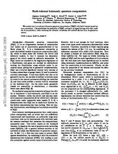
Figure 1. Direct matrix implementation of the FSM from Table I
The structural table can be directly implemented by
2
the PLA structure. This implementation can be achieved by the direct mapping of each row of the structural table into the PLA plans. The direct matrix implementation of the FSM from Table I is presented in Fig 1. It is easy to examine the properties of the obtained FSM. FSM transitions and, consequently, rows of the PLA are defined by products of the small rank. It leads to a low density of the PLA. At the same time, there are some places of high density. Such places correspond to the binary code of the FSM states. III.
SIX MATRIX ARCHITECTURE FOR NANO-PLA
In this chapter, we introduce the Six Matrix (SM) PLA architecture of the FSM oriented on the fault tolerant nano-PLA. We use an example of the FSM defined by Table I. The general structure of the SM PLA architecture is presented in Fig. 2.
(
)
1. Inputs transformation X 1 ! T " P ; 2. Core transformation:
(X
2
) (
)
! P ! T " Q ! #1 ! D ;
3. Outputs transformation: Q ! " 2 . Two additional sets of auxiliary variables are introduced into the SM architecture:
{
P = p1 ,…, pK
} - the set of
output variables of
IPLA (auxiliary input variables of the CPLA);
{
Q = q1 ,…, q M
} - the set of
output variables of
CPLA (auxiliary input variables of the OPLA). While the two transformations PLAs perform combinational functions of the corresponding transformations, the core transformation PLA corresponds to a core FSM that performs the main functions of the initial FSM. A. Inputs
transformation PLA
( ) be a set of input variables that determine
Let X ai
the transitions from state
ai . In our example:
( ) { } ( ) { } ( ) X ( a ) = { x , x } ; X ( a ) = { x , x } ; X ( a ) = !; X ( a ) = {x , x , x } ; X ( a ) = {x } . X a1 = x1 ; X a5 = x4 , x6 ; X a2 = !;
Figure 2. Six Matrix architecture
Let the combinational part of the initial FSM implements the transformation ( X ! T ) " (Y ! D ) , where: •
{
}
X = x1 ,…, x L ; is the set of input variables,
X = X1 ! X 2 , X1 " X 2 = # , •
{
}
Y = y1 ,…, y N ; is the set of output variables,
Y = !1 " ! 2 , !1 # ! 2 = $ ; •
{
variables; •
}
T = t1 ,…,t R ; is the set of present state
{
}
D = d1 ,…, d R ; is the set of the next state
variables. Two main transformations form the SM architecture: the transformation of input variables and the transformation of output variables. Both of the transformations are implemented by corresponding PLAs. As a result, the final SM structure comprises three PLAs: an input transformation PLA (IPLA), a core transformation PLA (CPLA) and an output transformation PLA (OPLA). Transformations performing by the PLAs are the following:
6
5
7
4
1
2
3
3
7
8
8
7
6
The idea of transformation of the original input variables can be formulated as a problem of replacing the set of variables X with a set of new variables P . A number of variables in the set P may be smaller or equal to the maximal number of variables in sets X ( ai ) . In our example: P ! 3 . To optimize the PLA implementation of the input transformation PLA, a specific state assignment may be applied. Let the following state assignment is used: K ( a1 ) = 110; K ( a2 ) = 000; K ( a3 ) = 101;
K ( a4 ) = 010; K ( a5 ) = 011; K ( a6 ) = 100;
K ( a7 ) = 111; K ( a8 ) = 001 Table II illustrates one of possible variants of the replacement of variables X with variables P . TABLE II. REPLACEMENT OF INPUT VARIABLES
am a1 a2 a3 a4 a5 a6 a7 a8
p1 x1 x7 x1 x4 x7 -
p2 x8 x2 x6 x5 x6
p3 x3 -
It is clear from the table that variable x3 may be routed directly to the Core PLA. Namely:
3
{ }
X 2 = x3 , and X1 = X \ X 2 . After minimization, these encoding variables can be expressed as follows:
p1 = t 2 t 3 x1 + t 2 x7 + t 2t 3 x4 ; p2 = t1t 3 x8 + t 2 t 3 x2 + t 1t 3 x6 + t 2 t 3 x5 . Obviously, the above expressions can be directly implemented by a PLA structure having a small area. B. Outputs
transformation PLA
The outputs transformation PLA transforms a set of variables to a subset of output variables ! 2 .
yi is present
Notice that each of the output variables in a number of
J = 10 and:
q1 , q2 , q3 . C. Core
PLA
The core transformation PLA implements the Core FSM, which means the transformation . The Core FSM differs X 2 ! P ! T " Q ! #1 ! D
(
) (
)
from the initial FSM by its inputs and outputs. It uses new P variables instead of input variables X 1 , and new Q variables instead of output variables ! 2 . The transition functions and the next state functions of the core FSM remain the same as in the initial FSM. The core FSM for our example is presented by Table III. TABLE III. STRUCTURAL TABLE OF THE CORE FSM
Y j -sets. In our example (Table I),
Y0 = !; Y1 = { y2 , y5 , y10 };Y2 = { y3 , y4 };Y3 = { y1 , y3 , y4 }; Y4 = { y10 , y11 };Y5 = { y6 , y8 };Y6 = { y1 , y3 };
Y7 = { y9 , y14 };Y8 = { y7 };Y9 = { y6 , y13 };Y10 = { y12 } Each
Y j -set
( )
K Y j of length M , M ! "# log 2 J $% . Let be a minterm of variables q1 , …, qM
(vector)
Bj
may be associated with a binary code
corresponding to
Y j -sets can be variables
( )
K Y j . Consequently, each of the
mapped to the minterm and the output
yi ( i = 1,…, N ) can
of the minterms
be expressed as a sum
B j , ( j = 1,…, J ) . In our example:
y1 = B3 + B6 ; y2 = B1; y3 = B2 + B3 + B6 ; y4 = B2 + B3; y5 = B1; y6 = B5 + B9 ; y7 = B8 ; y8 = B5 ; y9 = B7 ; y10 = B1 + B4 ; y11 = B4 ; y12 = B10 ; y13 = B9 ; y14 = B7 .
The core FSM can be implemented by the PLA structure directly. It is easy to see that the core transformation PLA is a dense matrix. After the minimization, the resulting six-matrix structure for our example looks as shown in Fig. 3.
Obviously, these expressions can be implemented by a PLA structure. The set
!1 consists of all the output variables
produced by single product terms. The remaining output
! 2 . The output variables of ! 2 ! j -sets. In our example, define a set of punctured Y variables form the set
{
}
! 2 = y1 , y3 , y4 , y6 , y10 , y11 , y13 and !1 = Y \ ! 2 . ! Therefore the punctured Y -set corresponding to the 1
! 1 = { y } ."" original Y1 -set equals to Y 10
! j -set is associated with a certain Each" punctured Y code. The number of the coded bits is
{ }
M = log 2 !" Y! j #$ . In our case:
{Y! } = 8 , hence j
each code is represented by a minterm of the variables
The resulting SM scheme built for our example has the total area overhead equals 479 crosspoint. Taking into account that the direct matrix implementation requires 608 crosspoints, we have 22% area reduction by using the proposed SM scheme.
4
The use of the SM synthesis approach in the TMR nano-PLA structure yields area overhead of 1530. The TMR scheme, for the standard direct FSM implementation, gives 1914.
In Table IV, the area overhead for a single PLA having I input crossbars, P product crossbars, O outputs, is calculated according to the following formulae: Sorg = IP + OP;
After applying the four tautology techniques to the SM implementation for our example, we obtain the following values of the area overhead:
STMR = 3IP + 3OP + 9P;
S AO = 1664; S AOO = 984; S AAOO = 1048; S AOOA = 1288. IV.
EXPERIMENTS AND ESTIMATION OF THE PROPOSED SOLUTION
Two main characteristics are commonly used as optimization criteria in synthesis by nano-PLAs, the required area and the required total number of devices. In this section, we show that while known methods require more than 100% additional area and devices, our method requires just about 15% additional area and 120% devices.
S AO = 4IP + 2OP; S AOO = 2IP + 2OP + 2O; S AAOO = 2IP + 2OP + 2P + 20; S AOOA = 2IP + 4OP + 6O. The last two rows of Tables IV and V comprise average overheads for the direct
(W ) SM
(W ) direct
and SM
solutions normalized by the corresponding
overheads required for the direct PLA implementation of the original FSM. TABLE IV. BENCHMARK RESULTS FOR AREA OVERHEAD
Notice that the SM technique has a potential of reducing the additional devices amount by using optimized encoding of auxiliary variables and other optimization techniques. However, to show the potential of our approach, we have used a simple straightforward encoding toward area minimization and without optimizing the number of devices. After decomposing a PLA corresponding to the initial FSM into three interacting matrices, a big number of fault tolerant nano-PLA structures implementing the FSM can be generated. Indeed, each of the three portions of the SM architecture can be implemented by using one of the four tautology schemes [14] or by using the TMR scheme. This provides a significant level of flexibility in searching the optimal solution. In our experiments, we used a set of FSM benchmarks to test the proposed SM approach in various tautology schemes. For this purpose, we decomposed all the benchmarks according to the proposed approach and estimated the required area overhead and the devises overhead, when all three of the SM PLAs were implemented by the same technique, that is: TMR, A-O, A-O-O, A-A-O-O or A-O-O-A architectures. The experiments were performed by using a system EDA tool Abelite [3]. Experimental results for the area and the devises overheads are shown in Tables IV and V respectively. In both of the tables, each benchmark is represented by two rows – the first one corresponds to the direct implementation and the second – to the decomposed (SM) implementation. Columns of the table are: a benchmark name, numbers of inputs, outputs and product terms in the benchmark correspondingly, numbers of devices (Table V), the method of implementation (direct and SM), the overhead for the non fault tolerant FSM implementation, the overhead for the TMR scheme. The last four columns correspond to the four tautology schemes correspondingly.
The results presented in Tables IV and V clearly indicate efficiency of the SM method. As shown in the last two rows of both of the tables, it provides significant reduction of the area overhead without increasing of the number of devises (15% area overhead and 120% additional devices) considerable. The SM has advantages over the conventional direct solution in all the four fault tolerant schemes. The most impressive advantage is achieved for the A-O-O scheme giving more than 50% reduction in the area overhead in comparison with the direct solution. In the case of direct implementation, using fault tolerant schemes A-O and A-O-O-A seems not efficient since the required overhead occurs to be approximately the same as in the TMR scheme. Nevertheless, after applying the proposed SM approach, these schemes A-O and A-O-O-A produce
5
overhead reduction of about 40% and 50% respectively. At the same time, when using the SM approach, the best solutions are provided by the A-A-O and the A-A-O-O schemes, while the A-O and the A-O-O-A schemes still give the overhead close to the TMR SM solution. The benchmark results show that all fault tolerant FSMs implemented according to the SM architecture have the significantly lower area overhead than the same FSMs would they be implemented by conventional fault-tolerant techniques. For one and the same fault-tolerant technique, the proposed method provides the area overhead reduction of about 50%. The SM method requires certain amount of additional devices to be introduced into the resulting scheme. For the majority of the benchmarks, the additional devices overhead does not exceed 10%, which have to be considered as relatively small penalty for achieving the above area reduction. TABLE V. BENCHMARK RESULTS FOR DEVICES OVERHEAD
nano computing structures. 1.
Diagnostics possibility. Since the SM architecture comprises three smaller PLA portions, it may be tested and diagnosed easier than the standard onePLA scheme.
2.
Flexibility. In the SM architecture, each of the component PLAs may be implemented by any of the known fault tolerant technique and the best solutions can be selected for the resulting scheme.
3.
Optimization possibility. The SM architecture provides a possibility of the “area - devices number” trade-off, which may be achieved by optimized encoding of auxiliary variables, states assignments etc.
The obtained results demonstrate the high potential of the presented SM approach and open future research directions.
REFERENCES
V.
CONCLUSIONS
The paper deals with fault tolerance techniques for nanoelectronic PLAs. Tautology based fault masking schemes are used as a base for our study. We have proposed to decompose a combinational part of an FSM into three component PLAs connected in series (SM architecture). The proposed decomposition allows selectively applying various fault tolerant techniques to the components. Our decomposition is performed in such a way that each component PLA has high density, i.e. quite a low percent of the PLA cross points include devices. As a result, such decomposition minimizes the area overhead. The proposed SM decomposition method brings the following benefits, which are significant in synthesis of
[1] Astaf’ev, M., Levin, I., Matrosova, A., Sinelnikov, V. (2002). “Self-Testing Automaton Networks: Their Design in Programmable Logical Matrices”, Automation and Remote Control, 63(10), 16371652. [2] Baranov S., “Logic Synthesis For Control Automata”, Kluwer Academic Publishers, Norwell, MA, USA, Pages: 408, 1994. [3] Baranov, S. “Logic and System Design of Digital Systems”, TTU Press and SiB Publishers, Tallinn, 2008. [4] Chen Y., Jung G. Y., Ohlberg D., Stewart D. R., Jeppesen J. 0., Nielsen K. A., Stoddart J. F. and Williams R. S., “Nanoscale Molecular-switch Crossbar Circuits”, Nanotechnology, vol. 14, pp. 462-468, 2003. [5] Fuchs W. K., Chen C. R., Abraham J. A. “Error Detection in Highly Structured Logic Arrays”, IEEE Journal of Solid-State Circuits, Vol. 22, n. 4, pp. 583-594, August 1987. [6] J. Khakbaz, E. J. McCluskey, “Concurrent Error Detection and Testing for Large PLA's”. IEEE Journal of Solid-State Circuits, Apr 1982, Volume: 29, Issue: 4, pages: 756- 764. [7] Lala, P.K., Tao, D.L. “On fault-tolerant PLA design”, IEEE Proceedings Southeastcon '90, vol.3, 1990, pp. 945-947. [8] Levin I. (1986). “Decompositional Design of Automata Based on PLA with Memory”, Automatic Control and Computer Sciences. [9] Levin, I. (1987) “Hierarchical Model of the Interaction of Microprogrammed Automata”,. Automatic Control and Computer Sciences, 21(3), 67-73, Vol. 20, No. 2, 61-68. [10] Levin I., Karpovsky M., “On-line Self-Checking of Microprogram Control Units”, (1998) 4-th IEEE International On-line Testing Workshop, Capri, Compendium of papers, 153-159. [11] H. Naeimi and A. DeHon, “A Greedy Algorithm for Tolerating crosspoints in Nano PLA design”, Proceedings IEEE International Conference on Field-Programmable Technology, pp. 4956, 2004. [12] Nikolic, K. Sadek, A. Forshaw, M. “Architectures for reliable computing with unreliable nanodevices”. Proceedings of the 2001 1st IEEE Conference on Nanotechnology, 2001, pp. 254-259. [13] Tahoori M. B., D”efect Tolerance in Crossbar Array NanoArchitectures”, In: Emerging Nanotechnologies. Test, Defect Tolerance, and Reliability, Series: Frontiers in Electronic Testing, Vol. 37, M. Tehranipoor, (Ed.). [14] Wenjing Rao, Alex Orailoglu, Ramesh Karri, “Logic Level Fault Tolerance Approaches Targeting Nanoelectronics PLAs”, Design, Automation & Test in Europe Conference & Exhibition, 2007. DATE '07, 2007 pp. 1 – 5. [15] Wenjing Rao, Alex Orailoglu, Ramesh Karri, “Fault Tolerant Approaches to Nanoelectronic Programmable Logic Arrays”, 37th Annual IEEE/IFIP International Conference on Dependable Systems and Networks, 2007. DSN '07, 2007 pp. 216 –224.
6