complete shadow edge contour (in orange) due to the inner doughnut boundary, ... Our approach can recover a doughnut shaped object using cast shadows.
Detecting and Segmenting Un-occluded Items by Actively Casting Shadows Tze K. Koh1,2,3 , Amit Agrawal1 , Ramesh Raskar1 , Steve Morgan3 , Nicholas Miles2 , and Barrie Hayes-Gill3 1
2
Mitsubishi Electric Research Labs (MERL), 201 Broadway, Cambridge MA 02139, USA, [agrawal,raskar]@merl.com, WWW home page: http://www.merl.com/people/agrawal/index.html School of Chemical, Environmental and Mining Engineering, University of Nottingham, UK, [enxtkk,nick.miles]@nottingham.ac.uk 3 School of Electrical and Electronic Engineering, University of Nottingham, UK, [steve.morgan,barrie.hayes-gill]@nottingham.ac.uk
Abstract. We present a simple and practical approach for segmenting un-occluded items in a scene by actively casting shadows. By ’items’, we refer to objects (or part of objects) enclosed by depth edges. Our approach utilizes the fact that under varying illumination, un-occluded items will cast shadows on occluded items or background, but will not be shadowed themselves. We employ an active illumination approach by taking multiple images under different illumination directions, with illumination source close to the camera. Our approach ignores the texture edges in the scene and uses only the shadow and silhouette information to determine the occlusions. We show that such a segmentation does not require the estimation of a depth map or 3D information, which can be cumbersome, expensive and often fails due to the lack of texture and presence of specular objects in the scene. Our approach can handle complex scenes with self-shadows and specularities. Results on several real scenes along with the analysis of failure cases are presented.
1 Introduction Human vision system is extremely efficient at scene analysis. Identifying objects in the scene and grasping them is a mundane task for us. However, designing vision algorithms even for such simple tasks have proven to be notoriously difficult. For example, random 3D ’bin-picking’, where objects are randomly placed in a bin is still an unsolved problem. Commercial systems typically address less taxing robot-guidance tasks, such as picking singulated parts from a moving conveyor belt and employ 2D image processing techniques. Partial occlusion with overlapping parts is a serious problem and it is important to find un-occluded objects. In this paper, we address the problem of identifying un-occluded items in a scene. By ’items’, we refer to objects (or part of them) enclosed by depth edges. Such an approach could serve as a pre-processing stage for several vision tasks, for example, robotic manipulations in factory automation, 3D pose estimation and object recognition. Our motivating application for detecting un-occluded items is to enable a robotmounted vision system to better plan the picking sequence.
Depth Edges Shadow Edges
A
B
A T-junction
B
A Shadow Region 1
B
A
Shadow Un-occluded Region 2 Item
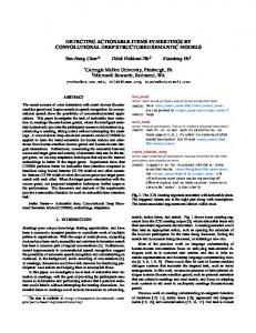
Fig. 1. Segmenting un-occluded items. (Left) Implementation of our active illumination approach using a firewire camera and eight light emitting diodes (LED’s) around it. (Right) A scene with two objects. B is occluded since it contains a shadow edge (orange). Equivalently, B’s shadow region does not contain the complete depth edge contour (green) of B as its depth edges are intersected by shadow edges. However, A’s shadow region contains its complete depth edge contour. Thus, un-occluded items can be obtained by filling in depth edges inside shadow regions.
Although 2D image segmentation approaches can segment an image into semantic regions, in absence of 3D or depth information, these approaches cannot identify occlusion between objects. It is a general belief that once 3D or depth information is obtained, several vision tasks can be simplified. Although past decades have witnessed significant research efforts in this direction, accurate 3D estimation is cumbersome, expensive and usually have limitations (e.g. stereo on non-textured surfaces). Even if the depth map of the scene is available, one would have to do an analysis similar to ours to find un-occluded objects. This is because un-occluded objects may not necessarily be at a smaller distance from the camera as compared to occluded objects. Range segmentation may segment the depth map into regions, but one still needs to determine the occlusions to remove occluded objects. More importantly, we show that such an analysis can be done using depth and shadow edges without obtaining the depth map of the scene. Thus, our approach inherently overcomes the limitations of shape-from-X algorithms. Our approach can easily handle textured and non-textured objects as well as specular objects (to certain extent) as described in Sect. 3. Contributions: We make the following contributions in this paper – We propose an approach to segment un-occluded items in a scene using cast shadows. We describe a simple implementation for this approach using depth and shadow edges. – We analyze practical configurations where our approach works and fails including self-occlusions, mutual occlusions, object with holes and specular objects. – We show how to handle missing depth/shadow edges due to noise and lack of shadow information. 1.1 Related Work 2D/Range Segmentation: Image & range segmentation [1–6] is a well researched area. Although 2D segmentation can segment an image into semantic regions, it cannot provide occlusion information due to the lack of depth information. Even when a depth map of the scene is available, we need to explicitly find occlusions using depth edges. In Sect. 2, we show that depth edges can be directly obtained using active illumination without first computing a depth map. Shape from Silhouettes: These approaches [7–10] attempt to infer 3D shape from silhouettes obtained under different view-points. The computed silhouettes for every
Top View
Depth Edge Concave Edge Convex Edge Shadow Edge
A B Scene
B
A
A Cast Shadows
Depth & Un-occluded Item Shadow Edges
Fig. 2. (Left) Different types of edges [22]. It is well-known that occluding contours alone cannot provide a unique interpretation of the objects in the scene [24, 23]. We therefore find un-occluded items, which are objects or part of objects enclosed within depth edges. (Right) In this scene, A and B could be parts of the same physical object or two different physical objects. Since A cast shadows on B, our approach will identify only A as the un-occluded item.
image along with the camera center of the corresponding camera is used to define a volume assumed to bound the object. The intersection of these volumes known as the visual hull [11] yields a reasonable approximation of the real object. In contrast, we capture images from a single view-point under varying illumination and use the information in cast shadows to segment un-occluded objects. Active Illumination: Several vision approaches use active illumination to simplify the underlying problem. Nayar et al. [12] recover shape of textured and textureless surfaces by projecting an illumination pattern on the scene. Shape from structured light [13, 14] has been an active area of research for 3D capture. Raskar et al. [15] proposed the multi-flash camera (MFC) by attaching four flashes to a conventional digital camera to capture depth edges in a scene. Crispell et al. [16] exploited the depth discontinuity information captured by the MFC for a 3D scanning system which can reconstruct the position and orientation of points located deep inside concavities. The depth discontinuities obtained by the MFC have also been utilized for robust stereo matching [17] and recognition of finger-spelling gestures [18]. Koh et al. [19] use the depth edges obtained using multi-flash imaging [15] for automated particle size analysis with applications in mining and quarrying industry. Our approach also uses a variant of MFC (with 8 flashes, Fig. 1) to extract depth discontinuities, which are then used to segment un-occluded objects. Interpretation of Line Drawings: Our visual system is surprisingly good at perceptual analysis of line drawings and occluding contours into 3D shapes [20]. Labeling line drawing into different types of edges has been proposed by Huffman [21]. Waltz [22] describe a system to provide a precise description of a plausible scene which could give rise to a particular line drawing for polyhedral scenes. Malik [23] proposed schemes for labeling line drawing of scenes containing curved objects under orthographic projection. Marr [24] argued that a given silhouette could be generated by an infinite variety of shapes and analyzed the importance of assumptions about viewed surfaces in our perception of 3D from occluding contours. Our goal is not to interpret occluding contours into 3D shapes, but to label occluding contours corresponding to un-occluded objects in the scene.
2 Segmentation using Information in Cast Shadows In this section, we describe the basic idea of segmenting un-occluded items in a scene. We first assume that complete depth and shadow edges are available, i.e., there are no
Depth Edges
Depth & Shadow Edges
Shadow Regions
Un-occluded Items
Fig. 3. Depth and shadow edges can be obtained using active illumination. (Top Row) The eight input images captured using our setup. (Middle Row) Ratio images obtained by dividing the input images with Imax . Note that the ratio images are texture-free and have shadows according to the corresponding LED direction. (Bottom row) Depth & shadow edges are obtained using ratio images. Note that only the shadow region corresponding to the red crayon contains closed depth edge contours. Thus, filling depth edges inside shadow regions will correctly output the red crayon as the un-occluded item. Matlab source code and input images for this example are included in the supplementary materials.
missing edges. We do a thorough analysis of this ideal case for several practical scenes in Sect. 3. In Sect. 4, we will extend our approach to handle missing edges. As mentioned earlier, depth edges alone cannot provide a unique interpretation for objects in the scene. Thus, our goal is not to interpret depth edges into 3D shapes, but to identify or label those depth edges that possibly correspond to un-occluded objects in the scene. In particular, our approach outputs items enclosed by depth edges (See Fig. 2). In Sect. 3, we show how this is affected by self-shadows, self-occlusions and mutual occlusions. We assume that the scene consists of objects lying on a flat surface and on top of each other, and the view direction is along the vertical direction. Consider a simple scene show in Fig. 1, where A casts shadow on B and B casts shadow on the background. We depict depth edges in green and shadow edges in orange color. Suppose we could segment the boundaries of A and B from the captured intensity images. Then we could easily infer that since region B has a shadow edge, it must be occluded. Thus, all regions that do not have any shadow edges are potential candidates for un-occluded objects. The important question is how to obtain such a segmentation so that the segmentation boundaries correspond to object boundaries or shape edges? Note that any 2D segmentation approach relies on image intensities and thus will respond to texture/reflectance edges. A depth edge may not correspond to a texture edge at the same location in the image (e.g. all objects with same reflectance, Fig. 4) and intensity edges on object surfaces will result in false depth edges. Thus, we need a robust method to find depth edges which can ignore texture edges. Computing Depth Edges: The active illumination method proposed in [15] is an easy way to find depth edges in the scene. In this approach, four flashes are attached close to the main lens of the camera along left, right, top and bottom directions.
Four images, I1 , I2 , I3 , and I4 are captured, each under a different flash illumination. Since shadows will be cast due to object boundaries and not due to reflectance boundaries, depth edges can be extracted using the shadows. To compute depth edges, first a max composite image (Imax ) is obtained by taking the maximum of intensity value at every pixel. Imax will be a shadow-free image. Then, ratio images are calculated as ri = Ii /Imax . Depth edges are obtained by estimating the foreground to shadow transition in each ratio image and combining all the estimates. In our implementation, we capture eight images with different illumination directions using the setup shown in Fig. 1. Fig. 3 shows an example on a scene containing three overlapping crayons. Note that the shadow edges can be similarly obtained by estimating the shadow to foreground/background transition in each ratio image. Segmenting Un-occluded Items: The basic idea in segmenting un-occluded items is to utilize the cast shadows information. If we trace the depth edges in clockwise direction, the cast shadows should always be on the left of the depth edge. In other words, if an object is un-occluded, then cast shadows cannot fall inside the object, or to the right of the depth edge. T-junctions at the intersection of two objects (Fig. 1) can also be handled with this tracing method by always tracing along the rightmost boundary at junctions. In Fig. 1, at the intersection of A and B, the above condition will be satisfied for A but not for B, identifying A as an un-occluded item. Instead of tracing depth edges which might be cumbersome, we propose a simple equivalent implementation using shadow edges. The shadow edges segment the image into regions. For any un-occluded object, the shadow region should contain the entire depth edge contour for that object. For example, in Fig. 1, shadow region 1 contains the entire depth edge contour of object A. However, for occluded objects such as B, the shadow edge cuts through the depth edge. For shadow region 2, the depth edges inside that region do not form a closed contour. Thus, to find un-occluded items, we simply region fill the depth edges inside each shadow region. For occluded objects, since the depth edges inside the shadow regions will not be complete, they will not get filled. In Fig. 3, the shadow edges form five regions as shown in the last row. Only the depth edges in the shadow region corresponding to the red crayon form a closed contour. Thus, the red crayon will be correctly identified as un-occluded item. Supplementary materials include Matlab source code and input images for this example.
3 Practical Configurations In this section, we analyze common scenes which give rise to more complex shadow configurations such as objects with self-shadows, objects with holes and specular objects. We also analyze two failure cases involving self-occlusions and mutual occlusions. Self-shadows: We consider self-shadows as those shadows of an object which fall on the object itself. Fig. 4 shows an example where the part ’R’ of the rabbit shaped object A casts shadow on itself 4 . The self-shadows lead to extra depth and shadow 4
The part ’R’ is a slanted piece whose one side is attached to the object A.
Self-shadows
Extra Edges
A B
Scene
Right Flash Ratio Image
Depth and Shadow Edges
Shadow Region 1
Depth edges inside shadow region 1
Filled Depth Edges: Unoccluded Item
Shadow Regions
Fig. 4. Self-shadows. The scene consists of a rabbit shaped object A on top of another object B. Part ’R’ of object A casts shadow on itself as evident from the ratio image corresponding to the right flash. This leads to extra depth and shadow edges as shown in the third image. If these extra edges do not form closed contours, erroneous shadow regions are not obtained. Note that the shadow region corresponding to the rabbit still contains the closed contour corresponding to the outer boundary of object A.
edges. These extra edges can be ignored by our algorithm if they do not form closed contours, or do not cut through the outer boundary of the object. Note that the shadow edges lead to five shadow regions which would also have been obtained if the selfshadows were not present. By filling in the depth edges inside shadow region 1, we can identify object A as an un-occluded item. In Sect. 3.1, we show that when the extra depth edges due to self-shadows form closed contours with other depth edges, the entire object is not identified as an un-occluded item. Object with Holes: Our algorithm can handle challenging cases of objects with holes. A common scenario is shown in Fig. 5. Although the depth edges are the same in two cases, the cast shadows are different. For two spheres case, the upper sphere will cast shadows on the lower sphere and thus only the upper sphere will be considered as the un-occluded item. For the doughnut case, note that the shadows cast by the inner region does not contain any depth edges, and hence will be ignored. The shadows cast by the outer region contains both depth edge contours. If the un-occluded item is obtained by filling the depth edges inside the outer shadow region as before, the doughnut hole will also get filled. We can remove the holes by ignoring those filled regions that contain a complete shadow edge contour. The inner filled region (in green) contains the complete shadow edge contour (in orange) due to the inner doughnut boundary, and can be removed. Specularities and Specular Objects: Specular highlights on objects are a common problem for vision algorithms as they tend to saturate and are view dependent. In the case of specular highlights, the active illumination approach for finding depth edges results in spurious depth edges [15, 25]. We show that similar to the self-shadowing case above, our approach can ignore the effect of specular highlights if the spurious depth edges due to specularities do not form closed contours. For example, in Fig. 3, the specularities on the green and the red crayon result in spurious depth edges inside
Doughnut
Two Spheres Cast Shadows
Depth & Shadow Edges
Shadow Region
Un-occluded Item
Fig. 5. Object with holes. Our approach can recover a doughnut shaped object using cast shadows information.
the crayons. But since these edges do not intersect the true depth edges and do not form closed regions, they can be ignored while filling in the true depth edges inside shadow regions. Scene
Depth and Shadow Edges
Shadow Regions
Un-occluded Items
Specular Object
Fig. 6. Handling specular objects. Using our method, depth edges for specular objects can also be obtained. If spurious depth edges due to specularities do not form closed contours, specular objects can be handled.
A more general case of a scene having a specular object is shown in Fig. 6. An important point to note is that while specularities may result in spurious depth edges, the true depth edges even for a specular object are obtained by our technique. This is different from other techniques such as stereo/photometric stereo where the estimation is completely incorrect for specular objects. Note that in Fig. 6, the outer depth edges for the specular object are obtained. The shadow edges results in four regions. Once again, by filling in the depth edges in shadow regions, the un-occluded specular object can be recovered. Only the shadow region corresponding to the specular object has closed depth edges, as other objects are shadowed by the specular object.
3.1 Failure Cases Two important failure cases are described below. Self-Occlusions: The first case correspond to self-occlusions such that the depth edges due to self-occlusion form closed regions with outer depth edges of the object. Fig. 7 shows an example. Note that the part of the object which is occluded by the object itself cannot be recovered. Mutual Occlusions: The second failure case correspond to mutual occlusions, where object A occludes object B but is also occluded by the object B at the same time. Fig. 7 shows such a scenario for a scene containing two pipes. For this scene, neither of the two pipes or any part of them will be segmented as an un-occluded item.
Scene
Depth & Shadow Edges
Scene
Shadow Regions Region 3
Depth Edges within Region 3
Depth & Shadow Edges
Un-occluded Item
Filled Region
Shadow Regions
Fig. 7. Failure Cases. (Top row) Self-Occlusions. The scene consist of a single pipe which occludes itself. The shadow edges results in three shadow regions. Only region 3 has closed depth edge contours. However, filling in the depth edges inside region 3 followed by hole removal only recovers the un-occluded part of the object as the un-occluded item, instead of the entire object. (Bottom Row) Mutual Occlusions. The scene consist of two mutually occluding pipes. The shadow edges give rise to five regions. However, none of the shadow regions contain complete depth edge contours as each depth edge is intersected by some shadow edge. Thus, the output will be zero un-occluded items. Scene
Edges
Pseudo-depth Map
Segmented
Un-occluded Items
Fig. 8. Handling missing edges. In a complex scene with several objects, depth and shadow edges may be missing (pointed by white arrows). We first compute the pseudo-depth map of the scene. We then complete the depth edges by segmenting the pseudo-depth map. Each segmented region is then checked for occlusions using shadow information. All regions intersecting with shadow edges are removed to obtain un-occluded items.
4 Handling Missing Depth and Shadow Edges In the previous section, we showed that if we have complete depth and shadow edge information, we can reliably segment un-occluded items in the scene. However, in some cases complete depth/shadow edges are not obtained due to noise, or dark surfaces. If shadow edges are missing, correct shadow regions will not be obtained and we cannot use the previous approach of filling depth edges within the shadow regions. Now we describe an extension to handle such cases. Our approach first tries to complete the depth edges by segmenting the pseudo-depth map [17, 15] of the scene. We find an over-segmentation in this step so that all missing depth edges are accounted for, but this may result in extra regions. We then verify each segmented region for occlusion by checking if any shadow falls in that region. Fig. 8 shows a complex scene with several objects. The extracted depth edges have gaps as shown. A pseudo-depth map of the scene is computed by assigning horizontal/vertical gradients to each depth edge pixel, according to the direction of the light source. The magnitude of the gradient is set proportional to the width of the shadow at that pixel [17]. The gradients at all other pixels are set to zero. The pseudo-depth map
is obtained by integrating the resulting 2D gradient field by solving a Poisson equation. We segment the pseudo-depth map using EDISON [3]. The resulting pseudo-depth map and its segmentation is also shown in Fig. 8. Note that all the missing depth edges are completed but the segmented pseudo-depth map have extra regions. The final step consists of checking each region for occlusions. If we draw a line from any point inside an un-occluded object to a point outside the object, it should intersect a depth edge before intersecting a shadow edge. For an occluded object, since the shadow falls inside the object, such a line may intersect a shadow edge first. For example, in Fig. 1, any line drawn from inside of object A to outside will intersect a depth edge (green) first. However, certain lines drawn from the inside of object B to outside will intersect a shadow edge (red) first. Thus, for each segmented region, we draw lines from inside the region at several different angles. We count the number of intersections with a shadow edge before intersection with a depth edge. If this count is greater than some threshold, the region is declared to be occluded. Fig. 8 shows that all occluded regions were successfully eliminated. The starting point of these lines is taken to be the medial axis of each region to handle general regions with concavities.
5 Discussions Several improvements to our approach are possible. Better region filling approaches could handle cases where only a few pixels are missing in depth or shadow edges. A gradient based analysis could be used to remove spurious depth edges due to specularities [25]. Since depth edges are view dependent, the labeling of scene parts as unoccluded items is also view dependent. Higher level information can be combined for object-based interpretation. Limitations: Our approach share the limitations described in [15] for finding depth edges. This includes dark surfaces/background and detached shadows from the objects due to large baseline between the LED and the camera or thin objects. Our scheme works better on curved objects compared to polyhedral objects. The depth edge at the intersection of polyhedral objects may convert into a concave/convex edge depending on the viewpoint, and thus may not be obtained. Conclusions: We have proposed a simple and practical approach to segment unoccluded items in a scene using cast shadows by analyzing the resulting depth and shadow edges. A depth map of the scene is not required and our approach can handle complex scenes with specularities, specular objects, self-shadows and objects with holes. We showed several real examples using our approach and analyzed the failure cases including self-occlusions and mutual occlusions. To handle missing depth and shadow edges, we propose an extension based on segmenting the scene using pseudodepth map and analyzing each region for occlusions. We believe that our approach could serve as a pre-processing stage for several vision tasks including bin-picking, 3D pose estimation and object recognition.
References 1. Shapiro, L.G., Stockman, G.C.: Computer Vision. Prentice-Hall (2001) 2. Shi, J., Malik, J.: Normalized cuts and image segmentation. IEEE Trans. Pattern Anal. Machine Intell. 22(8) (Aug 2000) 888–905
3. Christoudias, C.M., Georgescu, B., Meer, P.: Synergism in low level vision. In: Proc. Int’l Conf. Pattern Recognition. Volume IV. (2002) 150–155 4. Comaniciu, D., Meer, P.: Mean shift: A robust approach toward feature space analysis. IEEE Trans. Pattern Anal. Machine Intell. 24(5) (2002) 603–619 5. Hoover, A., Jean-Baptiste, G., Jiang, X., Flynn, P., Bunke, H., Goldgof, D., Bowyer, K., Eggert, D., Fitzgibbon, A., Fisher, R.: An experimental comparison of range image segmentation algorithms. IEEE Trans. Pattern Anal. Machine Intell. 18(7) (July 1996) 673–689 6. Yim, C., Bovik, A.: Multiresolution 3-D range segmentation using focus cues. IEEE Trans. Image Processing 7(9) (1998) 1283–1299 7. Matusik, W., Buehler, C., Raskar, R., Gortler, S.J., McMillan, L.: Image-based visual hulls. In: SIGGRAPH. (2000) 369–374 8. Cheung, K.M.G.: Visual hull construction, alignment and refinement for human kinematic modeling, motion tracking and rendering. PhD thesis, CMU (2003) 9. Brand, M., Kang, K., Cooper, D.: Algebraic solution for the visual hull. In: Proc. Conf. Computer Vision and Pattern Recognition. Volume 1. (2004) 30–35 10. Franco, J., Boyer, E.: Exact polyhedral visual hulls. In: Proc. Fourteenth British Machine Vision Conference. (2003) 329–338 11. Laurentini, A.: The visual hull concept for the silhouette-based image understanding. IEEE Trans. Pattern Anal. Machine Intell. 16 (1994) 150–162 12. Nayar, S., Watanabe, M., Noguchi, M.: Real-time focus range sensor. IEEE Trans. Pattern Anal. Machine Intell. 18 (1995) 1186–1198 13. Scharstein, D., Szeliski, R.: High-accuracy stereo depth maps using structured light. In: Proc. Conf. Computer Vision and Pattern Recognition. (2003) 14. Zhang, L., Snavely, N., Curless, B., Seitz, S.M.: Spacetime faces: high resolution capture for modeling and animation. ACM Trans. Graph 23 (2004) 548–558 15. Raskar, R., Tan, K.H., Feris, R., Yu, J., Turk, M.: Non-photorealistic camera: depth edge detection and stylized rendering using multi-flash imaging. ACM Trans. Graph. 23(3) (2004) 679–688 16. Crispell, D., Lanman, D., Sibley, P.G., Zhao, Y., Taubin, G.: Beyond silhouettes: Surface reconstruction using multi-flash photography. In: Third International Symposium on 3D Data Processing, Visualization, and Transmission. (2006) 405–412 17. Feris, R., Raskar, R., Chen, L., Tan, K.H., Turk, M.: Discontinuity preserving stereo with small baseline multi-flash illumination. In: Proc. Int’l Conf. Computer Vision. Volume 1. (2005) 412–419 18. Feris, R., Turk, M., Raskar, R., Tan, K., Ohashi, G.: Exploiting depth discontinuities for vision-based fingerspelling recognition. In: IEEE Workshop on Real-Time Vision for Human-Computer Interaction. (2004) 19. Koh, T.K., Miles, N., Morgan, S., Hayes-Gill, B.: Image segmentation of overlapping particles in automatic size analysis using multi-flash imaging. In: WACV ’07: Proc. Eighth IEEE Workshop on Applications of Computer Vision. (2007) 20. Barrow, H., Tenenbaum, J.: Interpreting line drawings as three-dimensional surfaces. Artificial Intelligence 17 (1981) 75–116 21. Huffman, D.A.: Impossible objects as nonsense sentences. In Melzer, B., Michie, D., eds.: Machine Intelligence. Volume 6. Edinburgh University Press (1971) 295–323 22. Waltz, D.: Understanding line drawings of scenes with shadows. In Winston, P., ed.: The Psychology of Computer Vision. McGraw-Hill (1975) 19–91 23. Malik, J.: Interpreting line drawings of curved objects. Int’l J. Computer Vision 1 (1987) 73–103 24. Marr, D.: Analysis of occluding contour. Technical Report ADA034010, MIT (1976) 25. Feris, R., Raskar, R., Tan, K.H., Turk, M.: Specular reflection reduction with multi-flash imaging. In: SIBGRAPI. (2004) 316–321