S. Abou Chakra is with UIT, Lebanese University, Aabey, Lebanon. M. Grzeskowiak ... K. Wang, A. Diet, S. Abou Chakra, C. Conessa, M. Grzeskowiak, T. Bouaziz, S. Protat, D. Delcroix,. L. Rousseau, G. ..... RFID handbook, fundamentals and.
Detecting range and coupling coefficient tradeoff with a multiple loops reader antenna for small size RFID LF tags K. Wang, A. Diet, S. Abou Chakra, C. Conessa, M. Grzeskowiak, T. Bouaziz, S. Protat, D. Delcroix, L. Rousseau, G. Lissorgues, A. Joisel
Abstract — This paper summarizes some tests with Low Frequency (LF, 125 kHz) RFID tags of two types: Card and Token. These tests were done in order to evaluate the feasibility of an identification/traceability of tags which size is constrained and supposed to be detected inside a delimited volume of 40x40x10 cm3. As the size of the antenna tag is supposed to be very small, we improve the detection range and volume of definition by designing different reader antennas. Reader antennas presented are of two types whether they are based on single (SL) or multiple loops (ML). Detection range was evaluated for planar antennas (3 SL and one ML). Volume of definition for the detection was estimated by designing two-level prototypes of ML antennas. Results are discussed about the optimization possibility of detection range and volume thanks to ML.
I. SIZE-CONSTRAINED RFID TAGS TRACEABILITY
R
Frequency Identification (RFID) is currently a well-known concept for traceability in the context of logistic applications [1][2]. However, the technical RF link is to be adapted to the realization constraints such as range, tag size and ergonomic use of the identification process (speed, reliability, contactless or proximity, lifetime…) [3]. In this paper we focus on hand-sized devices traceability, where the RFID tag fixing method is not invasive. Our application is to identify each small devices (metallic or not) along the chain, faster than an optical control and contactless. As each device is used by humans, the RFID tag should not lower its ergonomy. Consequently, one of the major challenges is to minimize the size of the tag antenna, and so reduce the effective area for the induced flux. This will lower the detecting range. Moreover, the range of the control operation needs not to be greater than 10 cm but the volume of control is more important in order to provide a multiple RFID detection of tags at the same time. We target an automatized traceability for several tags in a volume whose basis is defined by an area of 0.4x0.4 m². Consequently, the detection should be higher than several ADIO
Manuscript received July, 21st 2012. K. Wang, A. Diet, C. Conessa, A. Joisel are with L2S-DRE UMR8506. Supelec, plateau du Moulon F-9192 Gif Sur Yvette, France. S. Abou Chakra is with UIT, Lebanese University, Aabey, Lebanon. M. Grzeskowiak, T. Bouaziz, S. Protat, D. Delcroix, L. Rousseau, G. Lissorgues are with ESYCOM EA2552, Cité Descartes, Noisy le Grand, Marne la Vallée, France.
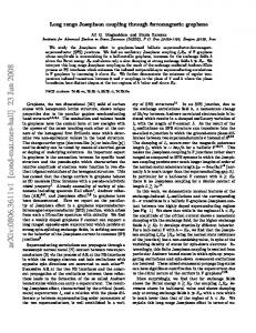
centimeters to provide contactless identification. As devices will be highly mobile and should be as cheap as possible with an important lifetime, we focus on passive R/W tags at low frequency (LF), without battery. Two standard frequencies are highlighted: 125 kHz and 13.56 MHz. These tags are based on inductive coupling and need the design of magnetic antennas (loops based) [2][3][4]. As the size of the tag antenna is a constraint, the first challenge is to optimize the reader antenna for the detection and identification of small tags in the considered volume range (0.4x0.4x0.1 m3). In this paper we discuss and present some antennas for the reader and show a possible detection over a wide surface at a range that can reach 10 cm for small tags. We use the Netronix RFID reader with the H1M005 RFID 125 kHz module, as seen in Figure 1. Two types of tags were considered for that study, as reported in Figure 1. These tags are a Card type, with an area of 7x5=35 cm², and a Token type, with an area π*(1.5)² = 7.07 cm². The ratio of these areas (for the flux) is around 4.95. The card type is used in all the paper for performances comparison, because our application will be to fix tags which size is of the token type. In Figure 1, the RFID reader shows the possibility to connect an external antenna External Reader Antenna
DY
DX
Token TAG (r = 1.5 cm)
Card TAG (7x5cm²)
Figure 1: (Top) Netronix reader with its antenna connector (external) and the definition of DX, DY. (Bottom) Card and Token tags.
In part II, considerations about loop antennas flux are discussed. In part III, different external antennas are considered and designed. Detection Range for the Card and Token types tags are evaluated with these different external antennas. The deviation from the reader antenna center is reported by DX and DY in cm, as illustrated in Figure 1. As the antennas present symmetry axes, DX and DY will be varied from the center (0,0) towards a positive deviation. This is, in reality, only a quarter of the surface that is tested. Finally, two prototypes of two-levels antennas dedicated to a volume control (10 cm height) are tested. These antennas seem highly different from the others because the tags detection is tested between the two levels of the structure. The two types of tags (Card and Token types) are, in that study, tested for (i) range detection with the four different external reader antennas (small, medium, wide and ML1); and (ii) tested for volume detection with the two different Multiple loops antennas (ML2 and ML3).
The three cases reported illustrate different hypothesis that can simplify, or not, the calculus of the coefficient k. Case A is the classical case where both antennas are in the same range of dimensions. Case B is the case of single loop antenna induction when there is a high difference of size. This is the case when it is not possible to consider the magnetic radiated field to be at its maximum strength at the center of the wider loop. Case C is the combination of case A and case B. In case C, the Neumann formula: equ. (1), is difficult to evaluate analytically due to the complexity of the circulation vector expression. In [5], the “k coefficient” can be numerically studied by (2), where R is the distance between the two loops, with the assumption that the centers are aligned (r1 and r2 are the radius of the two loops). This is right for case A configuration. r1r2 k 2 2 R max r1 , r2
II. LOOP ANTENNAS FOR RFID LOW FREQUENCY RF LINK Loops are magnetic antennas used for inductive coupling in LF RFID applications. The design of antennas adapted to these applications in terms of range and area of detection is based on the well-known magnetism theory. As developed in [2][3][4], the reader antenna “1” is geometrically linked to the tag antenna “2” by the “k coefficient” as indicated by equation (1).
Γ1
"k" for 4 cm tag antenna radius
d²l1 d²l2 r1 r2 Γ2
1 to 10 cm reader antenna radius 0.8
(1)
Herein, we will consider three cases whether the antennas “1” and “2” have an effective area in the same range (i.e. a radius in the same range for circular loops) or not and if there is a multiple loop configuration, as seen in figure 2.
0.6 0.4 0.2 0
0
1
2
3
4
5 distance in cm
6
7
8
9
10
"k" for 1.5 cm tag antenna radius
Case C
Case A
0.5 1 to 10 cm reader antenna radius 0.4
i1 i2
k coefficient
i2
Case B
(2)
1
i1
2
This formula is used to evaluate the k coefficient with our two tags types. As reported in figure 3, the “k coefficient” is optimum until a distance of “r.√2” (r is the radius) but highly decreases after this range limit [6]. As our tag size has to be minimal (size constraint) and in order to improve the detection range we target to design an antenna that maintains the value of “k” as constant as possible inside a limited volume, and until a range limit targeted at 10 cm.
k coefficient
k
dl1 dl2 r12 Γ1 Γ 2
3
0.3 0.2 0.1
i1 i2
0
0
1
2
3
4
5 distance in cm
6
7
8
9
10
Figure 3 : “k” with equ. (2), for different tags antennas size (case A)
Figure 2: Three cases of coupling (A, B, C)
As we target the detection over a volume of 40x40x10 cm3 with a small tag which dimension is in the range of the token tag type, the k coefficient should be evaluated for case B
coupling. Following that idea, we compute the mutual inductance for a small circular loop (radius of 1cm) with a rectangular wide loop 40x40 cm². As the coupling is a reciprocal property, we evaluate the flux over a wide rectangular loop (the reader antenna) thanks to cartesian coordinates of the magnetic field generated by a small circular loop (the tag). This calculus was computed numerically with the complete expression of the magnetic field of equation (3) and (4). Figure 4 illustrates the orientation of the magnetic circular loop and the resulting mutual inductance at different distance (X0, from 1 to 5cm) in function of the center deviation or misalignment.
These results will be highlighted by the tests and measurements in the following section. We should also emphasize that, in RFID, there is two major factors for detection: the coupling and the supplying. As coupling is based on “k”, a flux is generated by the reader antenna and the variation of (derivative) a partial integrated flux φ over the effective height/area induces the voltage at the antenna port, loaded by the RFID chip as given in (4).
1 2 M 12
Z
. dS2
1 2
e1 -
i1 12 t
(4)
Y
i1
X0
X
i2 Misalignement (Deviation)
Mutual inductance, in H, for a single spire (radius = 1 cm) and a rectangular loop (0.4x0.4 cm²) -9 in function of the center misalignement, at different distance x 10 10
1 cm 1.5 cm 2 cm 2.5 cm 3 cm 3.5 cm 4 cm 4.5 cm 5 cm
8
Mutual inductance in Henry
B
1 2 surface"2"
6
4
The internal antenna of the reader can be disconnected and we measured an inductance of 1 mH. As the driving current is around 40 mA, the flux without coupling is about 4e-5 Wb. If the induced voltage “e” is sufficient to drive the chip with the minimal supply current, the tag can be powered-on and can respond by load modulating the reader RF signals. State of the art RFID tags at this frequency (125 kHz) need an effective voltage in the range of V0_rms = 3 Vrms in order to power-on the chip. If we generate a magnetic field Hrms thanks to our loops antennas (N turns and an area of A m²), we have the relation of equation (5):
B.n dS
B0 cos ω0 t cos θ S
2
e MAX rms
S B0 ω0 sin ω0 t cos θ t S ω0 Brms NA ω0 μ H rms h eff H rms
e-
(5)
0
-2
-4
0
0.05
0.1
0.15
0.2
0.25
Misalignement (deviation) between the center of the loops, in meters
Figure 4 : Coupling between a circular loop and a rectangular wide loop at different distance (X0) and for different deviation.
B1 2 x, y,z
μ 0 i1 r12 2cos θ u r sin θ u θ 3/2 4 x² y² z²
III. RFID READER ANTENNA DESIGNS AND TESTS Different external antennas were designed. We differentiate the Single Loop Antenna structure (SL) and the Multiple Loops Structure (ML). We differentiate also planar structure for range detection and two-levels structures, delimiting a volume of the targeted area with the 10 cm height.
with u r cos cos θ u x cos sin θ u y sin u z u θ cos θ u y sin θ u x θ tan -1 y x tan -1 y
x² y² z²
Analytical expressions of loop antennas are mainly based on statistical approximation and a lot of semi-empirical equations exist for the design of antennas once a basic shape is chosen. For the design of more complex shapes, for example multiple loops, an electromagnetic calculator, dedicated to LF, is needed.
(3)
In section A and B, we evaluate the range of detection until the limit of 10 cm for the following planar structures: SL small (part A), SL medium (part A) and SL wide (section
B), and one ML antenna which size is compared to the SL wide (section B). In section C, ML2 and ML3 are “twolevel” antennas designed over the targeted detection volume (0.4x0.4 m² x 10 cm). For these two latters, the range detection means nothing, and we only report the area of correct detection. A) Single Loop antennas range (SL small and SL medium)
that the SL medium antenna is a best choice at first glance. We will now introduce the detection over a wider area. B) Wide SL/ML Antennas range (SL wide/ML1) In order to detect the tags over an area of 0.4x0.4 cm², we designed a wider SLA (see figure 7, bottom) and a one-level MLA (see figure 7, top) which is a wide loop including two medium loops in the same plane.
Figure 5 : SL small (left) and SL medium (right)
Figure 3 presents two of the SL planar antenna, which size is in the range of the two tags (Card and Token). They have radii of 1.2 cm and 2.4 cm, and present respectively an inductance of 1.008 mH and 1.01 mH. When connected to the NETRONIX RFID reader with the H1M module, they are driven by a current of 42 mA and 42.3 mA respectively. We can consider that the total flux generated is constant for these two antennas. The areas of the two antennas are consequently 4.5 cm² and 18.1 cm². Figure 6 shows the range limit of the two tag types when using these two antennas. A clipping at 10 cm is done on the scale for comparison between the card and the token tags.
DY from center
0
2
4 6 DX from center
8
0
10
2
8
4
6
6
4
8
2
0
2
4 6 DX from center
8
10
0
6 4 4 6
2
Card Tag range with medium SL antenna 0
10
DY from center
4 6
8
2
8
2
0
2
4 6 DX from center
8
10 8
4
6
6
4
8
2
0
2
4 6 DX from center
The wide SL is 20x30 cm² (600 cm²) with an inductance of 1.009 mH, and is driven by a current of 41 mA. The ML1 has an external loop of 30x40 cm² (area 1200 cm²) and includes two medium loops of 12x12 cm² (area 144 cm²). The different loops are constituted by the same number of turns which is in the range of 50. ML1 inductance is 1 mH, and its driving current is of 43 mA.
0
2
10
8
10
Wide loop is 30x40 cm²
Figure 7 : ML1 (top) and wide SL (bottom)
Card Tag range with wide 20x30 SL antenna 0
Token Tag range with medium SL antenna 0
DY from center
DY from center
6 4
10
30 cm
Token Tag range with wide 20x30 SL antenna 0
10 9 8
5
8
5
7 6
10
5 4
15
10 9
7 DY from center
8
2
8
Token Tag range with small SL antenna 0
10
20 cm
DY from center
Card Tag range with small SL antenna 0
Small loops are 12x12 cm²
6
10
5 4
15
0
Figure 6 : Range limit for the two tags and the two SL (small/med.)
3 2
20
3 2
20
1
We notice that increasing the reader antenna size improves the range limit for the both tags types. We are in a coupling case of “type A”, as presented in the first part of this paper. The token tag, which dimension is close to the SL small reader antenna size, is best supplied by the SL medium flux unless its “k coefficient” is lower. The reason is that the value of k decreases more slowly with the distance. It results
25
0
5 10 DX from center
15
0
1 25
0
5 10 DX from center
15
0
Figure 8 : SL wide range limit (2cm steps)
Figure 8 shows the SL wide antenna range limit (clipped at 10 cm), for the two types of tags. The difference in the effective area for the two types of tags reduces the induced flux φ, and so the range limit because of the supplying
reduction. We notice, for the token tag, that the flux is slightly low at the center of the reader antenna (DX and DY near to 0). This results in a decrease of the range limit on the center axis. Card Tag range with ML1 wide SL antenna 10 0
Token Tag range with ML1 wide SL antenna 0
9
4.5
8
5
4
5
10
5
4
15
3.5
DY from center
DY from center
7
6
3
10
2.5
2
15
3
2
20
1.5
1
20
1
25
0
10 DX from center
20
0
5
In that part, we designed two levels ML antennas, ML2 and ML3 which are based on a serialization of loops. The two levels are due to the fact that we want tags detection inside a limited volume. The top and bottom faces are the two level planes of the antennas. ML2 and ML3 are the two tested prototypes and present the same external dimensions over the different faces: 30x40 cm². ML2 is a combination of a wide loop (23 turns) and 4 medium loops (10x10 cm², 15 turns) and present an inductance of 0.97 mH (40 mA driving current). ML3 is composed of 4 medium loops (10x10 cm², 20 turns) on each side (8 loops). Its inductance is 1.015 mH (41.5 mA driving current). Photos and results are presented in figures 10 and 11 in terms of the volume allowing possible tag detection.
0.5
25
0
5 10 15 DX from center
20
0
Figure 9: ML1 range limit (4cm/2cm steps)
Figure 9 reports the range limit (5 cm is the maximum for the token tag) for the two tags with the ML1 reader antenna. We clearly see that the best positions for the token tag (i.e. when reducing the effective area of the tag) are not at the center but near the medium loops included in the single loop. At such distance (5cm) and for the token tag which size is very small by comparison, we consider abusively (and empirically) for the discussion that the total coefficient k results from the sum and interaction of partial coefficients with the medium and wide loops. Let us wtrite: k = kmedium + kwide + K, where K is the interaction between the two coupling (tag with medium loop / tag with wide loop). Using (2), we have kmedium ≈ 0.05 and kwide ≈ 0.01. At 5 cm, these values are the closest (worst case for the discussion), and we can suppose that, at a lower distance, kmedium is much higher than kwide. These observations are in good agreement with the theoretical simulation reported in figure 4 because wider loops imply the optimal area of coupling to be close to the current circulating. “Case C” coupling is an alternative to improve “case B” by concentrating on localized area (the small loops) the coupling phenomenon. This drives us to consider that the local degree of geometrical similarity between the tag antenna and the reader antenna is the key to improve the detection of small tags. This can counter balance the density reduction of the flux due to the area of the reader antenna.
Figure 10 : ML2 volume of detection for Card and Token tags
In the following section, we propose to verify experimentally that an increase in k (or in a local k) can compensate for the reduction of the induced flux due to the size of the reader antenna adapted to our application. C) Two-Levels Multiple loops antennas (ML2 and ML3)
Figure 11 : ML3 volume of detection for Card and Token tags
In Figure 10, we can see that the volume of detection is localized near the loops. A maximum of 3 cm is reached for the Card tags due to a flux reduction over the total area. The Token tag is only detected at the proximity of the medium loops. If the bottom face has been made with a single loop, the Card tag should have been detected more efficiently because the structure would have been constituted of Helmholtz coils. In Figure 11, the resulting detection volume reveals the directivity of the flux induced by the different loops from one face to another. These local kinds of Helmholtz coils generate a sufficient flux for the tags to be powered-on. As the local k coefficient is higher, the division of the flux between these 4 sub-volumes can be counterbalanced in our case. With ML3, we can illustrate the hypothesis of the local k coefficient and provide a space discretization of the tags control which can help in the detection of multiple tags. In order to analyze the detection results, we simulate the H field distribution inside ML2 and ML3. Figure 12 plots the maximum field values for single turn ML structures, that is to say ML20 and ML30.
IV. CONCLUSION In that paper, we discussed the detection of given tags of types “Card” and “Token” within a limited volume. Range evaluation of this detection was measured with 4 planar antennas: 3 SL and 1 ML. Measurements show that it is possible to increase the range by increasing the area of the reader antenna if its size is in the same order as the tag antenna size (tests with small and medium SL). When the reader antenna is wide, in order to fulfill the targeted detection volume, the coupling coefficient must be considered carefully in function of the distance. Tests with wide SL and ML1 show, for our application, that the degree of geometrical similarity (“local k coefficient”) can compensate a decrease of the flux density. Finally, detection was tested with two prototypes of two-levels antenna (two planes), based on ML structures. These detection tests show that the token tag needs preferentially a high k coefficient, as it is the case for ML3. Simulations of the H field distribution inside ML2 and ML3 structures (simplified as ML20 and ML30) Confirm the volume of detection measurements. To conclude ML are a solution for optimizing the detection, in a given volume, of small RFID LF tags if their (small) size is a constraint. REFERENCES
Figure 12 : Hz filed for ML20 (top) and ML30 (bottom)
As we can see in figure 12, there is a correlation between the value of H field (Hz is the component normal to the planes) and the volume detection. In ML20 the wide loop does not contribute enough to maintain the H field on the normal axis (z). In ML30 simulation, we clearly see that the direction of H is helpful for inducing sufficient voltage in antennas tags whose structures are horizontal loops. The simulation gives a Hz field distribution whose RMS value is two times higher for ML30 than for ML20, and vertically directed. As the ML3 antennas is constituted by 8 times 20 turns 0.01 m² squared loops (0.1x0.1), we compute the effective height heff_1 of 2 loops at each side of the detection volume, that gives around heff_1 = 40 cm.
[1] D. Paret. Identification Radio-Fréquences et Cartes à puce sans contact. Dunod, Paris, 2000. [2] K. Finkenzeller. RFID handbook, fundamentals and applications in contactless smart cards and identifications. 2nd ed., John Wiley and Sons, 2003. [3] S. Barbu. Conception et réalisation d'un système de métrologie RF pour les systèmes d'identification sans contact à 13,56 MHz. Thèse de Doctorat, 2005-313, Université de Marne la Vallée, 2005. [4] C. Balanis. Antenna theory. 2nd ed., John Wiley and Sons, 1997. [5] U. Azad, H. C. Jing, Y. E. Wang. Link budget and capacity performance of inductively coupled resonant loops. IEEE transactions on antennas and propagation, May 2012, pp 2453-2461. [6] Microchip Applications Notes (AN) n°680, passive RFID basics, and n°710, Antenna circuit design for RFID applications. Microchip technology Inc., 2003.