Detection of Ships Using Cross-Correlation of Split-Look SAR Images Masato Iehara1, Kazuo Ouchi2, Isao Takami3, Koichi Morimura1, and Shintaro Kumano 1 1
Takasago Research and Development Center, Mitsubishi Heavy Industries, Ltd. Niihama2-1-1, Arai-chou, Takasago, Hyogo, Japan Tel: +81-794-45-6752, Fax: +81-794-45-6088 Email:
[email protected],
[email protected],
[email protected] 2 Department of Environmental Systems Engineering, Kochi University of Technology Tel: +81-887-57-2509, Fax: +81-887-57-2520, Email:
[email protected] 3 Nagoya Research and Development Center, Mitsubishi Heavy Industries, Ltd. 1-Takamichi, Iwatsuka-chou Nakamura-ku Nagoya, Aichi, Japan Tel: +81-52-412-7942, Fax: +81-52-412-8143, Email:
[email protected]
Abstract- One of the main problems in ship detection is the presence of sea clutter inherent to coherent imagery. A traditional approach to differentiate a target imbedded in noise is to utilize the statistical property of the clutter with some success. In this paper, we propose a new technique of ship detection based on cross-correlating split-look SAR images. If the inter-look images consist of the correlated images of a ship and clutter, the degree of mutual correlation increases, and from the difference in correlation, the ship can be identified. Applying the present method to RADARSAT (Standard 1) images, we have found the minimum detectable size of ships is 62.6m. The SAR data used in this application were acquired under fairly calm sea states, such that the ships can be identified by the naked eye. Thus, the method has not been tested in an extreme limit of high sea states, and remains as a further study.
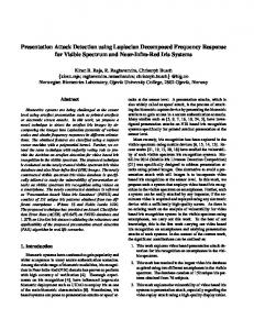
I. INTRODUCTION In ship detection for SAR images, the method that utilizes the deference of pixel intensity between ship and sea clutter is often used. In CFAR[1] technique, the histogram of the region of interest is computed at first. Then, a distribution function (ex. K-distribution) which fits the histogram is calculated to determine a threshold. Finally, pixels which intensity are larger than the threshold are extracted as a part of ship. (Fig.1) In a condition of a heavy sea state, however, these methods that utilize the deference of pixel intensities are not efficient. When a sea state is heavy, pixel intensity of sea clutter grows up and is almost equivalent to pixel intensity of a ship. Therefore, any threshold is not effective for ship detection. A motion of a ship makes the detection process difficult additionally. When a ship is moving, pixel intensity of the ship is degraded because of a blur. Then the effective threshold cannot be determined. In this paper, we introduce a new ship detection technique that utilizes the correlation between split-look SAR images. Sea Clutter 3500
II. BASIC THEORY OF THE NEW SHIP DETECTION TECHNIQUE A. Split-Look Images Dividing the antenna beam into some sub-apertures, and processing these sub-apertures individually, we can obtain split-look images that do not overlap each other. The reference function for processing is set to have different center frequency and bandwidth. In other word, split-look images have small time lag for identical area. SAR
Antenna Beam
Look 1 Look 2 Sea
Threshold Ship
3500
3000
3000
2500
2500
2000
2000
1500
1500
1000
1000
500
SAR Image
scattering object. It is assumed that sea surface consists of small wave and each wave is independent from others. Therefore, there no correlation each other. On the other hand, a ship is larger than image resolution, then correlation between split-look images is large. The advantage of this method is that it is possible to detect a ship without using the pixel intensities. We applied the new technique to a RADARSAT image (Standard mode, 30m resolution), and we confirmed the minimum detectable size of ships is 62.6m.
500
0
0 0
50
100
150
200
250
0
Histogram
50
100
150
200
250
Result
Experimental data K-distribution
Fig.1. CFAR Ship detection method The degree of the correlation is determined by the size of the
0-7803-7031-7/01/$10.00 (C) 2001 IEEE
Look 1 image Look 2 image Fig. 2. Split-look images generated from each sub aperture
1807 0-7803-7033-3/01/$10.00 (C) 2001 IEEE
A peak appears.
uncorrelated Look 1
2D CCF
Look 2
Fig. 3. Correlation of sea clutter Look 1 correlated Look 1
Look 2
Fig. 4. Correlation of a stationary ship correlated Look 1
Look 2
Fig. 7. 2D-CCF for an area which contain a ship
Look 2
Fig. 5. Correlation of a moving ship Pixel intensity of SAR image is a result of interference of all the scattering objects inside the pixel. Because sea surface consists of objects which are smaller than a pixel size, and the number of scattering objects is much enough, intensity of a pixel is treated as random. Therefor, there is no correlation between split-look images (Fig. 3). On the other hand, a ship is larger than image resolution. Therefor, the image pattern of a ship in each split-look images is deterministic, and there is a large correlation between splitlook images (Fig. 4). Even if a ship is moving, there is large correlation despite of blurring (Fig. 5). The basic idea of this technique is utilizing the difference of temporal/spatial correlation of SAR images.
C. Processing Flow The processing flow of ship detection is shown below 1) Generate split-look images from SAR raw data. 2) Extract sub-window from each split-look images. 3) Compute the 2D-CCF between split-look images. 4) If the 2D-CCF has a peak, the sub-window is judged to contain a ship. 5) Process the entire image by moving the sub-window to the next area. III. RESULTS We applied this method for a RADARSAT image in order to confirm the performance. The specification of this image is shown in Table 1. The full scene is shown in Fig.8. We select two target areas for processing.
B. Cross Correlation between Split-Look Images To measure the degree of the correlation, we adopted a twodimensional cross correlation function (2D-CCF), which represents a degree of similarity between two images. When the split-look images are f1(X,Y) and f2(X,Y), 2D-CCF is defined thus. CCF( x, y ) = ∫∫ f 1 ( X , Y ) f 2 ( X + x, Y + y )dXdY
Table 1. Specification of the RADARSAT image Oct. 29, 1998 Acquisition date 21:05(GMT) Area Kumano-Sea(Japan) Beam Mode Standard 1 Orbit Descending Nominal Resolution 30m Pixel Size 8m
Area 2
When there is no correlation between Look 1 image and Look 2 image, 2D-CCF is flat because it is almost same value for entire (x,y). On the other hand, 2D-CCF has a strong peak when the area contains objects that have large correlation. We can judge the existence of a ship by measuring a height of the peak. The position of the peak is related the velocity of the ship. When the ship is moving, the peak is in the position (∆x,∆y) which indicates the distance of the ship’s motion between two images.
Range direction
Area 1
Flat 2D CCF RADARSAT Raw Data (C)CSA1998, distributed by RSI & RESTEC
Look 1
Look 2
Fig 8. RADARSAT Image (Full scene)
Fig. 6. 2D-CCF for an area which consists of sea clutter
1808 0-7803-7033-3/01/$10.00 (C) 2001 IEEE
Azimuth direction
Fig. 9. Area 1
Fig. 10. Area 2
A. Area 1 (Identified Ship) The ship shown in Fig.11 was cruising in this area. The name of this ship is “Tenyo-maru”, the training ship of National Fishery University. The length of the ship is 62.6m, the width is 10.4m the gross tonnage is 1,202 t. We selected this area to examine the basic performance of this method. Fig. 12 shows the result for this area. The detected region is indicated as red pixels, which are superimposed over the SAR image. We confirmed that the position of this ship agrees with the position reported in the JERS-1 Symposium [3]. However, the estimated sea state by JWA (Japan Weather Association) of the area at 3 hours before the imagery accession was not so heavy. Significant wave height was 0.9m, wind speed was 3m/s. Therefor, the advantage of this method, the detectable performance in the heavy sea clutter, has not been confirmed. B. Area 2 (Unidentified Ship) Fig. 13 shows the result for this area. The detected regions (candidate for ship) are considered to be ships because of their wakes. We have no ground truth for this area. We interpreted one of the detected ships in detail (Fig.14). The length of the ship is approximately 50m.
Fig. 11. Tenyo-Maru
Fig. 13. Result (Area 1)
Approximately 50m
Wake Kelvin wake Fig. 14. The interpretation of the detected ship IV. CONCLUTION We introduced a new ship detection technique using cross correlation of split-look images. The advantage of this method is the performance in the heavy sea clutter because of independence on the deference of pixel intensities between ship and sea clutter. As a result for an identified ship in RADARSAT images (Standard mode, 30m resolution), we confirmed that the minimum detectable size of ship is 62.6m. Additionally, an unidentified ship which length is approximately 50m is detected. DATA PROOERTY AND IMAGERY PRODUCTION In this paper, Canadian Space Agency (CSA) is the owner of all signal data from RADARSAT. Mitsubishi Heavy Industries (MHI) purchased the data under the contract of the Remote Sensing Technology Center of Japan (RESTEC). All imageries from the satellite are originally processed by MHI.
RADARSAT Raw Data (C)CSA1998, distributed by RSI & RESTEC
Fig. 12. Result (Area 1)
RADARSAT Raw Data (C)CSA1998, distributed by RSI & RESTEC
REFERENCES [1] Chris Oliver, Shaun Quegan “Understanding Synthetic Aperture Radar Images”, Artech House, 1998. [2] Kourti, N., Shepherd, I., Verborgh, J, “Fishing Boat Detection by Using SAR Imagery (oral presentation)”, Ship Detection in Coastal Waters Workshop, May 2000 [3] Hideo Tameishi, “Development of ship detection techniques in Japan (oral presentation)”, JERS-1 Symposium, May 1999.
1809 0-7803-7033-3/01/$10.00 (C) 2001 IEEE