Deterministic optical quantum logic with multiple high-dimensional degrees of freedom in a single photon Poolad Imany,1,2,†,* Jose A. Jaramillo-Villegas, 1,2,4,† Joseph M. Lukens,5 Ogaga D. Odele,1,2 Daniel E. Leaird,1,2 Minghao Qi,1,3 Andrew M. Weiner1,2,3 1
School of Electrical and Computer Engineering, Purdue University, West Lafayette, IN 47907, USA 2 Purdue Quantum Center, Purdue University, West Lafayette, IN 47907, USA 3 Birck Nanotechnology Center, Purdue University, West Lafayette, IN 47907, USA 4 Facultad de Ingenierías, Universidad Tecnológica de Pereira, Pereira, RI 660003, Colombia 5 Quantum Information Science Group, Oak Ridge National Laboratory, Oak Ridge, TN 37831, USA † These authors contributed equally to this work. * Corresponding author:
[email protected]
abstract-Quantum computation promises a dramatic speedup in many important algorithms, due to its ability to process information in superposition states of quantum bits (qubits)1. Amongst the myriad quantum systems suitable for information processing, photons have the critical advantage of extremely low decoherence, with minimal interaction with their surrounding environment2. This isolation, however, has the downside of also making photon-photon interactions for two-qubit gates difficult and, with linear optics, inherently probabilistic. Such a situation poses a formidable roadblock for photonics in scaling up quantum computing. An intriguing answer to this problem is to encode multiple qubits in a single photon, by making use of different degrees of freedom3,4. While this solution ultimately suffers from exponential resource scaling5, it enables deterministic twoqubit gates and thus offers significant encoding potential in the current generation of quantum circuits. So far, though, experiments in this paradigm have utilized two-dimensional encoding per each degree of freedom, thus failing to exploit the full information capacity of single photons. Qudits—high-dimensional units of quantum information—can be encoded in photonic time and frequency degrees of freedom using on-chip sources like microresonators, which can easily expand the Hilbert space in a scalable way. Here, we demonstrate the first high-dimensional, singlephoton two-qudit gates in time and frequency bins. By exploiting fast optical switching, we realize the cyclic shift operation (generalized X gate) for three time bins, obtaining a computational basis fidelity of 0.996 ± 0.001 and confirming coherence through an interference measurement. By incorporating the frequency-bin degree of freedom as well, via heralded single photons from an on-chip microring resonator, we build on this X gate and implement
the two-qudit controlled increment (CINC) and modulo sum (SUM) gates—either of which are sufficient, along with single-qudit operations, for universal quantum computing6. Our scheme thus shows the potential of deterministic optical quantum computing in high-dimensional Hilbert spaces for practical and compact quantum information processing. Quantum algorithms such as Deutsch-Jozsa7, Shor's factoring8 and Grover's search9 show the power of quantum computation in solving exponentially hard problems in polynomial time. Moreover, quantum computation promises to enable the simulation of complex quantum mechanical systems which are impossible to realize with our current computing infrastructure10. Quantum gates have been demonstrated in multiple platforms such as superconductors11, ion traps12, and different degrees of freedom in photons such as polarization13, orbital angular momentum14, time15, and frequency16. Compared to other platforms, optical states have the advantages of low decoherence and suitability for long-distance communications, but two-qubit gates are probabilistic with standard linear optics and photon counting17(Fig. 1b). To overcome this issue, encoding qubits in different degrees of freedom (DoFs) in a single photon has been demonstrated, where each DoF carries one qubit and, now, interactions between different qubits can be made deterministic3,4. Even though in this case two and three-qubit operations can be executed with unity success probability, each DoF contains only one qubit, and the number of a photon's DoFs are limited; thus the size of the Hilbert space in which these deterministic transformations can happen is fairly moderate (e.g., an eight-dimensional Hilbert space has been demonstrated by encoding three qubits in three different DoFs of a single photon4). In this letter, we take advantage of the high dimensionality in two particular DoFs of a single photon—namely, time and frequency, which are both
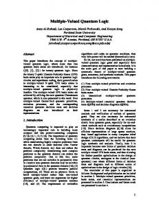
Figure 1. Illustration of the scheme. a, Two qudits encoded in d time bins and frequency bins in a single photon, going through a deterministic quantum process. The single-photon can be encoded in an arbitrary superposition of different time and frequency bins; the unused time-frequency slots are shown with dashed circles. After the deterministic quantum process operates on the two-qudit state, the orientation of the time-frequency superpositions change to a new two-qudit state. b, 2log2d photons holding one qubit each (shown in blue and red colors) go through a probabilistic quantum process, which make the same Hilbert space size as the single photon in a. The input/output qubits can be in the states red, blue or a superposition of the two. In b, there is a possibility that the photons do not come out through the desired outputs, hence the first two output qubits are not shown (signifying gate failure). ___________________________________________ compatible with fiber optical transmission—to encode one qudit in each DoF. We consider multiple time bins and frequency bins; as long as the frequency spacing between different modes (𝛥𝑓) and the time-bin spacing (𝛥𝑡) are chosen such that they far exceed the Heisenberg limit (i.e., Δ𝑓Δ𝑡 ≫ 1), we are able to manipulate the time and frequency DoFs independently in a hyper-encoding fashion, using concepts developed in time-division and wavelengthdivision multiplexing, respectively18,19. In other words, each time-frequency mode pair constitutes a well-defined entity, or plaquette18,19, which is sufficiently separated from its neighbors to provide stable encoding (Fig. 1a). An analogous process is at work in the advanced optical modulation formats gaining adoption in modern digital communications, where many bits are encoded in a single symbol via modulation of canonically conjugate quadratures20. Since our single photons can potentially be generated in a superposition of many time and frequency bins, multiple qubits can be encoded in each DoF, making our proposed scheme a favorable platform for
deterministic optical quantum computing algorithms on large Hilbert spaces. To show the capability of performing all singlequdit operations, it is sufficient to demonstrate the generalized Pauli gates X (cyclic shift) and Z (statedependent phase), which are universal for single-qudit operations14, and from which all 𝑑-dimensional Weyl operators can be constructed21. The Z gate applies a unique phase shift to each of the 𝑑 basis states, which can be easily executed with a phase modulator and a pulse shaper in the time domain and frequency domain, respectively. Specifically, for the basis state 𝑛 (𝑛 = 0,1, … , 𝑑 − 1), we have 𝑍 𝑛 = exp(2𝜋𝑖𝑛/ 𝑑) |𝑛⟩. Here, we demonstrate the much more challenging X gate, which realizes the transformation 𝑋 𝑛 = |𝑛 ⊕ 1⟩, where ⊕ denotes addition modulo 𝑑. Our version, presented in Fig. 2a, operates on time bins in three dimensions, a process which corresponds to state-dependent delay. Because the gate operates on each photon individually, we can fully characterize its performance with coherent states; the statistics of the input field have no impact on the principle of operation. Accordingly, we use a continuous-wave (CW) laser and prepare the desired weak coherent state by carving out three time bins 0 < , 1 < , 2 < using an intensity modulator and manipulating their relative phases with a phase modulator. The time bins are 3 ns wide and 6 ns apart from each other. To perform the X operation, we need to separate the time bins 0 < and 1 < from 2 < and delay the route for time bins 0 < and 1 < by 3 bins (18 ns). We realize the necessary spatial separation between the time bins with an integrated Mach-Zehnder modulator (MZM) switch. We emphasize that while most MZM designs are one-port devices, with one of the two output paths terminated, this 1x2 version permits access to both interferometer outputs, and accordingly it is in principle lossless—as required for a unitary operation. (In practice, of course, insertion loss reduces throughput, but this is of a technical nature and not fundamental to the method.) After the path-dependent delay, another 1x2 MZM, but operated in reverse, can be used to recombine the time bins deterministically as well. However, due to lack of equipment availability, in this proof-of-principle experiment we employ a 2x2 fiber coupler for recombination, which introduces an additional 3 dB power penalty. For our measurement scheme, we synchronize a single photon detector and time interval analyzer with the generated time bins. The transformation matrix performed by the X gate when probed by single time bins yields a computational basis fidelity ℱ> of 0.996 ± 0.001, shown in Fig. 2b (see Supplementary Information). As
a.
State Preparation
a.
X Gate MZM X Gate
IM State Preparation PM IM
PM
Event SPDTimer
MZM
SPD
PZT
Laser
Event Timer
State Measurement State Measurement
PZT
PZT
Laser
PZT
PZT
PZT
Arbitrary Waveform Generator Arbitrary Waveform Generator
b.
c.
b.
1
c.
Probability
0.8
0.5
0.6
0
0.4
i Ou j0 tpu 1i tS j tat e
0.2 j2
i
j0
i
j1
i
j2
i
Inp
tate ut S
0
Counts in 2 seconds
3000 1
2500 2000 1500 1000 500 0 -4:/3
0
-2:/3
2:/3
? [rad]
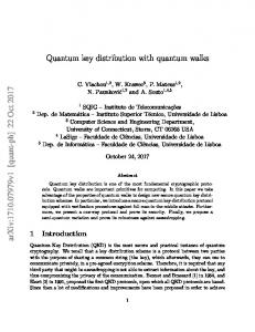
Figure 2. a, Experimental setup of the state preparation, the X gate, and the state measurement. IM: intensity modulator. PM: phase modulator. MZM: Mach-Zehnder modulator PZT: piezo-electric phase shifter. SPD: single-photon detector. The circle-shaped fibers indicate the delay; each circle is equivalent to one time-bin delay (6 ns). b, The transformation matrix. c, Counts measured after overlapping all three output time bins, for a time-bin superposition state input into the X gate. The blue errorbars are obtained from 5 measurements for each phase. The subtracted background was about 200 per 2 seconds. ____________________________________________________________________________________ such computational-basis-only measurements do not couple into a microring with a free spectral range reflect the phase coherence of the operation, we next (FSR) of 380 GHz, generating a biphoton frequency prepare superposition states as input and interfere the comb with mode spacing equal to this FSR. The timetransformed time bins after the gate with a cascade of bin and frequency-bin entanglement of such sources 1-bin and 2-bin delay unbalanced interferometers. In have been proven recently22–25. As our time-bin and order to combat environmentally induced phase frequency-bin spacings vastly exceed the Heisenberg fluctuations, we stabilize both these interferometers limit (𝛥𝑓𝛥𝑡 = 2280 ≫ 1), our time-frequency and the X gate by sending a CW laser in the backwards entangled photons can be considered hyperdirection and using a feedback phase control loop. We entangled—that is, entangled in two fully separable apply a phase of 0, 𝜙 and 2𝜙 to the time-bins 0 < , 1 < DoFs. The signal and idler photons from the first three comb line pairs are then selected and separated with a and 2 < , respectively, with the phase modulator in the commercial pulse shaper, as shown in Fig. 4a. Now state preparation stage and sweep 𝜙 from 0 to 2𝜋, that the time bins and frequency bins are all generated obtaining the interference pattern shown in Fig. 2c. in the state preparation stage, the idler photons are sent After subtraction of the background, we calculate a to a single photon detector to be used as heralding visibility of 0.94 ± 0.01 from the maximum and photons, and the signal photons are what carry the twominimum points, showing strong phase coherence (the qudits in the three time bins 0 < , 1 < , 2 < and ability to preserve and utilize coherent superpositions) between the time bins after the gate. If for concreteness frequency bins 0 F , 1 F , 2 F . This procedure lets we assume a channel model consisting of pure us prepare any time-bin/frequency-bin product state depolarizing (white) noise21, we can use this visibility 𝑚 < 𝑛 F (𝑚, 𝑛 = 0,1,2) of the full computational to estimate the process fidelity ℱD , finding ℱD = basis set. In principle, we could also herald arbitrary 0.92 ± 0.01 for the X gate (see Supplementary time-frequency superposition states in this setup, by Information). first sending the idler photon through a combination of With this high-performance time-bin X gate in timeor frequency-bin interferometers (e.g., the hand, we are then in a position to incorporate it into a beamsplitter in ref. 16) prior to detection in the frequency network to realize deterministic two-qudit temporal and spectral eigenbases. This more general gates, where the frequency DoF acts as the control and case would permit the preparation of any two-qudit the time DoF is the target qudit. For this state and is an important area for further research. demonstration, instead of a weak coherent state, we As the first two-qudit gate, we demonstrate the utilize true single photons, heralded by detecting the controlled-increment (CINC) operation (Fig. 3a), partner photon of a frequency-bin entangled pair where an X gate is applied to the time-bin qudit only generated through spontaneous four-wave mixing in when the frequency qudit is in the state 2 F . This twoan on-chip silicon nitride microresonator. The time bins, defined by intensity modulation of the pump,
b.
CINC Gate
00
01
01
02
02
10 11 12
10 11 12
20
20
21
21
22
filter and route it to a time-bin X gate (Fig. 4a); no operation happens on the route of the other two frequency bins. The frequency bins are then brought back together with another DWDM with zero relative delay to complete the two-qudit gate operation. To measure the transformation matrix of this gate in the computational basis, we prepare the input state in each of the 9 combinations of single time bins and frequency bins, using the first intensity modulator and the pulse shaper, respectively. We then record the signal counts in all possible output timebin/frequency-bin pairs, conditioned on detection of a particular idler time-frequency mode, by inserting three different DWDMs in the path of the signal photons to pick different frequency bins. The measured transformation matrix is shown in Fig. 4b, with accidental-subtracted fidelity ℱ> = 0.90 ± 0.01 (see Supplementary Information).
SUM Gate
00
Output State
Output State
a.
22 00 01 02 10 11 12 20 21 22
00 01 02 10 11 12 20 21 22
Input State
Input State
Figure 3. Ideal transformation matrices for the twoqutrit CINC (a) and SUM (b) quantum gates. The first qutrit is the frequency-bin qutrit and the second qutrit is the time-bin qutrit. The blue squares show the ones and the white squares show the zeros in the transformation matrices. __________________________________________ qudit gate along with single qudit gates X and Z form a universal set of gates required for any quantum computing algorithm6. To implement this gate, we separate 2 F from the other two frequency bins with a dense wavelength-division multiplexing (DWDM)
For the next step, we implement an even more complex operation, the SUM gate—a generalized controlled-NOT gate26—which adds the value of the control qudit to the value of the target qudit, modulo
a.
SUM Gate MZM
a.
MZM
PZT
Dispersion
PZT SUM Gate CINC Gate
Dispersion
IM
Idler Microring Microring
Pulse Shaper Pulse Shaper
Event Timer
SPDs
MZM MZM
IM
Laser Laser
SPDs
Event Timer
Signal
DWDM
PZT PZT
DWDM
DWDM DWDM DWDM DWDM
CINC Gate Arbitrary Waveform Generator Arbitrary Waveform Generator
b. b.
0.9
c. c.
0.8
1
0.9 0.8
1
0.6
0.5
0.5 0.4
0
i j 00 01i i j 02 i j 10 i Ou j 11 i tpu j 12 i j 20 i tS j 21 i tat j 22 e j
0.3
j 2 j 22i j 12 j 20i 1i j 1 i j 0 j 10i 1i e j 00 j 01i 2i Stat i put
In
0.2 0.1 0
0.7
Probability
Probability
0.7
0.6
0.5
0.5 0.4
0
i j 00 01i i j 02 i j 10 i Ou j 11 i tpu j 12 i j 20 i tS j 21 i tat j 22 e j
0.3
j 2 j 22i j 12 j 20i 1i j 1 i j 0 j 10i 1i e j 00 j 01i 2i Stat i put
0.2 0.1 0
In
Figure 4. a, Experimental setup for the CINC and SUM gate. The MZM for the CINC gate is driven such that it separates the time bin |2⟩ < from time bins |0⟩ < and |1⟩ < . For the SUM gate, the MZM separates the time bins that fall outside of the computational space (|3⟩ < and |4⟩ < ) from the computational space time bins (|0⟩ < , |1⟩ < and |2⟩ < ). DWDM: dense wavelength-division multiplexer. b and c, The experimental transformation matrix of the CINC and SUM gate, respectively. The accidentals were subtracted in the transformation matrices, and the coincidence to accidentals ratio was ~3.7 in the CINC and ~3 in the SUM case.
3. In this gate, the time bins associated with 0 F are not delayed, the time bins associated with 1 F experience a cyclic shift by 1 slot, and the time bins corresponding to 2 F go through a cyclic shift of 2 slots. To delay the time bins dependent of their frequencies, we induce a dispersion of -2 ns/nm on the photons using a chirped fiber Bragg grating (CFBG); this imparts 6-ns (1-bin) and 12-ns (2-bin) delays for the temporal modes of 1 F and 2 F , respectively, as required for the SUM operation. However, this delay is linear—not cyclic—so that some of the time bins are pushed outside of the computational space, to modes 3 < and 4 < . Returning these bins to overlap with the necessary 0 < and 1 < slots can be achieved using principles identical to the time-bin X gate with a relative delay of three bins. The experimental setup is shown in Fig. 4a, where we use the same techniques as for the CINC gate to measure the transfer matrix shown in Fig. 4c, with ℱ> = 0.92 ± 0.01. The fact that this SUM gate is implemented with qudits in a single step potentially reduces the complexity and depth of quantum circuits in all the algorithms that require an addition operation27. We note that to enhance computational capabilities, it would be valuable to also develop two-qudit operations where instead time bins are the control qudit and frequency bins the target qudit which would then require active frequency shifting conditioned on time bins. Hyper-entangled time-frequency entangled states, as opposed to other high-dimensional optical degrees of freedom like orbital angular momentum, can be generated in integrated on-chip sources, which have gained tremendous attention in recent years due to their low cost, room temperature operation, compatibility with CMOS foundries and the ability to be integrated with other optical components. These two degrees of freedom can be extended to much higher dimensions as well; in the frequency domain, a 50 GHz spaced biphoton frequency comb has been demonstrated with more than 40 frequency mode pairs25. For such a frequency spacing, independent time bins can be placed as close as ~20 ps to each other based on Heisenberg’s limit, implying ~50 modes available for encoding within a single nanosecond, limited only by detector timing resolution. Manipulating the frequency bins in both phase and delay should become possible with an on-chip pulse shaper28, removing the need for large dispersion modules like a CFBG. In addition, demonstration of balanced and unbalanced interferometers on-chip eliminates the need for active stabilization, which is of considerable profit for the scalability of the scheme29. These contributions can potentially lead to combining these sources with on-chip phase modulators, switches
and pulse shapers to create the whole quantum computing process on an integrated circuit. High-dimensional optical states24,25,29–31 can open the door to deterministically carry out various quantum computing algorithms in large Hilbert spaces32. We have demonstrated deterministic single and two-qudit gates using the time and frequency degrees of freedom of a single photon to encode the qudits, and carried out theses gates with a high computational space fidelity. Such demonstrations of deterministic quantum gates33 add significant value to the photonic platform for near-term quantum computing. Acknowledgments. We thank B. P. Williams for discussions on Bayesian estimation. Funding. J.M.L. acknowledges support from a Wigner Fellowship at ORNL. A portion of this work was performed at Oak Ridge National Laboratory, operated by UT-Battelle for the U.S. Department of Energy under Contract No. DEAC05-00OR22725. References. [1] Nielsen, M. & Chuang, I. L. Quantum Computation and Quantum Information. (Cambridge University Press, 2010). [2] O’Brien, J. L. Optical Quantum Computing. Science 318, 1567–1570 (2007). [3] Fiorentino, M. & Wong, F. N. C. Deterministic controlled-NOT gate for single-photon two-qubit quantum logic. Phys. Rev. Lett. 93, 070502 (2004). [4] Kagalwala, K. H., Di Giuseppe, G., Abouraddy, A. F. & Saleh, B. E. A. Single-photon three-qubit quantum logic using spatial light modulators. Nat. Commun. 8, 739 (2017). [5] Cerf, N. J., Adami, C. & Kwiat, P. G. Optical simulation of quantum logic. Phys. Rev. A 57, R1477–R1480 (1998). [6] Brennen, G. K., Bullock, S. S. & O’Leary, D. P. Efficient Circuits for Exact-universal Computationwith Qudits. Quantum Info. Comput. 6, 436–454 (2006). [7] Deutsch, D. & Jozsa, R. Rapid Solution of Problems by Quantum Computation. Proc. R. Soc. London A Math. Phys. Eng. Sci. 439, 553– 558 (1992). [8] Shor, P. W. Polynomial-time algorithms for prime factorization and discrete logarithms on a quantum computer. SIAM Rev. 41, 303–332 (1999). [9] Grover, L. K. Quantum mechanics helps in searching for a needle in a haystack. Phys. Rev. Lett. 79, 325–328 (1997).
[10] Somaroo, S., Tseng, C. H., Havel, T. F., Laflamme, R. & Cory, D. G. Quantum simulations on a quantum computer. Phys. Rev. Lett. 82, 5381–5384 (1999). [11] Devoret, M. H. & Schoelkopf, R. J. Superconducting circuits for quantum information: An outlook. Science 339, 1169–1174 (2013). [12] Cirac, J. I. & Zoller, P. Quantum computations with cold trapped ions. Phys. Rev. Lett. 74, 4091– 4094 (1995). [13] Crespi, A. et al. Integrated photonic quantum gates for polarization qubits. Nat. Commun. 2, 566 (2011). [14] Babazadeh, A. et al. High-Dimensional SinglePhoton Quantum Gates: Concepts and Experiments. Phys. Rev. Lett. 119, 180510 (2017). [15] Humphreys, P. C. et al. Linear optical quantum computing in a single spatial mode. Phys. Rev. Lett. 111, 150501 (2013). [16] Lu, H. H. et al. Electro-Optic Frequency Beam Splitters and Tritters for High-Fidelity Photonic Quantum Information Processing. Phys. Rev. Lett. 120, 030502 (2018). [17] Knill, E., Laflamme, R. & Milburn, G. J. A scheme for efficient quantum computation with linear optics. Nature 409, 46–52 (2001). [18] Fang, W.-T. et al. Towards high-capacity quantum communications by combining wavelength-and time-division multiplexing technologies. arXiv Prepr. arXiv1803.02003 (2018). [19] Humphreys, P. C. et al. Continuous-variable quantum computing in optical time-frequency modes using quantum memories. Phys. Rev. Lett. 113, 130502 (2014). [20] Marin-Palomo, P. et al. Microresonator-based solitons for massively parallel coherent optical communications. Nature 546, 274–279 (2017). [21] Wilde, M. M. Quantum information theory. (Cambridge University Press, 2013). [22] Jaramillo-Villegas, J. A. et al. Persistent energytime entanglement covering multiple resonances of an on-chip biphoton frequency comb. Optica 4, 655–658 (2016). [23] Reimer, C. et al. Generation of multiphoton entangled states with integrated optical frequency comb sources. Science 351, 1176-1180 (2016). [24] Kues, M. et al. On-chip generation of highdimensional entangled quantum states and their coherent control. Nature 546, 622–626 (2017). [25] Imany, P. et al. 50-GHz-spaced comb of highdimensional frequency-bin entangled photons from an on-chip silicon nitride microresonator. Opt. Express 26, 1825–1840 (2018).
[26] Wang, X., Sanders, B. C. & Berry, D. W. Entangling power and operator entanglement in qudit systems. Phys. Rev. A - At. Mol. Opt. Phys. 67, 8 (2003). [27] Draper, T. G., Kutin, S. A., Rains, E. M. & Svore, K. M. A logarithmic-depth quantum carrylookahead adde. Quantum Info. Comput. 6, 351– 369 (2006). [28] Wang, J. et al. Reconfigurable radio-frequency arbitrary waveforms synthesized in a silicon photonic chip. Nat. Commun. 6, 5957 (2015). [29] Wang, J. et al. Multidimensional quantum entanglement with large-scale integrated optics. Science eaar7053 (2018). [30] Ikuta, T. & Takesue, H. Four-dimensional entanglement distribution over 100 km. Sci. Rep. 8, 817 (2018). [31] Malik, M. et al. Multi-photon entanglement in high dimensions. Nat. Photonics 10, 248–252 (2016). [32] Erhard, M., Fickler, R., Krenn, M. & Zeilinger, A. Twisted photons: new quantum perspectives in high dimensions. Light Sci. &Amp; Appl. 7, 17146 (2018). [33] Hacker, B., Welte, S., Rempe, G. & Ritter, S. A photon-photon quantum gate based on a single atom in an optical resonator. Nature 536, 193–196 (2016).
Supplementary Material. For the time-bin single qudit X gate shown in Fig. 2, we split the experimental setup in three stages: state preparation, X gate operation and state measurement. For the state preparation, we use an Agilent 81645A CW laser tuned to 1553.9 nm and send it into an intensity modulator (~4𝑑𝐵 insertion loss) and phase modulator (~3𝑑𝐵 insertion loss), both manufactured by EOSpace, which are used to create the time bins and control their relative phases, respectively. To implement the X gate operation, we used an MZM with two complementary outputs (~4𝑑𝐵 insertion loss), also manufactured by EOSpace. We also use a piezo-based fiber phase shifter (General Photonics FPS-001) to control the phase difference between the two paths following the MZM. Then a 2×2 3dB fiber coupler is used to merge the branches. For the state measurement, we used 1-bin and 2-bin delay interferometers implemented with 2×2 3dB fiber couplers and additional piezo-based fiber phase shifters. A gated InGaAs single photon detector (Aurea Technologies SPD_AT_M2) and a time interval analyzer (PicoQuant HydraHarp 400) are used to measure the interval from a trigger signal and the photon arrival time. The stabilization of the interferometers is done by sending a CW laser at 1550.9 nm in the backwards direction and feeding the output power into a computer-based feedback loop to maintain the phase. To stabilize the X gate, we use a similar scheme with an additional circulator at the input of the gate (not shown in the figures) to retrieve the optical power in the backwards direction. The signal applied to the intensity modulators and phase modulator, as well as the trigger and synchronization signal of the single photon detector and time interval analyzer, are generated by an electronic arbitrary waveform generator Tektronix AWG7122B and adjusted to the proper level by linear amplifiers. To assess the performance of our one- and twoqudit quantum gates, we first focus on the computational-basis fidelity ℱ> —one example of a socalled “classical” fidelity in the literature1. Defining 𝑛 (𝑛 = 0, 1, … , 𝑁 − 1) as the set of all computational basis states and |𝑢Q ⟩ as the corresponding output states for a perfect operation, we have the fidelity 1 ℱ> = 𝑁
STU
𝑝(𝑢Q |𝑛) QVW
(1)
where 𝑝(𝑢Q |𝑛) is the probability of measuring the output state |𝑢Q ⟩ given an input of |𝑛⟩. In the operations considered here, the ideal output states |𝑢Q ⟩ are members of the computational basis as well, so there is no need to measure temporal or spectral superpositions in determination of ℱ> . Given the
measured counts, we retrieve the 𝑁 conditional probability distributions via Bayesian mean estimation (BME)2,3,where our model assumes that each set of count outcomes (after accidentals subtraction) follows a multinomial distribution with to-be-determined probabilities; for simplicity, we take the prior distributions as uniform (equal weights for all outcomes). We then compute the mean and standard deviation of each value 𝑝(𝑢Q |𝑛) and sum them to arrive at ℱ> . Specifically, if 𝐶YZ|Q signifies the counts measured for outcome 𝑢Q , and 𝐶[\[|Q the total counts over all outcomes (both for a given input state |𝑛⟩), BME predicts: 𝑝 𝑢Q 𝑛 = ±
1 + 𝐶YZ|Q 𝑁 + 𝐶[\[|Q
1 + 𝐶YZ|Q 𝑁 + 𝐶[\[|Q
𝑁 + 𝐶[\[|Q − 𝐶YZ|Q − 1 ^ 𝑁 + 𝐶[\[|Q + 1
(2)
where the standard deviation in the estimate is used for the error. Since the probabilities here each actually come from 𝑁 different distributions, we estimate the total error in ℱ> by adding these constituent errors in quadrature. Explicitly, we find ℱ> = 0.996 ± 0.001 for the X gate, 0.90 ± 0.01 for the CINC operation, and 0.92 ± 0.01 for the SUM gate. The reduction in ℱ> for the two-qudit gates is due in large part to the fewer total counts in these cases, from our use of heralded single photons rather than a weak coherent state. As seen by the presence of N in the denominator of Eq. (2), even when 𝐶YZ|Q = 𝐶[\[|Q , the estimate 𝑝 𝑢Q 𝑛 is not unity unless 𝐶[\[|Q ≫ 𝑁. In our experiments, the two-qudit tests have only ~100-300 total counts (with N=9), thereby effectively bounding the maximum 𝑝 𝑢Q 𝑛 and, by extension, fidelity ℱ> . This behavior is actually a strength of BME, though, as it ensures that we have a conservative estimate of the fidelity that is justified by the total amount of data acquired2. While extremely useful for initial characterization, however, the computational-basis fidelity above provides no information on phase coherence. On the other hand, process tomography would offer a complete quantification of the quantum gate. Yet due to the challenging experimental complexity involved in quantum process tomography, here we choose a much simpler test which—while limited—nonetheless offers strong evidence for the coherence of our timebin X gate. To begin with, note that all threedimensional quantum process can be expressed in terms of the nine Weyl operations4:
1 𝑈W = 𝐼 = 0 0
0 1 0
0 0 0 , 𝑈U = 𝑋 = 1 1 0
1 𝑈a = 𝑍 = 0
0 𝑒
0 1 𝑈g = 𝑍 ^ = 0
c
^d a
0
0
0
c
^d
,
𝑈e = 𝑍𝑋 = 𝑒
𝑒 Tc a
0 0
0
𝑒 Tc j
0
hi
0 0 1
hi
1 0 0 , 𝑈^ = 𝑋 ^ = 0 0 1
^d a
0
1 0 ,
0
^d
0 0
hi
, 𝑈k = 𝑍 ^ 𝑋 = 𝑒 Tc j
1 0 0 0
^
𝑈f = 𝑍𝑋 =
0 1 0 1
0
0
0
c
^d
𝑒 Tc a
0
𝑒 Tc a
0
0
1
0
1
0
0 , 𝑈l = 𝑍 ^ 𝑋 ^ =
0
0
hi
hi
𝑒
^d a
0 0
hi
𝑒 Tc j (3)
0 0 𝑒c j 0 𝑒c j 0 𝑒c j 0 0 _____________________________________________________________________________________________ The quantum process itself is a completely positive map ℰ 5, which for a given input density matrix 𝜌op outputs the state l
𝜒sQ 𝑈s 𝜌op 𝑈Qt (4)
𝜌\q[ = ℰ 𝜌op =
ℱD = 𝑇𝑟 𝜒u 𝜒S = 𝜒S
UU
= 0.92 ± 0.01
=
1 + 8𝜆 1 + 5𝑉 = 9 9 − 3𝑉 (7)
as discussed in the main text.
s,QVW
The process matrix with elements 𝜒sQ uniquely describes the operation. The ideal three-bin X gate with process matrix 𝜒u has only one nonzero value, [𝜒u ]UU = 1. To compare to this ideal, we assume the actual operation consists of a perfect X gate plus depolarizing (white) noise6. In this case we have a total operation modeled as (1 − 𝜆) 𝕀a (5) 3 whose process matrix we take to be 𝜒S = 𝜆𝜒u + UT{ 𝕀| . If we then assume a pure input superposition | state 𝜌op = |𝜓op ⟩⟨𝜓op |, where 𝜓op ∝ 0 < + 𝑒 c€ 1 < + 𝑒 ^c€ 2 < , and measure the projection onto the output 𝜓\q[ ∝ 0 < + 1 < + 2 < (as in Fig. 2c), 𝜆 can be estimated from the interference visibility 𝑉 as7: 2𝑉 𝜆= (6) 3−𝑉 and the process fidelity is then given by: 𝜌\q[ = 𝜆𝑈U 𝜌op 𝑈Ut +
References. [1] De Greve, K. et al. Complete tomography of a high-fidelity solid-state entangled spin-photon qubit pair. Nat. Commun. 4, 2228 (2013). [2] Blume-Kohout, R. Optimal, reliable estimation of quantum states. New J. Phys. 12, 043034 (2010). [3] Williams, B. P. & Lougovski, P. Quantum state estimation when qubits are lost: A no-data-leftbehind approach. New J. Phys. 19, 043003 (2017). [4] Bertlmann, R. A. & Krammer, P. Bloch vectors for qudits. J. Phys. A Math. Theor. 41, 235303 (2008). [5] O’Brien, J. L. et al. Quantum Process Tomography of a Controlled-NOT Gate. Phys. Rev. Lett. 93, 80502 (2004). [6] Wilde, M. M. Quantum information theory. (Cambridge University Press, 2013). [7] Thew, R. T., Acin, A., Zbinden, H. & Gisin, N. Bell-type test of energy-time entangled qutrits. Phys. Rev. Lett. 93, 10503 (2004).