010-019•develop&perform
9/4/06
10:01 AM
Page 10
DEVELOPMENT AND PERFORMANCE TESTS OF A SEPARATOR FOR REMOVAL OF PHYSICALLY EMULSIFIED AND FREE OILS FROM WASTEWATERS Law Puong Ling, Ngu Lock Hei, Wong Kien Kuok and Awangku Abdul Rahman Pgn. Hj. Yusof Department of Civil Engineering, Universiti Malaysia Sarawak, 94300 Kota Samarahan, Sarawak E-mail:
[email protected]
ABSTRACT A novel oil-water separator with multiple angles parallel coalescence frustums for removal of physically emulsified and free oils from wastewater was recently developed. Performance tests had been carried out to determine its removal efficiency. The primary component of the separator includes a series of inverted and upright frustums-shaped coalescence plates to form a multiple angle plate arrangement for enhance gravity separation and coalescence of oil droplets. The oil removal efficiency (E) of this separator was found to be inversely proportional to influent flowrate (Q) and directly proportional to retention time, t. The efficiency (E) of this separator can be expressed as a function of flowrate (Q), retention time (t), and influent oil concentration (Coil) by a series of power equations; E = 59.689Q-0.107 for Coil = 100 mg/L, E = 70.753Q-0.1269 for Coil = 1000 mg/L, and E = 40.16t0.127 for Coil = 1000 mg/L. For Coil = 100 mg/L, E could be best expressed by polynomial equation, i.e., E = 0.0001t2 + 0.0045t + 57.147. The highest achievable oil-water separation efficiency of this separation system was approximately 82.4% at a flowrate (Q) of ≤ 5x10⁻⁶ m3/s, and retention time of ≥ 4.80 hours. It was found that the presence of an outlet baffle component for the separator could improve oil removal efficiency by approximately 12.9% as compared to without an outlet baffle. Keywords: Coalescence Frustums, Emulsified and Free Oils, Oil-water Separation, Removal Efficiencies
1. INTRODUCTION At present, the simplest systems are often inadequate and more complicated systems are either too expensive or too maintenance-intensive [1]. Some of the common separators in use with various designs include 1) American Petroleum Institute (API) Separators, 2) Coalescing plate separators, 3) Coalescing tube separators, and 4) Packing type separators. Burns and Mohr [2] used a coalescing plate separator to treat coolant contaminated with tramp oil. Foley et al. [3] upgraded a refinery "once-through" cooling water systems from a gravity separator with 8 pits arranged in 2 trains with the additional of multiple-angle coalescing plate module. Saleh and Hamoda [4] upgraded of a conventional rectangular sedimentation tanks by applying inclined plate settlers in secondary sedimentation to improve its performance. Veenstra et al. [5] provided an overview of oil-water separation as used in the petroleum refining industries. The two API separators were converted into four cells by adding multiple angle coalescing media pack, divider walls and additional inlet/outlet piping. Schlegel and Stein [6] proposed to feed the sludge/water mixture directly into the sludge layer on the bottom of the secondary sedimentation tanks. Demír [7] carried out a study to determine the settling efficiency and optimum plate angle for a rectangular settling tank with inclined parallel plate.
removal efficiency, E in relation to the specific design and influent parameters such as oil concentrations, flowrates and retention time.
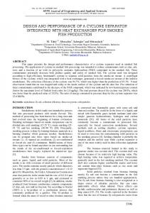
2. HYPOTHESIS In the 1920's, Boycott noticed that blood cells settled faster in test tubes that were inclined than in tubes that were straight up or vertical. Acrivos and co-workers developed a theoretical basis, but the general concept is not difficult to grasp [8]. As illustrated in Figure 1, when the settler is inclined, the falling particles and the rising liquid get out of each other's way. In vertical tube, particles settling displace fluid that must rise. An element of this fluid passes past more particles and has to accelerate and decelerate depending on whether its path is wide or narrow. The vector arrows for the enlarged view are the same at the start, but eventually the inclined tube gets the particles near the wall where their direction changes. In this region, they are denser than in the vertical tube, and the liquid has a shorter
1A. OBJECTIVES The objectives of this research project includes (a) to develop an enhanced oil-water separation system with multiple angles of parallel coalescence frustums for removal of physically emulsified and free oils from water suitable for small to medium volume of municipal wastewater loaded with oil and grease, and (b) evaluate and determine the separation system oil 10
Figure 1: Comparison of particle settling in a vertical tube and an inclined tube Journal - The Institution of Engineers, Malaysia (Vol. 67, No. 2, June 2006)
010-019•develop&perform
9/4/06
10:01 AM
Page 11
DEVELOPMENT AND PERFORMANCE TESTS OF A SEPARATOR FOR REMOVAL OF PHYSICALLY EMULSIFIED AND FREE OILS FROM WASTEWATERS
distance to escape from them. This phenomenon is good to enhance separation and therefore inclined medium is recommended. Generally, the mechanisms of oil droplets gravity separation include the principles of Stokes’ Law [9] and Boycott effect [8]. Separation of oil from water is a liquid-liquid separation carried out almost exclusively by gravity separation using flotation of the oil droplets to remove it from water, either natural or enhanced. Natural gravitational separation is carried out in American Petroleum Institute (API) separators and in large tanks [10]. Enhanced gravitational separation is accomplished with centrifugal units, air floatation and flocculation units, and in various type of coalescing plate separators [2]. Oil in water is characterized by a spectrum of droplet sizes. The droplet size that must be removed to attain a given effluent concentration depends on the oil specific gravity, concentration and average droplet size present. Design of an enhanced gravity separator size employs the mechanism of the rise velocity, vr of the oil droplets. Droplets rise velocity, vr is given by Stokes’ Law [9]:
(1)
where:
vr = rising velocity of the oil droplet size that is 100% removed, m/s g = acceleration due to gravity, m/s2 µ = dynamic viscosity of continuous liquid, Pa.s ρo = mass density of the oil droplet, kg/m3 ρ = mass density of continuous liquid, kg/m3 d = diameter of oil droplet, m
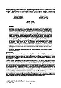
coalescing frustums promotes optimum oil-liquid separation by providing the inclined medium for Boycott’s effect to take place. As illustrated in Figure 1 fluid elements in the inclined tube escape quicker from the oil droplets and flow more easily. Furthermore, as the oil droplets suspension gets more concentrated it also gets denser. This provides more driving force for rising. The net effect is that the oil droplets coalesce and slide up along the plate while liquid flows downward with less interference than in the vertical medium. The tiny or small oil and grease droplets would coalesce and form bigger droplets as they slide along the bottom side of the frustum. Eventually the oil droplets would float to the surface. Thus, the separation of oil and grease from wastewater could be achieved. The proposed separation technique is very much dependent on the arrangement and orientation of the coalescence frustums, the frustum spacing and the total surface area of the frustums. However, other factors such as influent concentration, flowrates, viscosity and specific gravity, rising properties, volumes of the systems, temperature, and fluid pH are undoubtedly playing important roles in removal or separation efficiency of oil and grease from wastewater. The features of the proposed separator as shown in Figure 2 consist of: a. Circular separation tank to take advantage of the continual decrease in horizontal velocity, b. Perforated pipe center-feed (upflow) inlet with inlet well, c. Parallel coalescence frustum, and d. Outlet baffle, periphery overflow outlet weir channel to give uniform flow removal and outlet launder to direct effluent out of the separator.
The rise velocity of the oil droplets represents the overflow rate, vo of the separation tank and is expressed as flowrate per unit area [11]. The overflow rate, vo is then used to calculate the required plan area, Ap given in the equation below:
(2)
Sufficient volume should be provided to allow the oil droplets entering the separator to rise to the surface (to be captured) before the water carrying the droplets exits the opposite end of the separator. The retention time, t is equal to the volume of the separation tank, V divided by flowrate, Q given in the equation below. (3)
3. SEPARATOR DEVELOPMENT In this research, a centre-feed upflow circular tank separation technique was proposed to enable wastewaters loaded with physically emulsified and free oils to flow into the system and allow the horizontal velocity, vh to decelerate with distance from the inlet, as a result of continual increase of surface area. The reduction in horizontal velocity, vh would enhance the rising rate for most oil droplets. At the same time, the presence of Journal - The Institution of Engineers, Malaysia (Vol. 67, No. 2, June 2006)
Figure 2: Proposed circular separator with parallel inclined coalescence frustums (consisting of up-right and inverted series of conical frustums)
3A. APPLICABILITY OF COALESCENCE FRUSTUMS The installation of embedded successive layers of parallel coalescing frustums was expected to serve two purposes, i.e., 11
010-019•develop&perform
9/4/06
10:01 AM
Page 12
LAW PUONG LING, et al.
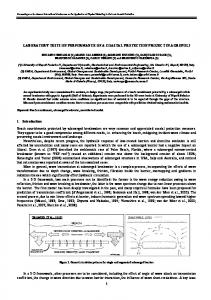
1) to promote laminar flow, and 2) to promote optimum oilwater separation efficiency. By using the principles of a) a maximum amount of frustum surface area provided for oil droplets coalescence to take place, and b) a minimum distance (spacing inversely proportionally to distance from inlet) for lighter oil droplets to rise and hit the bottom side of the frustums as shown in Figure 3. The coalescing frustums assist oil droplets to coagulate and float to the surface to be collected.
Figure 3: Parallel inclined coalescing frustums: Mechanism of oil-water separation
The use of coalescence frustum facilitates the capture of oil droplets from water, and easy removal of captured oil from the frustums to the surface. Captured oil spreads on the surface of the frustums and coalesces into larger droplets and eventually forms a film of oil on the frustums. It was necessary, having captured the oil on the frustums, to remove it from the frustums in an orderly manner that does not re-entrain the oil into the wastewater stream. The design of coalescence frustums was such that coalesced droplets were required to travel 10 cm (maximum) before they encountered an oil port. These oil ports are vertically aligned so that when the oil droplets are released from the frustums, they rise directly to the surface. Droplets are released from the frustums when they become large enough that the buoyancy due to their size overcomes the attractive forces holding the droplets onto the frustum. The tendency for the movement of the water horizontally through the frustum packs to "tear off" the droplets from the frustums also exists. The forces holding the droplets and/or film onto the frustums are due to molecular attraction, and are proportional to the area of contact between the oil and the frustum. The force trying to "tear off" the droplets is the frictional force due to the movement of the water. This frictional force is proportional to the surface area of the droplets and the flow velocity of the water. In conventional inclined plate medium, plates extend from one side of the separator to the opposite side, any and all captured oil must progress along the entire length of the plate before exiting to the surface at the opposite side of the separator. In a large separator, this could be eight (8) feet or more. This means that the amount of oil running along the underside of the plates increases as it moves upward along the sloped under surface of the plates. This gives the flowing water additional opportunities to remove the oil from the plates and carry it downstream, especially if enough oil is captured to partially fill the space between the plates, thus locally increasing the velocity of the water. Even if the oil does not 12
restrict the flow, larger droplets have more tendencies to be removed from the plates. Oil droplets released from the front portion of the packs would probably be captured by subsequent plates, but droplets released in this manner by the downstream end of the packs could exit the separator with the water. The proposed design provides oil port as illustrated in Figure 3 for the quick release of oil from the frustums in an orderly and systematic manner. Oils float to the surface of the separator instead of being forced to flow additional distances along the frustums before it was released. The sooner the oil floated to the surface the better is its chances of being permanently separated from water. The proposed separator was to be designed as a circular settling basin with parallel coalescence frustums. Settling basin consists of three zones, the inlet, outlet and separation zone. The separation tank was designed to separate all oil droplets sizes of more than 10 µm in diameter with following assumptions: • Oil droplets rise as discrete particle, free rising, • Oil droplet shape factor, φ = 1 (spherical), • Laminar flow, Reynold’s Number, (NRe) < 1 [12], • Separation basin is an ideal circular separation system with center-feed flow, and • Steady-state with even distribution of flow entering and leaving the tank
3B. PERFORATED-PIPE DISTRIBUTOR INLET Design of separation tank inlet velocity would be maintained