Development and validation of a Simulator for Wireless Data Acquisition in Gas Turbine Engine Testing (WIDAGATE) 1
1
6
2
7
2
Xuewu Dai , John E. Mitchell , Yang Yang , Ian Glover , Konstantinos Sasloglou , Robert Atkinson , Isabella 3 3 4 5 Panella , John Strong , Werner Schiffers , Partha Dutta 1 Department of Electronic & Electrical Engineering, University College London, London, UK, WC1E 7JE 2 Department of Electronic and Electrical Engineering, University of Strathclyde, Glasgow, UK, G1 1XW 3 SELEX Galileo Ltd, Basildon, UK, SS14 3EL, 4 Strategic Research Centre, Rolls-Royce plc, PO Box 31, Derby, UK, DE24 8BJ 5 Advanced Technology Centre, Rolls-Royce Singapore, 16 International Business Park, Singapore 609929 6 Shanghai Research Center for Wireless Communications (WiCO), Shanghai, China 7 AGT Group (R&D) GmbH, Hilpertstrasse 20a, 64295, Darmstadt, Germany Email:
[email protected] ABSTRACT Due to its cable-free deployment, wireless sensor networks (WSNs) have drawn great attention as a new technique for industrial data acquisition. However, the harsh environment of the gas turbine engine provides a number of challenges to the deployment of wireless sensors. A definitive study of the impacts of harsh environments on the WSNs is currently lacking, which represents an obstacle to WSN’s deployment in safety-critical industrial instrumentation and automation. In this paper, we report the test results of applying WSNs to data acquisition in gas turbine engine testing and the development of a realistic software simulator with the purpose of de-risking the wireless data transmission technology in a project called WIDAGATE. This paper provides an overview of the simulation platform developed and investigates how small-scale tests of a WSN deployed on a real engine were used to validate and improve the simulator platform. This work proposes the realistic modelling of the physical layer (radio channel) when subject to interference in harsh industry environment during aero engine testing. Based on the validated, realistic physical layer model, different MAC protocols are simulated to demonstrate how this improved simulator can be used to select an appropriate protocol.
1. INTRODUCTION With the rapid development of wireless techniques, wireless data transmission using sensors to monitor aero engine systems is increasingly being viewed as a means of reducing time to market in engine testing. Current wired communication systems for engine data acquisition involve extensive wiring harnesses, which leads to long, complicated and expensive setup procedures. Using wireless links instead of fixed copper wires has obvious advantages. Wireless sensor networks (WSNs) offer the data collection system flexibility with the potential to save setup costs, reduce deployment time and avoid failure in communication cables (such as connector faults and wrong connections) by reducing the complexity of the wiring required, which is particularly important for engine testing and instrumentation applications.
1
In order to ensure reliability it is of critical importance to understand the suitability of the proposed WSN techniques by estimating their performance in such harsh electromagnetic environments. However, the inherent stochastic nature of wireless communication (i.e. interference, channel fading and medium access control) present challenges for analytical studies wishing to capture the complexity of the whole communication network. Experimentation on large-scale hardware test-beds could be very time consuming and costly, while a small-scale test-bed may not reveal scalability problems. Although discrete-event simulators (like NS3, OMNeT++, OPNET) have been widely accepted as a tool for studying WSNs, the difficulty of software simulation is its fidelity and reality [1]. This is particularly true for WIDAGATE due to the lack of realistic radio channel models for harsh environments. One way of overcoming these problems is the combination of software simulation with small-scale hardware tests in realistic environments. Discrete event simulators are a standard tool to study communication network protocols. From the viewpoint of discrete event simulation, their capabilities of capturing and repeating the behaviours of a network are equivalent. If same algorithm and mathematical model representing the network layers are used in these simulators, the simulation results will be consistent. This is particularly true to the simulation of MAC/Network/TCP/Application layers, as many good models of the higher layers have been implemented in these simulators and their performances have been well demonstrated. Although discrete-event simulators have been widely accepted as a tool for studying wireless networks due to its scalability, flexibility and cost efficiency (compared to hardware tests), the main disadvantage of software simulation is its fidelity and reality. These simulators provide a powerful simulation platform, but they mainly use a packet level abstract model (e.g. a Gaussian random generator to determine if a packet is received successfully) representing the complicated physical layer processes. There has been a lack of direct support for highly accurate modelling of complex wireless environments and the bit stream processing in physical layer. In contrast to the wired channel, the wireless channel has a complex influence on the protocol performance and requires in-depth investigation to understand the performance of wireless techniques in an industrial process scenario. In WIDAGATE, a realistic radio channel model is essential to successfully estimate what performance the wireless network can achieve in the harsh environment experienced. One way of overcoming these problems of scalability of hardware tests and the reality of software simulation is the combination of software simulation with small-scale hardware tests in realistic environments. More specifically, the software simulator can be improved by developing a detailed and realistic physical layer and make use of the small-scale hardware test to validate the model’s fidelity. By doing so, a good trade-off between time, cost and accuracy can be achieved.
2
Another issue pertinent to the WIDAGATE project is the lack of 3D support. In WIDAGATE, most of the sensors are deployed in the limited space around or within the engine, which can be approximated by a steel cylinder. As the deployment of the sensor nodes is around an engine in 3 dimensions, a 3D location and radio and interference model is essential to achieve a comprehensive and accurate simulation. In order to achieve a high accuracy of the physical model in engine testing environment, a resolution of centimetre level is desired for both the radio channel model and 3D location of sensor nodes. In this paper we describe the design and validation of a 3D physical model for the development of a realistic wireless network simulator. Although the final objective of the WIDAGATE simulator is to determine the performance (throughput, latency and fairness) of various MAC protocols in an aerospace environment, the main objective of this paper is to study the integration and validation of a channel model into a discrete simulation environment. The detailed simulation of different MAC protocols and various techniques is beyond the scope of this paper and interested reader is referred to [2]. For illustration purposes, we present the simulation results of CSMA/CA and polling protocols to compare the performances of contention-based and collision-free protocols to demonstrate the use of the simulator for evaluating and selecting suitable MAC protocols in terms of overall network throughput. The rest of this paper is structured as follows: section 2 gives a brief description of related work and section 3 presents a system view describing the problem and requirements of WIDAGATE. The node structure of the developed simulator is presented in section
followed by sections 5 and 6 which describe the development of the physical model and MAC
modules respectively. Hardware tests and simulation validations are presented in section 7. The simulation results of the improved simulator and an application example of the developed simulator are given in section 8.
2. RELATED WORK OMNeT++ is a modular, discrete-event simulator implemented in C++ and is becoming a popular tool for developing various network simulators. Powered by the OMNeT++ simulation engine [3], many extension packages have been developed for WSN. Some examples are Mobility Framework (MF) [4], Castalia [5]. MF focuses on mobile wireless networks with an emphasis on localisation and MAC protocols while Castalia is for general purpose simulation of WSN. As a general wireless and mobile networks simulation framework,
MiXiM (MiXed siMulator) [6] [7] has been recently
developed by integrating several OMNeT++ simulator packages and features such as improved radio channel simulation. Since MiXiM provides a good framework supporting detailed simulation of physical layers allowing users to develop their own radio model, the physical model was built within the framework of MiXiM. Although developed for OMNeT++ the radio channel model could be easily implement in other event-driven platforms such as NS2 or OPNET.
3
“In the simulator validation, Colesanti etc. compared the OMNeT++ simulation of the flooding algorithm with a six-node (Tmote Sky) testbed [13]. Their results showed that simulation results tend to over-estimate the metrics collected in the testbed and suggested that a correcting factor derived from experiment has to be considered to improve the simulation reality. In [14], the simulation performances of some MAC protocols were compared with a Tnodes testbed. The authors suggested that a simple SNR-based reception model can provide quite accurate results for metrics commonly used to evaluate MAC protocols. In [15], the results of experiments on Motelab testbed were used as a baseline to evaluate the accuracy of NS-2 and Castalia simulators. In [16], a network consisting of four 802.11g nodes distributed among the range of 0.5m to 1.5m in an almost error free environment was used to validate the IEEE 802.11g model in OMNeT++. The metrics like throughput, delay and packet inter-transmission were adopted. Their results showed that the simulation results match the measurements well in most cases and the main differences were also pointed out. In the validation of wireless channels, a real WSN test in forest environment was reported in [17] and compared with three simulators, namely OMNeT++, Castalia and Shawn. Paper [17] focused on the accuracy of the path loss model in these simulators and concluded that the OMNeT++’s free space path loss model performs a bit better in terms of the simulation of receiving signal strength. It should be pointed out that, most of the existing works are on the basis of a general-purpose testbed in office environment, except [17] which was tested in the forest environment. Moreover, these testbeds and associated simulators were developed for 2-dimentional deployment under line-of-sight condition. However, our simulator and validation are for 3-D deployment uniquely for the gas turbine engine environment, in which non-line-of-sight has to be considered. Due to the open source nature of these OMNeT-based WSN simulators, they can be extended to cover almost all possible implementations and features. However, to the best of our knowledge they have not previously been modified to investigate the impact of electromagnetic interference in harsh industrial environments. In addition, most existing simulation platforms assume a 2D deployment of the sensor nodes and adopt an open-area line-of-sight channel fading model. However, in the engine testing scenario considered in this project, sensor nodes are deployed along the surface of the engine, modeled as a steel cylinder, which has significant impact on the wireless channel. With aero engines typically in the range of a few meters and potentially requiring many hundreds of sensors, the node density could be very high. The WIDAGATE simulation platform has been designed to investigate the suitability of wireless techniques for industrial data acquisition and de-risk the investment in the development of wireless data transmission technologies. The results of such a simulator and the quality of the performance evaluation depends heavily on the accuracy of the simulation environment,
4
e.g., environment interference, network topology and traffic patterns. If the simulator does not reproduce the characteristics of real-world environment, the developed product may fail after deployment in real networks in spite of promising results achieved in simulation. Based on the framework provided by OMNeT++ and MiXiM, we develop the WIDAGATE simulator incorporating realistic radio channel modeling, validation by hardware test-bed and the evaluation of various MAC protocols in a 3D engine environment.
3. SYSTEM OVERVIEW The simulation platform is intended to simulate an industrial wireless communication network for data acquisition during engine development and testing. The requirements of engine testing lead to the following main design considerations:
Simulation environment: The wireless communication network may have hundreds up to a few thousand of nodes resulting in a high node density which must be supported by the simulator. Therefore simulation models must be hierarchical and components should be modular and reusable.
Physical Models: The simulation platform will need to accurately represent the complex RF (Radio Frequency) and physical conditions encountered in an active aero-engine.
Traffic pattern: During the engine testing, the data traffic is generated by a sampling process at a constant but adjustable sampling frequency. In contrast to many simulators in which the package arrival is assumed to be Poisson distributed, the periodic sensor measurements in our data acquisition system tend to generate a periodic data flow. For the purpose of engine development and condition monitoring, large amounts of data are generated, which creates a high traffic load in the communication network. Some of the periodically generated sensor data requires real-time processing and fast delivery to the data collectors to ensure safety within the condition monitoring system.
Network Topology: In this application the network dynamics are limited as the sensor nodes are stationary, deployed in a grid-like topology along the surface of the engine and split into spatial sub-groups. Furthermore, considering the requirement of real-time transmission for high priority data, it is essential to improve spectral efficiency and reduce the communication hops. Therefore, an appropriate topology is the cluster tree network [8], as illustrated in Figure 1 where sensor nodes are hierarchically organised into clusters consisting of a cluster head (CH) and a set of child sensor nodes (SN). Within a cluster, the CH communicates with its associated child sensors in a one-hop fashion. These CHs are connected in the form of a tree. Once received from the child sensors, the CHs in turn forward the data to the data collector, either directly or via a multi-hop path through other intermediate CHs.
Protocols and high spectral efficiency: During engine development testing, up to 3000 sensors (thermocouples, pneumatic lines and accelerometers) are required to measure and record the temperature, pressure, and vibration.
5
The periodically generated data and high density of sensors result in a huge amount of data to be transmitted across the network. Thus, a high data rate and high spectral efficiency are essential to achieve low latency operation. Considering the relatively short duration of the engine test (usually a few hours), energy consumption is given lower priority in WIDAGATE. Therefore, the IEEE 802.11 protocols of higher data rate are preferred than the low-powerconsumption but low data rate IEEE 802.15.4 protocols, although the later may be used for low-sampling-rate sensors (i.e. thermocouples). The overall network throughout is of more interest than the allocation of bandwidth to different traffic categories. Hence, we do not consider different data type and services, as they are related to the high level above the PHY layer and have limited impact on the overall throughput. In the WIDAGATE cluster network, the communication system is divided into two parts; Single hop Sensor-toCluster-head (SN-to-CH) communication within a cluster; Multi-hop Clusterhead-to-Clusterhead (CH-to-CH) relay among cluster heads. In order to improve the spectral efficiency by reducing the channel interference, the CHs are equipped with two independent radio modules working at two non-overlapped channels respectively. One is for the SN-to-CH communication and another one for the CH-to-CH communication. Furthermore, the simulation platform must support various MAC protocols including CSMA/CA, TDMA, polling, etc. in order for studies to be conducted to optimize the network throughput and transmission latency. CSMA is a contention-based, distributed, random channel access control protocol typically used for distributed networks without time synchronization, while TDMA is a collision-free deterministic channel access control protocol that offers high channel utilization but requires good timing and central coordination.
4. NODE MODULES The simulator consists of a number of different kinds of nodes, including child sensor nodes, cluster heads and a data collector (implemented by the gateway node). A typical cluster in the network consists of twenty sensor nodes deployed around the surface of one engine module (e.g. the compressor) and two cluster heads (one is the working cluster head and one is a backup) are located at the bottom of the engine module. The active CH receives packet from sensor nodes and replies with ACK and commands (e.g. adjust the sampling rate). The backup CH works as a ‘sniffer’ node monitoring the traffic in the air. The backup CH keeps listening to the channels without sending any packets unless the active CH is found faulty. If the active node does not behave as expected (e.g. no ACK for a series of packets in a row), the backup CH will invoke communication with the active CH through the CH-to-CH channel and decide if the backup CH will replace the active CH [12]. The clusters are pre-determined based on the sensor structure (or measurement requirements) of the aero-engine under test. A wireless node (either sensor node or cluster head) in our simulator includes several modules: the application layer, the
6
network layer and a compound NIC (Network Interface Card) module containing the MAC layer and the physical layer. It is worth noting that an additional management sub-layer is inserted between the MAC layer and the network layer to simulate the wireless management, such as authorizing, association and channel assignment. The main task of the application layer is to generate the measurement data periodically according to the sampling rate. The network layer encapsulates the data from the application layer by adding an IP header. In our simulation platform, various NIC modules (e.g. Nic80211 for CSMA/CA in Ad Hoc mode, NicMacPollSN for sensor node in polling scheme, NicTDMACN for cluster head in TDMA scheduling, etc.) have been developed to support various MAC protocols. Each node also contains two support modules. The mobility module maintains a three-dimensional vector [x,y,z] to represent the 3D location of the nodes and allows for the location of the node to be controlled by the end-user via a special node gateway [2]. To simplify information sharing among modules in a node, the nodeinfo module is introduced to store common and public information, e.g. sampling rate, clustering information and statistics for result analysis.
5. PHYSICAL LAYER MODULE A realistic channel model specifically for engine testing was built from a series of transmission gain measurements carried out at Rolls-Royce’s engine testing site with and without an engine cowling [ 9]. The developed channel model is comprised of three parts: (a) the transmission gain model (TGM), (b) the interference model and (c) the noise model. Based on the measurements, a specific TGM has been derived for both 2.4GHz ISM band and 5GHz (although only the 2.4GHz band is validated here). The whole transmission gain model ( where ̅ (
)
( ̅ (
) consists of two sub-models [9] )
(
)
) is the deterministic model in dB representing path loss and (
(1) ) is the Gaussian random model in dB
representing the channel fading. The input variables of the model are path length s, path curvature k and frequency range f. Note that (
) is a Gaussian process with mean μ and standard deviation σ. Since the values of μ and σ depend on s, k
and f, this channel fading model is written in an explicit form. The parameters of the path loss model ̅ (
) are
identified by using the best fit first degree polynomial to approximate the measurements. The mean and deviation of the channel fading model (
) are derived from the errors between the measured data and the path loss model ̅ (
).
From the viewpoint of a simulator, the radio model’s input is the signal sent into the channel by the transmitter. The radio model first adjusts the input signal according to the TGM, and adds noise and interference to the signal. The receiver frontend noise is modeled as additive white Gaussian noise (AWGN). The radio channel model built from the measurements is a waveform model developed in MATLAB/SIMULINK [9], where the transmission signal, interference signal and thermal noise are expressed as their electric fields. However, the waveform model typically uses many samples per bit with a
7
sampling time of 1ns. This model provides greatest accuracy, but requires many samples per bit (for example, a 128Byte packet at 2Mbps data rate at a single wireless link is represented by 128*8*500 = 500k samples per packet). It is therefore computationally prohibitive for simulations of networks comprising many links and large data streams. Therefore, the waveform model is converted into an abstract model (discrete event model), that is suitable for simulating a wireless network with many wireless links. The interference model has been derived from the mandatory Environmental Conditions and Test Procedures for Airborne Equipment [10] document. The document specifies three kinds of interference waveforms: unmodulated continuous wave (CW), square wave (SW) modulation and pulse modulation (PM). The electric field strength of the interference (V/m) is classified into 17 equipment categories although the end-user can also set the interference level manually. The Efield is specified by the standard [10], and various values of Efield are stored in a look-up table for various classes of equipment as a means to find the right value of Efield quickly without requiring a complex calculation. When generating interference, a value of Efield is first retrieved from the look-up table according to the equipment category, and the interference power (in Watts) is calculated as PEI (t ) AEA E field
(2)
where AEA is the Antenna Effective Area given by
AEA
9 1016 4 f 2
(3)
where f is the carrier frequency. The noise model used in the simulator is given by PN k[Ta (10( F / 10) 1)290]BN
(4)
23 J/K is the Boltzman’s constant, Ta is the antenna effective temperature in K, F is the sensor node’s where k 1.38110
noise figure in dB and BN is the receiver noise bandwidth. Given the transmission power PTX(t) in dB, the receiving power PRX(t) is PRX (t ) PTX (t ) GT (s, k , f ) ( , , f )
(5)
and the Signal to Interference Noise Ratio (SINR) is given by
SINR(t )
PRX (t ) PEI (t ) PMAI (t ) N
8
(6)
where PMAI(t) is the multiple access interference (MAI) caused by collisions. PMAI(t) is the sum of all signals that arrive at the receiver at the same time period. PMAI (t )
P (t )
(7)
i
i TX
The existence of the environment interference degrades the SINR and results in a higher bit error rate (BER). The BER is the ratio of the number of bits incorrectly received to the total number of bits sent during a specified time interval. The relationship between the BER and the SINR depends on the modulation scheme. Under the assumption of AWGN, the BER can be calculated from the SNIR via signal-noise-ratio per bit. The signal-noise-ratio per bit is calculated as
Eb PRX Rb W SNR N0 N /W Rb
(8)
where W is the bandwidth depending on the PHY layer and Rb is the bit rate depending on the modulation scheme. Given a specific digital modulation scheme, the BER is calculated by 1 Pb e Eb 2
N0
W
1 SINR Rb e 2
(9)
for DBPSK/DQPSK, and Pb
2 1 W 1 erfc SINR m Rb M
(10)
for M-ary QAM (Quadrature Amplitude Modulation) without CCK, and Pb
2 1 W 1 erfc 2 SINR m Rb M
(11)
for M-ary QAM (Quadrature Amplitude Modulation) with CCK. Thus, the possibility of correctly receiving a packet is
Pcorrect (1 Pb )l
(12)
where l is the packet length in bits. Equation (8)-(12) convert the SINR provided by the channel and interference model into BER which decides if a packet is received successfully and enable the simulation of MAC modules.
6. MAC LAYER MODULE The main job of the MAC protocol is to regulate the usage of the medium through a channel access mechanism which allocates the radio channel among competing nodes. Keeping in mind the periodic traffic pattern in engine testing, the latency and throughput requirement, high spectral utilisation is critical to the WIDAGATE application and various MAC protocols have been evaluated to find an appropriate one for this application. Three main MAC protocols, namely, (a) CSMA/CA random access, (b) polling and (c) TDMA scheduling, have been selected for the WIDAGATE wireless network. The standard IEEE 802.11 a/b/g MAC protocol in Distributed Coordination Function (DCF) mode is implemented by a
9
Mac80211AdHoc module for ad hoc mode and a Mac80211Infr module for infrastructure mode, and can be used for both SN-to-CH and CH-to-CH communications. In the polling scheme, which is only used for SN-to-CH communication, the cluster head maintains a polling queue (qPoll) storing the addresses of its child sensor nodes (SNs) and polls its SNs in turn as specified by the polling queue. The SN sends data out only when it is polled. A polling process is initiated by the CH when a polling timer is fired. For the purpose of real-time transmission, the polling interval is equal to the sampling interval. The CH reads the first element (a SN’s address) from qPoll and broadcasts a data request packet POLL. Only the SN matching the destination address replies with its DATA packet, while all other nodes keep silence. Once the required data package is received successfully, the CH replies with an ACK before polling the next SN. If the CH fails to receive the packet, re-polling by retransmission is carried out [2]. Hence, the medium access is fully controlled by the CH and collisions are avoided. It is worth noting that no time synchronisation is required here to avoid collisions. The polling sequence can be configured as a fixed sequence according to the SN’s priority, or a random sequence implying that all SNs have the equal priority. The channel access is fully controlled by the cluster head which determines the polling sequence and therefore the order of the sensor accessing the channel. The sequence may be pre-determined or random. Two variations of polling mechanisms have been implemented: CSMA-based polling at the application layer (SNodeAppPoll) and polling at the MAC layer (PollMacSN). A TDMA scheduling was also implemented for the CH-to-CH communication. The CH nodes have three states, namely idle (I), transmit (T) and receive (R). When a CH node transmits a data packet to its neighbour CH towards the data collector, it may cause interference to other nodes in the receive state. Therefore, a minimum h-hop separation is required between the transmitting CH and other nodes in R state. Once a route is selected, a CH is aware of its hop-count and the interference range h hops through an initialization phase and system updates. Therefore, the proposed TDMA scheduling is a combination of TDMA with spatial reuse and the objective is to increase the spectral efficiency by maximizing the number of CH nodes that can send data in the same time-slot. Three TDMA protocols have been implemented. They are parallel line scheduling (PLS), serial line scheduling (SLS) and hybrid line scheduling (HLS). For more technical details of these three scheduling protocols, please refer to [1]. Our modifications of the MAC protocols concern the adaptation of polling and TDMA to meet the spectral efficiency requirement. Although the collision-free TDMA will provide a better performance in terms of spectral efficiency and fixed latency, it is expected that the adoption of TDMA into WSN will face an obstacle of time synchronization. On the other hand, polling does not require time synchronization to avoid collision.
10
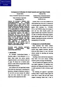
7. Hardware Tests and Simulator Validation This section provides details of how the developed software simulator is validated against the results of a small-scale engine test carried out at one of the Rolls-Royce gas turbine engine test sites. In the validation procedure, a hardware test-bed consisting of a single cluster of seven IEEE 802.11b nodes (SELEX CISP nodes) was first set up and tested on a RollsRoyce’s Gnome engine. The system was configured as a series of star network configurations with the number of sensor nodes (SNs) enabled varying from 1 to 6, all communicating to a single CH. The packet error rate (PER) and bit error rate (BER) are estimated from the engine test results and then incorporated into the simulator to improve the physical module in the simulator. Figure 2 shows the deployment of six sensor nodes (C0, C1, …, C5) mounted onto the engine frame surrounding the surface of the Gnome engine. C0 is at the bottom of the inlet, C1 and C2 are at the back side of the engine, C3 and C4 are at the front side of the engine and C5 is at the bottom of the outlet. C1 and C2 are denoted by dotted line, as they are not visible from the front viewpoint and are out of line-of-sight of other nodes. In all tests, the packet payload length at the IP network layer is 1446 Bytes and, in every second, about 144 data packets in total are generated to simulate the sampling process during engine testing. Each test lasted 15 minutes and is compared with the average of 10 simulations runs. The results of the single sensor node test is used as training data, while all other test results are used for validation. In the single sensor node tests, two IEEE 802.11b compatible SELEX CISP nodes are used as the sensor node (transmitter, C2 in Figure 2) and the cluster head (receivers, not shown in Figure 2), respectively to perform a baseline measurement of the PHY layer performance without multiple access interference from other nodes. Furthermore, in our test-bed, the IP/TCP and application layers do not have a re-transmission scheme or an error correction scheme. The maximum number of transmissions is set to 1 to avoid the impacts of re-transmission, as the main focus of our validation is the PHY layer. More parameters of the test-bed are listed in Table I. Figure 3 shows the data rate (left y-axis) and packet loss (right y-axis) in the single sensor node engine test. These result are also summarized in the third column of Table II which lists the measured performance metrics of the single node engine test in terms of average values of data rate (Mbps) and packet loss (packet per second). For the purpose of bit error rate estimation, in the following analysis, a term ‘traffic load’, measured in ‘packet per second (pkt/s)’, is defined as the number of packets generated and fed into the network in one second. The traffic load is estimated as: (
ata Rate
)
+ Packet loss
(13)
The packet loss rate β is the ratio between packet loss and traffic load. It is calculated as: Packet oss Traffic load
11
(14)
The packet loss rate β calculated from engine tests (the third row in Table II) is approximately 4.8%. However, the preliminary simulation results using the parameters in Table predict that there will be no packet loss in such a single sensor node configuration. This simulation result is not unexpected because, given the transmission power of +17dBm and the relatively small path loss due to the small size of the engine (in a few meters), the receiving signal power is approximately 23dBm and the resulting SNR is over +70dB which is much higher than the required SNR threshold. Therefore, the packet loss due to the noise is nearly zero and no packet loss is observed in simulation. This mismatch between hardware tests and simulation suggested that additional hardware validation was needed to improve the software simulator. As the CISP has a large buffer such that no packet is dropped due to buffer overflow and the higher layers (TCP/IP and above) have no retransmission or error correct scheme, thus, in the single node tests, no packets are lost by the higher layer protocols (i.e. above the PHY layer). Therefore, the packet loss witnessed in these tests must be caused by two factors: (1) Multiple access interference in collision due to MAC protocol; (2) noise and interference at the PHY layer (e.g. thermal noise, environment RF interference, inter-symbol interference (ISI) by multi-path or non-ideal filtering, etc.). However, in our single sensor node configuration, no multiple access interference is present. Furthermore, as analysed in the preceding paragraph, thermal noise would not explain the 4.8% packet loss in the hardware tests. This leaves only the environment RF interference and inter-symbol interference (ISI) by multi-path or non-ideal filtering to explain the packet loss. In order to further identify the reasons for the packet loss in single sensor node, a series of tests were carried out in an anechoic chamber, where the sensor nodes are isolated from environmental RF interference. The anechoic chamber test results of a single sensor node are listed in the last column of Table II, where an average packet loss of about 2 Pkt/s can be seen. This suggests that a packet loss rate β=1.4% exists even in an ideal, RF interference-free, environment. Comparing the difference of the packet loss ratio between engine tests and the anechoic chamber tests, two conclusions can be made: (1) The packet loss caused by the ISI due to multi-path and/or non-ideal filtering is about 1.4%; (2) Both environmental RF interference and ISI due to multi-path contribute to the packet loss in engine tests. It is reasonable to assume that both engine tests and anechoic chamber tests suffers the same ISI induced packet loss, thus the packet loss due to environment RF interference in engine tests is about .
- .
.
.
8. Simulator Improvement In order to improve the simulator to reproduce the results of the real test-bed, an empirical but realistic packet error rate (PER) and bit error rate (BER) are estimated from the hardware test results and incorporated into the simulator. Since the data packets are 72 times longer (1446×8=11568 bits) than the 20 Bytes RTS/CTS/ACK control packets, the packet loss due to failed RTS/CTS/ACK packets is negligible in comparison. For example, given a moderate bit error rate of 1×10⁻⁴, the 12
possibility of RTS/CTS/ACK having a bit error is
(
) (
times less than the possibility of a corrupted DATA
)
packet. It is reasonable to assume an error-free RTS/CTS/ACK transmission in our tests. Given the maximum number of retransmissions at the MAC layer is m, the packet error rate (PER) can be estimated as: P R
√
(15)
Note that, this calculation is only correct when the transmission is collision-free (without multiple access interference), i.e. in single sensor node tests. Since the payload of a DATA packet is 1446×8=11568 bits, the bit error rate is approximately B R
√( -P R)
-
(16)
Substituting m=1 into above equations, the resulting BERs estimated from the engine tests and anechoic chamber tests are about
and
, respectively as detailed in Table II. As the packet error caused by ISI due to non-ideal
filtering in the hardware and/or from multipath is irreducible, increasing transmitted power or improving the receiver noise figure will not reduce the packet loss. Hence, it is reasonable and straightforward to incorporate an additional bit error rate in the simulator to account for these hardware limitations and environmental impacts. Furthermore, from the viewpoint of software simulation, only the total BER is needed in order to approximate experimental results and it is not necessary for the simulator to distinguish between the effect of the ISI and environmental RF interference. This can be easily verified by studying equations (9)-(11). In summary, the simulator is updated by adding an extra B R item α into equations (9)-(11) as follows: ( )
where
( )
(17)
is the new bit error rate to be used for simulation,
is given by equations (9)-(11) depending on the modulation
scheme where α is the BER estimated from the hardware tests. In order to improve the simulator, a new physical layer parameter called **.phy.BER is introduced into the OMNeT++ configuration file so that the BER of the simulator is adjustable to satisfy the engine tests. Note, that because of the introduction of the gateway module in our simulator, the user is also able to adjust the BER to an appropriate value during the simulation. In the simulator core, the SINR-BER model is improved by adding the user specified BER into the mathematically calculated BER. The simulation of single sensor node with an improved BER model gives the average data rate of 1.5Mbps and the packet loss rate of 1.9 packet per second (pps) in the chamber environment and 1.45Mbps data rate and 6.4pps packet loss for the engine test. Comparing this to the results of chamber and engine tests in Table II, it can be seen that a good match between the simulation results and engine test results is achieved which validates the improved simulator.
13
Furthermore, the improved simulator is cross-validated by comparison with hardware tests with multiple sensor nodes. The comparison between the simulation results and the hardware tests are shown in Figure 4, where the number of sensor nodes increases from 2 to 6. Figure 4 shows good agreement between the simulation and hardware tests, with the maximum percentage error being less than 1.7%. For example, for four sensor nodes, both show the same data rate of about 1.4 Mbps distributed evenly over the four nodes. Similarly to the hardware test, these sensors are organised in a single cluster. A good consistency in terms of network throughput between the software simulation results and the hardware test-bed results is achieved which enhance the reality of the software simulator. The validated simulator enables us to estimate the performance of the WIDAGATE wireless network with more confidence. In order to demonstrate how the developed realistic simulator aids the network developer and instrument engineer selecting an appropriate protocol for this application, this section presents an example of the simulation results, where the performance of three protocols (IEEE 802.11b CSMA/CA, the CSMA-based polling and direct polling at the MAC layer) for SN-to-CH communication are compared. The key parameters of the network configuration are listed in Table III. The cluster size denotes the number of sensor nodes in a cluster. The network throughput of CSMA/CA and the proposed polling under various traffic load (measured in cluster sizes) are depicted in Figure 5. The throughput is shown in terms of both how many packets are received by the cluster head in one second and the equivalent payload data throughput (kbps). It can be seen that, at smaller cluster size, the throughput of all three schemes increases linearly with respect to the increasing traffic load but differ at the upper bounds. The CSMA-based polling achieves the upper bound of 150kbps when cluster size is 14. The IEEE 802.11b CSMA achieves the maximum throughput of 275kbps and then decreases when increasing the cluster size further. This shows that the CSMA/CA reaches a saturated condition at 275kbps, which is a drawback of CSMA in high traffic networks. In contrast, the direct polling MAC is capable of 300 kbps (at cluster size of 28) and then stays constant even though the traffic load keeps increasing. This implies that MAC polling is able to double the throughput at moderate and large cluster size compared to the CSMA-based polling. From the point of view of instrumentation engineers, the simulation results suggest that: (1) for a small network with low traffic load (cluster size less than 14), all these protocols have the same throughput performance. Under low traffic load, one iteration of CSMA/CA channel sensing and random back-off is enough to avoid any collisions. Therefore, the performance of contention-based CSMA/CA is similar to the collision-free polling scheme. In terms of development costs and time-tomarket, the IEEE 802.11b is the cheapest and fastest solution, MAC polling is costly and CSMA-based polling could be the trade-off. (2) For a moderate network, the CSMA-based polling fails to meet the throughput requirement. (3) For a large
14
network with cluster size greater than 26, the IEEE 802.11b also fails and the direct polling at MAC is the only choice despite potentially higher product development costs and longer time-to-market. (4) The direct polling MAC also fails when cluster size is greater than 28 and some modifications have to be taken into account to improve the throughput performance. For example, dynamically adjusting the POLL-DATA timeout, or using a multi-polling/multi-ACK scheme (to reduce the overhead of POLL-ACK). Alternatively, some intelligent optimization method may be adopted to optimize the location and polling sequence to improve the throughput. Furthermore, as the polling has a flat throughput when saturated, the polling protocol is more robust than CSMA/CA in industrial applications.
9. CONCLUSIONS In this paper, we present a realistic wireless sensor network simulation platform for industrial applications in harsh environments. In order to increase the accuracy of such a simulator, a realistic radio channel model has been developed from a series of transmission gain measurements taken from an engine site and validated by a series of hardware tests. A good match between the simulation results and the hardware tests demonstrates the effectiveness of the proposed scheme and gives the end-user confidence in the simulation results. Although the proposed simulation platform is developed for data acquisition during gas turbine engine testing, it is a generic modular framework that provides a solid base and framework for simulating wireless networks for industrial applications and can be easily modified for many industrial applications.
ACKNOWLEDGMENTS This research was supported by the WIDAGATE (Wireless Data Acquisition in Gas Turbine Engine Testing) project sponsored by the Technology Strategy Board (TSB) project Gathering Data in Complex Environments and the UK Engineering and Physical Sciences Research Council (EPSRC) under Grants TS/G002614/1 and TS/G002681/1. The Technology Strategy Board is a business-led executive non-departmental public body, established by the government. Its role is to promote and support research into, and development and exploitation of, technology and innovation for the benefit of UK business, in order to increase economic growth and improve the quality of life. It is sponsored by the Department for Business Innovation and Skills (BIS). For further information please visit www.innovateuk.org.
REFERENCES [1] [2] [3] [4] [5]
. Kotz, C. Newport, C. lliott “The Mistaken axioms of wireless-network research”, artmouth College Computer Science Technical Report, TR2003-67 X. Dai, K. Sasloglou, R. Atkinson, J. Strong, I. Panella, L.Y. Cai, H. Mingding, A.C. Wei, I. Glover, J.E. Mitchell, W. Schiffers and P.S. utta “Wireless Communication Networks for Gas Turbine ngine Testing,” International Journal of Distributed Sensor Networks, vol. 2012, no. Article ID 212876, p. 18, 2012. A. Varga, “The OMNeT++ iscrete vent Simulation System,” in Proc. of the European Simulation, 2001. F. Mobility, [online] http://mobility-fw.sourceforge.net/, Jan 2007. [Online]. Available: http://mobilityfw.sourceforge.net/ National ICT Australia td, “Castalia,” [online] http://castalia.npc.nicta.com.au, National ICT Australia. 15
[6] MiXiM, “Mixim (mixed simulator) project,” [online] http://mixim.sourceforge.net, 2010. [7] A. Kopke, M. Swigulski, K. Wessel, and D. Willkomm, “Simulating Wireless and Mobile Networks in OMN T++ –the mixim vision,” in Proc. of 1st International Workshop on OMNeT++, Mar 2008. [8] Zigbee-Alliance, “Zigbee Specification,” Tech. Rep., 2005. [Online]. Available: http://www.zigbee.org/ [9] K. Sasloglou, I. Glover, and P. utta, “ mpirical Modelling and Simulation of Transmission oss Between Wireless Sensor Nodes in Gas Turbine ngines,” in Proc. 7th Int. Conf. in Information, Communications and Signal Processing (ICICS 2009), 2009. [10] Eurocae ed- e, “A joint UROCA RTCA Achievement [sections 9-2 ],” The uropean Organisation for Civil Aviation Equipment, Tech. Rep., March 2005. [11] P. Omiyi, K. Bür, and Y. Yang, “ istributed Convergecast Scheduling for Reduced Interference in Wireless Sensor and Actuator Networks,” in Proc. IEEE Wireless Communications and Networking Conference (WCNS’10), pp. 1–5, 2010 [12] Hashmi, S.U.; Mouftah, H.T.; Georganas, N.D., Achieving Reliability Over Cluster-Based Wireless Sensor Networks Using Backup Cluster Heads, IEEE GLOBECOM '07, pp.1149-1153, 26-30 Nov. 2007
[13] U. M. Colesanti, C. Crociani, and A. Vitaletti, “On the accuracy of OMNeT++ in the wireless sensor networks domain: simulation vs. testbed,” in Proceedings of the 4th ACM workshop on Performance evaluation of wireless AdHoc, sensor, and ubiquitous networks, New York, USA 2007, pp. 25–31. [14] G. P. Halkes and K. G. angendoen, “ xperimental evaluation of simulation abstractions for wireless sensor network MAC protocols,” EURASIP Journal on Wireless Communication Networks, vol. 2010, pp. 1–10, 2010 [15] L. Bergamini, C. Crociani, A. Vitaletti, and M. Nati, “Validation of wsn simulators through a comparison with a real testbed,” in Proceedings of the 7th ACM workshop on Performance evaluation of wireless ad hoc, sensor, and ubiquitous networks, New York, USA, 2010, pp. 103–104. [16] M. Bredel and M. Bergner, “On the accuracy of IEEE 802.11g wireless lan simulations using OMNeT++,” in Proceedings of the 2nd International Conference on Simulation Tools and Techniques, Brussels, Belgium, 2009, pp. 1– 5. [17] E. Kolega, V. Vescoukis, and D. Voutos, “Assessment of network simulators for real world wsns in forest environments,” in 2011 IEEE International Conference on Networking, Sensing and Control (ICNSC), 2011, pp. 427 – 432.
16
Figure Captions Figure 1: Cluster tree topology Figure 2: Deployment of the SELEX CISP nodes on the Gnome engine Figure 3 Data rate and packet loss of the single sensor node engine test Figure 4 Summary of data rate in simulation and hardware tests
Table Captions Table I Common parameters of the engine tests Table II Measured and estimated parameters at engine tests and anechoic chamber tests Table III Key parameters of network configuration
17
Figure 1
18
Figure 2
19
Figure 3
20
Figure 4
21
Figure 5
Figure 1 Throughput of CSMA/CA and polling
22
Table I
Parameters Physical data rate SNR threshold Transmission Power Antenna gain
Values 2 Mbps 3dB +17dBm 2dB
23
Table II
Measured parameters
Estimated parameters
Parameters Number of sensor nodes Data rate (Mbps) Packet loss (Pkt/s) Packet payload (Byte) Maximum MAC retransmission m Valid traffic (Pkt/s) Estimated Traffic load (Pkt/s) Packet loss ratio PER estimate (m=1) BER estimate
24
Engine Tests 1 1.45 6.33 1446 1 125.35 131.68 4.81% 0.0481 -6 4.26 x 10
Chamber Tests
1 1.500 1.9 1446 1
129.67 131.57 1.44% 0.0144 -6 1.26 x 10
Table III Common parameters Cluster size {5,6,…, 0} Sampling interval 0.03s DATA packet Payload 40 Bytes POLL/ACK packet length 38 Bytes Parameters of PHY layer (802.11b DSSS, DQPSK, long preamble) Data rate at PHY layer 2 Mbps Transmission power 20 dBm Noise bandwidth 22 MHz Parameters of Polling at MAC layer POLL-DATA timeout 1.5ms Parameters of Polling at APP layer POLL-DATA timeout
10 ms
25