2009 IEEE International Conference on Robotics and Automation Kobe International Conference Center Kobe, Japan, May 12-17, 2009
Development of a 2-DOF Electrostatic Haptic Joystick for MRI/fMRI Applications Masayuki Hara, Member, IEEE, Gaëtan Matthey, Akio Yamamoto, Member, IEEE, Dominique Chapuis, Student Member, IEEE, Roger Gassert, Member, IEEE, Hannes Bleuler, Member, IEEE, and Toshiro Higuchi, Member, IEEE
Abstract—This paper describes the development of a 2-DOF electrostatic haptic joystick designed for neuroscience studies in an MRI/fMRI. The joystick is fabricated using non-magnetic materials and actuated by two high-power electrostatic motor units which produce various force fields in the horizontal plane. The electrostatic motor is a synchronous drive and thus the positioning of the joystick is achieved in an open-loop control. As for force sensing, a 2-DOF force sensor is developed using non-magnetic materials and optical fibers so as to measure interaction force with a user; hence, the haptic rendering is based on the admittance control scheme that respects the rule of force-in and position-out. The operation of both the actuators and force sensor respects non-magnetic principles. Thus, the haptic joystick into which these components are integrated is expected to have high MR compatibility, although the evaluation of the MR compatibility is beyond the scope of this paper. In this paper, the device performance is evaluated in the normal environment, which verifies the operation of the unique electrostatic haptic device.
T
I. INTRODUCTION
HE investigation of upper limb movements has a long history, and several researchers have attempted to reveal the underlying principles [1–3]. Recent studies have focused on human reaching movement and attempted to develop a human motor control model from an optimization viewpoint. For example, Flash and Hogan showed that the path from a start to the goal is planned to minimize the jerk—derivative of acceleration—at the hand [4] and proposed the minimum jerk model [5]. Based on this model, some motor control models, such as the minimum torque-change model and minimum muscle-tensile-force-change, have been proposed and discussed [6] [7]. In these studies, a manipulandum, which comprises a parallel-link mechanism and direct-drive motors, is often employed to produce various force fields, under which the trajectory of the hand motion is measured [8]. The use of a manipulandum or haptic device facilitates the analysis of reaching movement. Focusing on the trend of this Manuscript received September 15, 2008. This work was supported in part by a Grant-in-Aid for Scientific Research on Priority Areas (No. 16078203) from MEXT of Japan. M. Hara, A. Yamamoto, and T. Higuchi are with Dept. of Precision Engineering, School of Engineering, The University of Tokyo, Tokyo, 113-8656 Japan (phone: +81-3-5821-6466, e-mail:
[email protected] [email protected],
[email protected]). G. Matthey, D. Chapuis, R. Gassert, and H. Bleuler are with Ecole Polytechnique Fédérale de Lausanne, Lausanne, 1015 Switzerland (e-mail:
[email protected],
[email protected],
[email protected],
[email protected]).
978-1-4244-2789-5/09/$25.00 ©2009 IEEE
research, the subject of studies on sensorimotor function seems to be shifting from human body function to brain function, as described in the report by Gomi et al [9]. Recently, functional magnetic resonance imaging (fMRI) has been focused on as a powerful tool to investigate human brain functions [10]. Hence, it should be noted that fMRI is effective for investigating brain activities during reaching movement [11] [12]. However, a conventional haptic device cannot be brought into the MR environment as it is [13]. Since a magnetic resonance (MR) scanner utilizes a very strong and precise magnetic field, switching gradient fields and RF pulses for the imaging, devices with electromagnetic factors, such as standard electromagnetic motors, can disturb the precise magnetic field created by the scanner and pose a safety hazard. In addition, the operation of such devices can be disturbed by the strong magnetic field. Those devices are not MR-compatible. Hence, developments of MR-compatible haptic devices are strongly required for brain studies. Some recent studies have reported on fabrication of MR-compatible haptic devices using non-magnetic actuators [14-16]. For example, Izawa et al. developed an MR-compatible manipulandum using ultrasonic motors and proposed an impedance control scheme based on torque control [16]. In those reported studies, ultrasonic motors or hydraulic drives predominate as the actuators for MR-compatible devices. However, there still remain many difficulties, especially, in the control of those actuators due to, e.g., non-linear characteristics or control latency which are inherent to those actuators. This study focuses on another non-magnetic actuator—a high power electrostatic motor—in order to provide a breakthrough for the abovementioned problems. Since the electrostatic motor is a kind of synchronous motor like stepper motors, which facilitates open-loop position/velocity control, the design of the control system should be much easier compared to those of the ultrasonic motor and the hydraulic drive. Our previous study already revealed that the electrostatic motor is MR-compatible [17]. Hence, it is expected that these characteristics enable to create well-controlled and -stabilized virtual dynamics during MRI/fMRI. Considering these advantages, the electrostatic motor seems promising for MR-compatible haptic devices [18], but the application has not been extensively studied in the past. This paper reports a trial to develop a 2-DOF joystick-type haptic device using the electrostatic motor. For
1479
the development, a new configuration of the electrostatic motor is proposed and a 2-DOF fiber-optical force sensor with high MR compatibility is developed for the integration with the electrostatic motor. This paper focuses on the development of the haptic joystick, including the motor unit and the force sensor, and performance analysis in the normal environment; the integrated haptic device is expected to be MR-compatible, but the evaluation thereof is beyond the scope of this paper. We totally present a framework for constructing haptic devices by using the electrostatic motor.
Fig. 3. Arrangement of slider and stator boards. TABLE I PERFORMANCES OF ELECTROSTATIC MOTOR UNITS
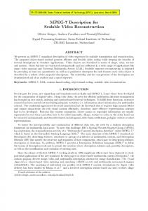
II. ELECTROSTATIC MOTOR A. Driving Principle and Characteristics Fig. 1 illustrates the basic structure of the electrostatic motor, which is called Dual Excitation Multiphase Electrostatic Drive [19]. The motor comprises a pair of boards, which function as a slider and a stator. In a board, three-phase skewed electrodes [20] are allocated at an interval of 200 μm. Between the boards, a myriad of glass beads with 20 μm in diameter are disseminated to reduce the friction. The actuator is driven by application of high-voltage three-phase AC, such as 1.0 to 3.0 kV0-p. A pair of boards can generate approximately 3.5 N at the voltage of 2.4 kV. Since such high voltage has large possibility to cause discharge of surrounding air, the motors should be immersed in dielectric liquid to avoid the discharge. Fig. 2 shows a schematic illustrating the driving principle. Traveling voltage distributions are produced on both the stator and the slider by applying three-phase sinusoidal voltages, as shown in Fig. 2. The electrostatic interaction enables the slider to move so as to maintain the relative position between two traveling waves; the slider moves at a speed proportional to the frequency difference between the stator’s and slider’s three-phase voltages. The synchronous
Fig. 1. Basic structure of the electrostatic motor.
Fig. 2. Driving principle of the electrostatic motor.
Mass in movement Maximum acceleration Friction force Output force at 2.0 kV Output force at 2.2 kV Output force at 2.4 kV
Motor 1 284 g 30.29 m/s2 1.0 N 10.0 N 13.0 N 18.0 N
Motor 2 284 g 30.29 m/s2 0.8 N 10.0 N 13.0 N 18.0 N
velocity of slider, us, can be expressed as u s = 6 pf
(1)
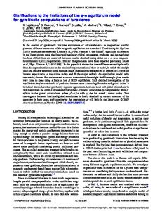
where p and f indicate the electrode pitch and the frequency of the applied AC voltage, respectively. For this reason, electrostatic motors are considered as a synchronous motor like a stepper motor. B. Electrostatic Motor Unit For practical application, several pairs of electrode boards should be integrated to comprise one motor unit. A new configuration for the integration is proposed in this paper to realize more compact and effective structure. The new configuration is shown in Fig. 3. In the case of one-sided pair, the force generation capability changes as the slider moves, since the capability is proportional to the interfacing area of the stator and the slider [18]. In our new structure, two different sets of the stator and the slider boards are allocated so as to compensate this change of the interfacing area. This structure also enables longer motor stroke and larger force. In this study, four pairs are stacked in each set (which means eight pairs were used in total) to generate over 10 N thrust force at 2.4 kV; the maximum forces generated in some voltage conditions are listed in Table I. A developed prototype motor unit is shown in Fig. 4. The complete actuator is enclosed in an acrylic housing and a vinyl sheet cover. Inside the housing is filled with dielectric liquid, Fluorinert FC-77 (3M), to avoid the electric discharges. The sliding part is put on a non-magnetic linear guide made of ceramics for smooth actuation. Two electrostatic motor units with the same structure were fabricated to realize the 2-DOF haptic joystick. Table I lists the basic performances of the two motors. Most specs, except for friction force, are the same. The friction force characteristics might have been affected by the vinyl sheets
1480
Fig. 5. Structure of the elastic probe.
Fig. 4. Structure of the prototype electrostatic motor unit.
that were used to avoid evaporation of the dielectric liquid. As listed in Table I, the proposed electrostatic motor unit excels in the back drivability (less friction) and can relatively generate larger force. These imply that it is easier to make a well-stabilized virtual dynamics. Hence, it should be noted that the developed motor units realize relatively high performances compared to other non-magnetic motors like commercial ultrasonic motor used in reference [16].
Fig. 6. Measurement principle of the optical displacement sensor: the deflection of an elastic probe is detected by reflected light intensity measurement over optical fibers.
III. MR-COMPATIBLE FORCE SENSOR A. Design Concept In general, an MR compatibility for sensors implies that the sensor should be able to work in an environment with very high magnetic field and must not disturb MR images. This indicates that the following points should be strictly followed: 1) Do not deform the magnetic field 2) Do not emit radio waves in the reception bandwidth of the scanner 3) Do not pose a safety hazard Respecting these points, we designed and developed an MR-compatible 2-DOF force sensor for the haptic joystick. The details are presented in the following sections. B. Design of 2-DOF Fiber-Optical Force Sensor Force sensors generally utilize strain gauges. In those sensors, the interaction force is calculated from the strain measured when an external force is applied to a base material. However, a standard strain gauge cannot be taken in MR room due to interference with the magnetic field and the RF pulse emitted by the scanner. Shielded strain gauges were also tested in MR environments [21], but some problems such as the influence of RF pulse still remain. In this work, we attempted to utilize optical displacement sensors to measure the deformation of an elastic probe under application of an external force instead of strain gauges [22]; the employed optical sensor was FUE200C1004 of Baumer Electric. Figs. 5
Fig. 7. Prototype 2-DOF fiber-optical force sensor.
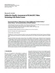
and 6 show the basic structure and the measurement principle, respectively. The merit of this approach is that all electronic components, which have possibility to affect the MRI/fMRI, can be located outside the MR room. Figs. 7 and 8 show an appearance of 2-DOF fiber-optical force sensor integrated with a handle and a schematic diagram of its inner structure, respectively. The frame components are basically made of carbon fiber and its dimensions are determined based on an analysis from a view point of material mechanics [22], and are outside the scope of this paper. As shown in Fig. 8, two mirrors are attached to the lower part of a mobile part (upper plate). In an optical head, light from an optical fiber is irradiated on these mirrors and the reflected light is received by the other optical fiber. Since the mobile part is attached to the fixed base over carbon fiber blades, it can be slightly displaced in a horizontal direction when an
1481
TABLE II PERFORMANCES OF THE FIBER-OPTICAL FORCE SENSOR
Resolution Linearity Hysteresis Stiffness Resonance peak
Axis 1 up to 0.08 N 2.09% 4.08% 29.14 N/mm 140 Hz
Axis 2 up to 0.08 N 3.18% 6.34% 27.93 N/mm 121 Hz
Fig. 8. Inner structure of the developed 2-DOF fiber-optical force sensor.
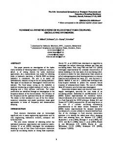
(a) Bode diagram of Axis 1
Fig. 9. Experimental setup for characterization.
external force is applied. Following this displacement, the central beam of force sensor is also displaced in the horizontal direction. This result in an intensity change of the reflected beam carried through the optical fiber. Hence, the applied force can be measured by reading the change of light intensity. Finally, the optical signal is converted to an electrical signal via an analog amplifier (model: FWDK10U840Y0, Baumer). C. Force Sensor Characterization The characteristics of the developed sensor were investigated by using an experimental setup shown in Fig. 9. The setup consists of a 1-DOF reference load cell which is placed on a linear guide and a laser displacement meter. Since the linear guide can be moved by turning a micrometer screw, it is possible to apply forces when both sensors are in contact. On the other hand, the optical displacement meter also measures the travel distance of the linear guide. By using this experimental setup, we investigated the static characteristics of the fiber-optical force sensor: resolution, linearity, hysteresis, and stiffness. Those specifications are listed in Table II. It should be noted that there are linearity error ranged from about 4 to 6% and hysteresis ranged from about
(b) Bode diagram of Axis 2 Fig. 10. Frequency responses of the fiber-optical force sensor.
2 to 3%. The stiffness of the force sensor is approximately 28 to 29 N/mm. A dynamic performance was investigated through pseudo-impact response of the sensor. Fig. 10 shows the estimated frequency response. Approximately, a bandwidth of 100 Hz is obtained for each axis although there exists a resonance, which should be eliminated electrically. This bandwidth is a little bit lower than a 1 kHz bandwidth generally required for the haptic rendering, but the developed fiber-optical force sensor has no doubt that it has a high MR compatibility and a tremendous potential for MRI/fMRI related studies; improving the bandwidth is an assignment in our future study.
1482
Fig. 11. Overview haptic joystick.
Fig. 12. Schematic diagram of haptic joystick system.
Virtual dynamics
+
− +
fd
+
1/m
&x&d
1/s
x& d
xd
1/s
Electrostatic motor1
×1000
Electrostatic motor2
D Damper Signal generator
K
f
×1000
Mass
High-voltage amplif ier
Spring Force sensor Fig. 13. Block diagram of the admittance controller.
IV. 2-DOF HAPTIC JOYSTICK A. System Architecture A 2-DOF joystick-type haptic device (haptic joystick) was fabricated by integrating the electrostatic motor units and the fiber-optical force sensor, which can be operated like the manipulandum in a horizontal plane. Fig. 11 shows a picture of the final assembly. Two electrostatic motor units are orthogonally arranged, as shown in Fig. 11. An acrylic stage on two ceramic linear guides, which are normal to each other along X and Y axes, is arranged between the electrostatic motor units and moves in conjunction with the movements of the two motors. On the stage, the fiber-optical force sensor with a handle is fixed. The workspace is about 40 mm × 40 mm, but this is not so narrow compared to the other similar MR-compatible haptic device [16]; expanding the workspace is possible by using the longer electrostatic films and ceramic linear guides. After the final assembling, the force display performances are still almost the same as Table I. B. Application of Admittance Control Fig. 12 indicates a schematic diagram of the haptic joystick
system. In this system, all I/O controls are performed by a DSP system; the I/O data, such as output voltage and force data, are exchanged through a DSP I/O board (model: DS1104, dSPACE) connected with a computer for monitoring. The control program is created with MATLAB/Simulink. The 3D visual rendering is done on another computer, to which the position data of the joystick is sent from a D/A port of DSP I/O board to an external A/D converter (model: USB-ADC-11/12, PICO technology). Haptic interfaces are typically operated using one of two control modes—impedance control and admittance control [23] [24]. In this work, we applied an admittance control with open-loop positioning [18]. Fig. 13 illustrates a schematic block diagram of the applied admittance control; in Fig. 13, M , D, K ∈ R 2×1 indicate inertia, viscosity, and stiffness parameters, respectively. The admittance control needs to measure the interaction force and to calculate velocity or position based on the internal virtual dynamics. In our case, the controller receives the interaction force measured by the fiber-optical force sensor and calculates the positions which the device should follow. Based on the calculated position, three-phase voltages, vstator , vslider ∈ R1×3 , for driving motor
1483
[3] [4]
[5]
[6]
Fig. 14. Sample haptic application.
are calculated as
[7]
φstator = 20πt
(2)
φslider = 20πt + 2πx d / 3 p
v stator = v 0 [sin (φstator ) sin (φstator −
) 2 π v slider = v 0 [sin (φslider ) sin (φslider − 3 ) 2π
3
)] 2 π sin (φslide r + 3 )] sin (φstator +
2π
3
(3) (4)
[8] [9]
(5) [10]
where t represents time. The calculated three-phase voltages are fed to high-voltage amplifiers and then provided to the electrostatic motors. A simple application is made together with the visual display, as shown in Fig. 14, in which the virtual dynamics can be changed during a line-trace movement. Some users tried it under some dynamics conditions in normal environment and subjectively gave good feedbacks; to identify it, the quantitative evaluation is required in future. V. CONCLUSIONS A 2-DOF haptic joystick with force feedback has been developed considering its application for MRI/fMRI studies. High-power electrostatic motors and a force sensor based on optical displacement sensing were utilized so as to achieve MR compatibility. The developed motor unit is highly back drivable and the maximum force output was 18 N at 2.4 kV, providing better performance in comparison to the commercial ultrasonic motor. A fiber-optical force sensor considering MR compatibility was also fabricated and its sensing performance was characterized. According to the characterization, it was verified that the developed force sensor has approximately 100 Hz bandwidth. Using the integrated device, a simple haptic rendering was achieved based on an admittance control; the rendering performance of virtual dynamics was subjectively perceived to be good. All the experimental results described in this paper are limited to a normal environment. Our future study will bring the haptic joystick into an MR room to test the MR compatibility. REFERENCES [1]
[2]
[11] [12] [13] [14]
[15] [16] [17] [18] [19] [20] [21]
[22] [23]
R. Plamondon and A.M. Alimi, “Speed/accuracy trade-offs in target-directed movements,” Behavioral and Brain Science, vol. 20, 1997, pp. 279-349. D. Elliott, G. Binsted, and M. Heath, “The control of goal-directed limb
[24]
1484
movements: Correcting errors in the trajectory,” Human Movement Science, vol. 18, 1999, pp. 121-136. R.A. Woodworth, “The accuracy of voluntary movement,” Psychological Review, vol. 3, 1889, pp. 1-119. N. Hogan, “An organizing principle for a class of voluntary movements,” The Journal of Neuroscience, vol. 4, 1984, pp. 2745-2754. T. Flash and N. Hogan, “The coordination of arm movements: an experimentally confirmed mathematical model,” The Journal of Neuroscience, vol. 5, no. 7, 1985, pp.1688-1703. Y. Uno, M. Kawato, and R. Suzuki, “Formation and contour of optimal trajectory in human multijoint arm movement–minimum torque-change model,” Biological Cybernetics, vol. 61, 1989, pp. 89-101. M. Kawato, “Computational theory of human brain,” Sangyou-tosho, 1995. (in Japanese) H. Gomi and M. Kawato, “Equilibrium-Point Control Hypothesis Examined by Measured Arm Stiffness During Multijoint Movement,” Science, vol. 207, no. 5258, 1996, pp. 117-120. H. Gomi, N. Abekawa, and S. Nishida, “Spatiotemporal Tuning of Rapid Interactions between Visual-Motion Analysis and Reaching Movement,” The Journal of Neuroscience, vol. 26 no. 20, 2006, pp. 5301-5308. D.J. Heeger and D. Ress, “What does the fMRI tell us about neuronal activity?”, Nature Reviews Neuroscience, vol. 3, 2002, pp. 142-151 E. Burdet, R. Osu, D.W. Franklin, T. E. Milner, and M. Kawato, “The CNS stabilizes unstable dynamics by learning optimal impedance”, Nature, vol. 414, 2001, pp. 446-449. R. Moser, R. Gassert, E. Burdet, L. Sache, H. R. Woodtli, J. Eri, W. Maeder and H. Bleuler, “An MR compatible robot technology”, Proc. ICRA’03, pp. 670-675. K. Chinzei, R. Kikinis and F.A. Jolesz, “MR compatibility of mechatronic devices: design criteria,” Proc. MICCAI, 1999, pp. 1020-1030. R. Riner, T. Villfrantener, R. Kleiser, T. Nef, and S. Kollias, “fMRI-Compatible Electromagnetic Haptic Interface,” Proc. of IEEE-EMBS 2005, the 27th Annual International Conference, 2005, pp. 7024-7027. J. Citérin and A. Kheddar, “An MRI-compatible tactile display device based on IPN-CP pastille-shaped actuators,” Proc. of SPIE, vol. 6168, 2006, pp. 365-376. J. Izawa, T. Shimizu, H. Gomi, S, Toyama and K. “MR compatible manipulandum with ultrasonic motor for fMRI studies,” Proc. of ICRA’06, 2006, pp. 3850-3854. A. Yamamoto, K. Ichiyanagi, T. Higuchi, H. Imamizu, R. Gassert, M. Ingold, L. Sache, and H. Bleuler, “Evaluation of MR-compatibility of Electrostatic Linear Motor,” Proc. of ICRA’05, 2005, pp. 3669-3674. A. Yamamoto, Y. Hirano, K. Ichiyanagi, and T. Higuchi, “Development of a 1-DOF Haptic Device Using an Electrostatic Film Motor for fMRI Studies,” Proc. of ICRA’06, 2006, pp. 4378-4380. T. Niino, T. Higuchi, S. Egawa, “Dual Excitation Multiphase Electrostatic Drive,” Conf. Record of 1995 IEEE IAS annual meeting, 1995, pp. 1318-1325 A. Yamamoto, T. Niino, and T. Higuchi, “Modeling and Identification of an Electrostatic Motor,” Precision Engineering, vol. 30, no. 1, 2006, pp. 104-113 M. Rajendra, A. Yamamoto, T. Oda, H. Kataoka, H. Yokota, R. Himeno, and T. Higuchi, “Motion Generation in MR Environment Using Electrostatic Film Motor for Motion-Triggered Cine-MRI,” IEEE/ASME Trans. on Mechatoronics, vol. 13, no. 3, 2008, pp. 278-285. R. Gassert, D. Chapuis, H. Bleuler, and E. Burdet, “Sensors for Applications in Magnetic Resonance Environments,” IEEE/ASME Trans. on Mechatronics, vol. 13, no.3, 2008, pp. 335–344. Y. Yokokohji, R. Hollis, and T. Kanade, “What you can see is what you can feel – development of a visual/haptic interface to virtual environment,” Proc. of VRAIS’96, 1996, pp. 46-53. K. Salisbury, F. Conti, and F. Barbagli, “Haptic Rendering: Introductory Concepts,” IEEE Computer Graphics and Applications, vol. 24, no. 2, 2004, pp. 24-32.