DEVELOPMENT OF A ROBOTIC MEASURING SYSTEM FOR 3D RANGE DATA ACQUISITION Tien-Fu Lu and Jingsyan Torng Mechanical Engineering Deparrtment, Adelaide University, Australia K. C. Fan Mechanical Engineering Department, National Taiwan University, Taiwan
[email protected]
Abstract In automated factories, industrial robots have been utilised in various kinds of applications, such as material handling, painting, welding and assembling. A novel application of robot in metrology has been presented in this research. This paper presents the development of a robotic measuring system for 3D range data acquisition, which consists of an industrial robot, a set of stereo CCD camera, multiple laser stripes and a personal computer. Topics such as robot calibration, camera calibration, measuring methodologies, and surface connection and registration will be addressed in the paper. Keywords: Robot, Calibration, Stereo CCD Camera, Multiple Laser Stripes, 3D Data Acquisition
Introduction Robot arms are versatile, flexible and widely used in manufacturing industries for various applications such as material handling, painting, welding and assembly. However, it is known that robots have better repeatability than positioning accuracy. Normally robot repeatability accuracy is about 0.1 to 0.2 mm but the positioning inaccuracy may be up to 20 mm or even more if not properly calibrated. Therefore, due to the limitation of robot positioning accuracy, metrology is one field that hardly utilises industrial robots to perform measurement tasks. Large object measurements in metrology are always difficult and very expensive to automate. The main reason is that most large objects are bigger than the working envelope of measuring machines. Although there are large-scale measuring machines and other specialized measuring devices existed for large object measurement in the market, the cost is nevertheless too high. For medium- to large-sized objects such as metal sheets of car body, medium to large-sized molds or stamping metal parts, the accuracy requirement is not as strict as for small machine parts. Realistically, 1 or 2 mm accuracy for stamping metal sheet of car body is considered to be Development of a robotic measuring system for 3d range data acquisition
1
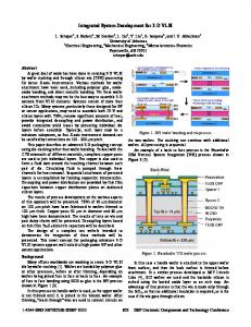
sufficient when the car production people in the top automotive manufacturing companies such as General Motors, Ford and Chrysler are talking about making the “2-mm-car” or the future “1mm-car”. Therefore, applying industrial robots with image data acquisition devices for mediu- to large-sized object metrology is practical and feasible. Unlike the Coordinate Measuring Machine (CMM), robot has six jointed arms and its geometry constraints have resulted in diverse measuring trajectories and strategies. CCD camera is an image device that can easily capture 2D image information. A set of stereo CCD camera, like human’s eyes, with a multiple laser stripe projector that can obtain the 3D information of the measured surfaces. The integration of a robot and a set of stereo CCD camera with the laser stripes that offer a workbench for non-contact 3D image data acquisition is shown in Figure 1.. In this system, robot calibration, camera calibration, measuring methodologies and surface connection technique are the main processes in this study. P2 P3 Stereo CCD
P1 Laser Stripes
P5
x
Workpiece
z
P4 LDS Industrial Robot
Figure 1. System Construction
y Laser Ballbar
Robot Reference Frame
Figure 2. Robot calibrated by 3D Laser Ballbar
Robot Calibration Industrial robot needs to be calibrated before it can be used in metrology. Robot repeatability can normally reach 0.1 mm but robot positioning accuracy is so far behind the allowance of manufacturing acceptance which may approach 10 to 20 mm. Therefore, accuracy calibration appears to be the major issue for a robotic measuring system. There are many kinds of methodologies being developed for robot calibration such as theodoilite, ultrasound and laser tracking [1,2,3]. Most of the systems are too expensive or have low resolution. A 3D Laser ball bar developed by Precision Metrology Laboratory, National Taiwan University, is applied in this research [4]. This new developed laser coordinate measuring instrument which includes an extension bar and a laser emitter and receiver with a reflector that can offer an accurate world coordination measurement. After calibration, a robot accurate positioning database can be established and it can supply the information for accurate robot positional compensation. Robot positioning calibration is the main process before it can be Development of a robotic measuring system for 3d range data acquisition
2
utilised in metrology. According the developing processes, the 3D laser ball bar has to be calibrated by a CMM or CNC machine that can ensure to obtain the micro-meter level accuracy. ISO 9238, the robot calibration standard [5], provided the calibration procedures in this research. According to ISO 9238, the calibrated robot needs to move repeatedly to five explicitly defined testing points and to measure the deviation of positioning accuracy and repeatability errors. The positions of the testing points are defined in the ISO documentary which is shown in Figure 2. The overall calibration system is also illustrated in Figure 2 that includes a 3D Laser Ballbar and an industrial robot. Robot moved from position P1 to P5 for five times surround the measuring workspace, the calibrated results are recorded and plotted in Figure 3 and Figure 4. The maximum standard deviation of repeatability is 0.095mm and the maximum positioning inaccuracy is 0.57mm. Those data can be used for robot spatial position compensation.
R o b o t R e p e a ta b ility
R o b o t P o s ito n in g E rro rs Error (mm)
Errors (mm)
0 .8 0 .6 0 .4 0 .2 0 1
2
3
4
0 .1 0 .0 8 0 .0 6 0 .0 4 0 .0 2 0 1
5
Figure 3. Robot Positioning Accuracy
2
3
4
5
C a lib ra tio n P o in t
C a l ib r a t i o n P o i n t
Figure 4. Robot Repeatability Accuracy
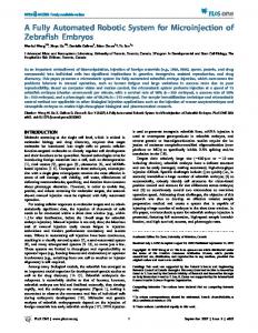
Camera Calibration Since CCD camera is an optical device which combines optical lenses and image capturing devices. Because of the physical characteristics, optical lens can always result in the distortion of captured images. Therefore, camera calibration is another important issue of this application. The CCD image is a two-dimensional vision data. While 3D vision measurement, 2D image’s pixel points must to be converted into 3D world coordinates data, in other words, the relationship between CCD image coordinates and world coordinates needs to be established, and finally to calculate the 3D results. A V-shape block is prepared for camera calibration and converting 2D image data into 3 D world coordinate data. The V-shape block was firstly measured by a CMM to ensure an accurate dimensional range for calibration. The two calibration planes of V-shape block are computed by Least-Square methodology to obtain two plane equations.
Development of a robotic measuring system for 3d range data acquisition
3
Figure 5. V-shape Block with Surface Grids for Camera Calibration (Left CCD Image)
Figure 6. V-shape Block with Laser Stripes for Laser Planes Calculation (Right CCD Image)
For a 2D image, as in Figure 5, the surface grids are then calculated to fit two plane equations in order to convert 2D image data into 3D world coordinate data. In Figure 6, laser projector is emitted and imposed laser stripes on two calibration planes. Each laser stripe can be regarded as a laser plane emitting from the laser projector and giving the source of information to acquire 3D measuring data when it is projecting on the measured object. Simultaneously, left and right CCD cameras need to be calibrated before they are used as measuring devices. While one CCD camera is not able to offer enough information, such as the case of broken lines and shading, the other CCD camera can then supply the information to perform a complete 3D object world coordinate data acquisition. The resolution of CCD cameras can easily be acquired by dividing the dimension of V-shape block with image pixel number. In our system, the resolution is around +/0.17 mm. Measuring Methodology To apply 3D image measurement in a large object will always encounter a problem of the size of the measured object. If the measured object is much larger than the image range, then the measuring strategies and surface connection techniques will need to be developed in this application. In the research, the measured object’s surface profile needs to be clarified before it can develop the measuring strategies. In this image measuring robot system, the laser projector is mounted on between two CCD cameras and the multiple laser stripes are imposed on the measured surfaces. CCD cameras capture laser stripes’ images and offer information for calculating 3D surface coordination data. Actually, when CCD cameras approach the measured object, an object image can be obtained. Practically, by calculating the gap between two adjacent stripes’ image with triangulation method and comparing with the next position’s image, after feedback vision-servo control procedure, can obtain the same approaching distance to the surface in that two position. To use the same concept, calculating the angles between the central laser plane and two adjacent planes, the surface normal can be computed. Once the surface normal of each measured position being found, the robot moving trajectory can be easily planned. Basically, measuring trajectory planning needs to consider the measured image overlap area. The image overlap area is the area that two neighbouring images partly cover by each other. It can ensure that two adjacent measured images have no missing data and ease to supply data Development of a robotic measuring system for 3d range data acquisition
4
information for surface registration. The robot will record the position of each movement and automatically add the shifting displacement on the measured surfaces’ data to form a complete shape.
Surface Registration Measured surfaces’ image data needs to be connected in order to form a complete data cloud. Firstly, the normal vector of each cloud point in registration area has to be found before processing surface connection. Secondly, from calculating the correspondent normal vectors on two surfaces being connected, the rotating angle and translating distance can be calculated. Finally, translating and rotating the coordinate match the first surface data. Presently, there exists some commercial software in the market to process measured data points. In this research, the software DigiPoly, developed by Chitai Co., is applied to manage the measured surfaces’ data. Figure 7 and 8 are shown a free form surface before registration and after registration process.
Figure 7. Free-form Surface before Registration
Figure 8. Free-form Surface after Registration
Conclusion Industrial robot with six degree of freedom has more flexibility than any other devices in automated factories. After proper calibration, robot is able to be applied in metrology. Visual measurement is a non-contactable measuring methodology for 3D data acquisition. Stereo camera with multiple laser stripes can supply the information for converting data from 2D image coordinate to 3D world coordinate. Comparing with a single laser stripe, multiple laser stripes visual measurement do not need to rotate the measured object which may appear difficulty in rotating a large-sized object. Meanwhile, it is able to offer a speedy way for obtaining more data information in each image capturing. The robotic measuring system has to move to different positions to acquire the measured data for surface connection in order to form a complete feature. Robot controller, at this stage, can offer the spatial coordinate of each movement and add to the measured data coordinate for surface connection. With the success of surface connection and registration, 3D surface data of a complete object can be obtained. This investigation has shown Development of a robotic measuring system for 3d range data acquisition
5
the methodology of 3D range data acquisition for medium- to large-sized objects through the robotic measuring system.
Reference [1] Torng, J.; Ferris, T.L.J. and Lin, G.C.I. “Design of Accurate Measurement System for Robot Position Calibration”, Proceedings of the 2000 Pacific Conference on Manufacturing (PCM'2000), 6-8 Sep 2000, Southfield-Detroit, Michigan, USA, Volume 2, pp782-pp787. [2] Torng, J.; Lin, G.C.I.; Lu, T.F. and Ferris, T.L.J. “Development of An Automated Coordinate Measuring Robot (CMR) for Large Objects Measurement”, Proceedings of the 5th International Conference on Computer Integrated Manufacturing, 28-30 March 2000, Singapore, pp 415-424. [3] Rocadas, P. S. ; McMaster, R. S. ;A robot cell calibration algorithm and its use with a 3D measuring system; ISIE '97.Proceedings of the IEEE International Symposium on Industrial Electronics; IEEE, New York, NY, USA; 1997; p.SS297-302 vol.1. [4] Ko, J.W., “Development and Application of 3-D Laser Ball Bar Measurement System”, Master Thesis, National Taiwan University, Taipei, Taiwan, 1999. [5] “ISO 9283, Manipulating Industrial Robots – Performance Criteria and Related Test Methods”, 1990.
Development of a robotic measuring system for 3d range data acquisition
6