International Archives of the Photogrammetry, Remote Sensing and Spatial Information Sciences, Volume XXXIX-B5, 2012 XXII ISPRS Congress, 25 August – 01 September 2012, Melbourne, Australia
DEVELOPMENT OF A WIND OBSERVATION SYSTEM USING PHOTOGRAMMETRY Hideaki KAWASAKI a, , Toshio KOIZUMI b, Kazuhiro MATSUDA c a
Bureau of Port and Harbor, Tokyo Metropolitan Government, 3-9-56,Kounan,Minatoku,Tokyo 108-0075,Japan E-mail:
[email protected] b Department of Architecture and Civil Engineering, Chiba Institute of Technology, 2-17-1, Tsudanuma, Narashino-shi, chiba 275-0016, Japan E-mail:
[email protected] c Kaihatsu-toranomon concultant Co.,Ltd, 3-20-6,Minamiotsuka,Toshimaku,Tokyo 170-0005,Japan Commission V, WG V/1
KEY WORDS: Wind-flow, Photogrammetry, Inertial photogrammetry unit, Photo-theodolite, Digital still camera, Path of particle
ABSTRACT: Quantitative understanding of wind flow near the ground surface in all three dimensions onsite is extremely important for wind research.The objective of this research is to develop a system to quantitatively measure wind flow near the ground surface in both the horizontal and vertical directions (in other words, wind flow in three dimensions) using inertial photographic surveying or phototheodolite. In this method, a balloon (a no-lift balloon) with the same relative weight as air and soap bubbles were released as tracers. Their movements were captured using stereo-photography and single photographs, and then the path of particles was analyzed in three dimensions. For this document, wind flow near tall buildings, conical vortices flow on the rooftops of buildings and wind flow crossing over an embankment were measured. The results of the testing proved that the measurement methods were effective.
vortices form on the rooftops of buildings and apply negative pressure to the roofs, which causes roofing material to peel. In this paper, soap bubbles were continuously released on the rooftop of buildings, photos were taken using the phototheodolite, and the occurrences of conical vortices and their movements could be acquired in detail.
1. INTRODUCTION Quantitative understanding of wind flow near the ground surface in all three dimensions onsite is extremely important for wind research.The objective of this research is to develop a system to quantitatively measure wind flow near the ground surface in both the horizontal and vertical directions (in other words, wind flow in three dimensions) using photogrammetry. In this method, a balloon (a no-lift balloon) with the same relative weight as air and soap bubbles were released as tracers. Their movements were captured using stereo-photography and single photographs, and then the path of particles was analyzed in three dimensions. In this research, two photogrammetry devices were manufactured. One device was a digital still camera with an inertial measurement unit attached. (In this paper, this device is referred to as an inertial photogrammetry unit.) This device does not require a control point because the exterior orientation parameters can be measured from the inertial measurement unit. In addition, the tracer movement can be followed and photographed during movement. Along with the single camera, this device is equipped with a stereo camera with a camera baseline length of 2 m. The other device was a photo-theodolite equipped with a digital still camera. The device was manufactured so that it could photograph continuously. For measurement of wind flow near tall buildings, a spherical balloon with a diameter of 40 cm was released as a tracer. As the balloon moved, it was tracked using the single camera of the inertial photogrammetry unit. Photographs were taken at arbitrary intervals, and the path of particles was measured using inertial single photogrammetry. For measurement of wind flow crossing over an embankment, soap bubbles with diameters of between 10 and 20 cm were continuously released. As the bubbles moved, they were tracked using the stereo camera of the inertial photogrammetry unit. Images were taken at a rate of 6.5 frames per second to measure the path of particles. Conical
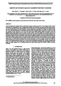
2. PHOTOGRAMMETRY INSTRUMENTS USED IN THIS STUDY 2.1 Inertial Single Photogrammetry Instrument The instrument is shown in Figure.1. The instrument is set in a back pack type carrier so that the tracer can be pursued and photographed even in a place where we are obliged to pay attention to our footholds. As shown in Figure.1, the instrument consists of a shooting device (inertial camera) equipped with a camera and an inertial measurement unit (IMU) and a controller equipped with a battery and a personal computer. An eyepiece attachment is set on the camera to make it easy to pursue the tracer, enabling us to look through the viewfinder from above. The camera is a single-lens reflex digital camera Canon EOS1Ds Mark2 DIGITAL (nominal picture distance: 35 mm; screen size: 36 mm x 24 mm; valid pixels: approx. 16.7 million pixels; total pixels: 17.2 million pixels). IMU is TA7431 made by Tamagawa Seiki Co., Ltd. The angular velocity sensor is a monolithic ring laser gyro T-16B made by Kearfott Corporation, an American manufacturer and with a bias of +0.3 deg/h. The accelerometer is a high-accuracy accelerometer QA-1200 made by AlliedSignal Inc., an American manufacturer and with a bias of +300 microG. The shutter is operated manually but the IMU displays the signal of shutter and is synchronized with the camera.
27
International Archives of the Photogrammetry, Remote Sensing and Spatial Information Sciences, Volume XXXIX-B5, 2012 XXII ISPRS Congress, 25 August – 01 September 2012, Melbourne, Australia
2.2
3. TRACER
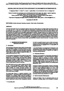
Inertial stereo Photogrammetry Instrument
In this study, an instrument is modified to enable stereo photogrammetry using two cameras, in addition to inertial single photogrammetry, as shown in Figure.2. The camera base length is fixed at 1.2 m, taking into account the operability. The camera is a single-lens reflex digital camera Canon EOS-40D (screen size: 22.2 mm x 14.8 mm; valid pixels: approx. 10.1 million pixels; total pixels: 10.5 million pixels) whose shutter automatically clicks in a continuous way after power-on via a radio controller (proportional system), enabling sequence photography with intervals of 0.33 seconds. This system allows selection between manual single-photograph and automatic stereo-photograph. 2.3
3.1
Spherical rubber balloon
A spherical rubber balloon, which is used as meteorological balloon, was adopted as tracer and was filled with mixture of helium gas and air to be the same weight as the air. Its diameter is fixed to 40 cm because this diameter ensures operability and allows identification even 50 m away from the camera. Figure.4 shows the balloon used. 3.2
Soap Bubbles
Unlike balloons, soap bubbles can be released in large quantity within a short duration, so we can expect they allows more detailed observation of wind flow than balloons. The purpose of this study is to develop a soap bubble generator that can continuously release bubbles of a diameter of 40 cm. At this stage, the best mixture of soap solution is composed of water, granulated sugar, starch and dishwasher detergent in a ratio of 10:10:5:1 by weight. Figure.5 shows the soap bubble generator.
Theodolite Camera
This study adopted a theodolite camera, theodolite equipped with a digital camera, in order to allow calculating the shooting positions and camera inclination, which are exterior orientation parameters. The camera used is the same as that used for the inertial stereo photogrammetry instrument. Four instruments were prepared and all of them are synchronized by radio control to enable sequence photography. The theodolite measures angles with an accuracy of 20 seconds, which allows the photogrammetry requiring no control point. Figure.3 shows the theodolite camera.
40cm
Figure 4. Spherical Rubber Balloon
51cm 61cm Figure 1. Inertial single photogrammetry instrument 63cm
Figure 5. Soap Bubble Generator 4. EXPERIMENT OF OBSERVATION ACCURACY The purpose of experiment is to verify the observation accuracy of the inertial single photogrammetry instrument, inertial stereo photogrammetry instrument and theodolite cameras described in Chapter 2.
Figure 2. Inertial stereo photogrammetry
4.1
Test Method
The experiment was carried out in an open park. Figure.6 shows a view of experiment. A tricycle loaded with a VRS-GPS and a tracer (balloon) ran at a speed of about 5 m/s and was photographed by the inertial single photogrammetry instrument, inertial stereo photogrammetry instrument and theodolite cameras. The photographs thus taken were used for analysis to calculate the three-dimensional position of the tracer and to draw its trajectory. Additionally, the position data were obtained also by VRS-GPS on the tricycle and used for calculating the tracer's trajectory. The position data obtained by
Figure 3. Theodolite camera
28
International Archives of the Photogrammetry, Remote Sensing and Spatial Information Sciences, Volume XXXIX-B5, 2012 XXII ISPRS Congress, 25 August – 01 September 2012, Melbourne, Australia
VRS-GPS were treated as true values, which were compared with the results of observation methods to verify the accuracy. It should be noted that VRS-GPS and other observation methods were synchronized by manually pressing switches so they were not deemed as being precisely synchronized.
5. EXPERIMENT OF OBSERVATION OF WIND FLOWS AROUND EMBANKMENT Paths of particle of winds that flow around embankment were measured in a three-dimensional way. 5.1
The experiment was carried out on a seaside embankment. In this experiment, a soap bubble generator was placed on a tetrapod and bubbles were released from it to make use of winds flowing from the sea to the embankment. A balloon was also released from the same position as the soap bubble generator. The released tracers were photographed by the inertial single photogrammetry instrument, inertial stereo photogrammetry instrument and theodolite camera. The photographs thus taken were used for analysis to calculate the three-dimensional position of the tracers and to draw their paths of particle. Figure.8 shows the view of experiment.
X
Z Figure 6. View of Experiment 4.2
Result of Experiment
The accuracy was verified by comparing the drawn trajectories. Among the trajectories obtained by each method, one whose measurement time is the closest to that of VRS-GPS was adopted. It is because the synchronization is not precise. Figure.7 shows the result of experiment. According to this experiment, each method turned out to be able to provide a trajectory almost equal to one of VRS-GPS. Figure.7 proves that the data from about 65 m deviate. This deviation is considered to have occurred because the balloon's apparent size became smaller on photos. From this result, the analysis range of the inertial single photogrammetry instrument with a balloon of a diameter of 40 cm seems to be about 65 m from the shooting position.
Figure 8. View of Experiment 5.2
40.22秒 ‐7.000 39.50秒 40.23秒
39.89秒 39.55秒 39.18秒
‐5.000
39.83秒
Z
39.55秒
Le gend
39.22 秒 38.88 秒 39.53秒 39.22秒
‐4.000
GPS Theodolite
39.23秒
‐3.000
‐2.000 0.000
Result of Experiment
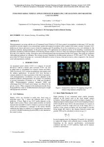
Figure. 9 and 10 show the results of experiment obtained by each of observation methods with released tracers. The red path of particle shows the trajectory of balloon and the blue one shows that of a soap bubble. These figures enable clearly understanding how winds flowing over the embankment go upward above it and go downward behind it. An anemoscope and an anemometer installed there show that the wind was blown from about south (S) at a speed of about 3.46 m/s, which is almost same as analyzed from the photographs.
‐8.000
‐6.000
Experiment Method
Inertial single Inertial stereo
1.000
2.000
3.000
4.000
5.000
6.000
7.000
8.000 [m]
X (a) Displacement experiment in proximity ‐90 ‐80 ‐70 ‐60
Figure 9. Paths of particle obtained by the Inertial single photogrammetry
‐50 ‐40
Z
‐30 ‐20
Le gend
‐10 0 10
GPS Shooting position
Inertil single
20 0
20
40
60
X
80
100
120 [m]
(b) Dsiplacement experiment with a long distance Figure 10. Paths of particle obtained by the Inertial stereo photogrammetry
Figure 7. Comparison between trajectories
29
International Archives of the Photogrammetry, Remote Sensing and Spatial Information Sciences, Volume XXXIX-B5, 2012 XXII ISPRS Congress, 25 August – 01 September 2012, Melbourne, Australia
6. EXPERIMENT OF OBSERVATION OF CONICAL VORTEX AT A CORNER OF BUILDING
7. EXPERIMENT OF OBSERVATION OF WIND FLOWS AROUND A HIGH BUILDING
The purpose of this experiment is to observe conical vortexes generated at a corner of building in a three-dimensional way.
The purpose of this experiment is to observe winds flowing around a high building in a three-dimensional way.
6.1
7.1
Experiment Method
Experiment Method
The experiment was carried out on the roof floor of a 9-story reinforced concrete building. It was intended for observing conical vortexes generated by winds hitting the corner of a building. Figure.11 shows the appearance of the building. Four theodolite cameras were installed at intervals that enable stereo photography and a soap bubble generator was set on the windward side. The photos thus taken were subjected to photogrammetry to calculate the three-dimensional position of bubbles and to draw their paths of particle.
The experiment took a 20-story reinforced concrete building as object. Figure.13 shows the view of experiment. In order to see the wind flows around the high building, tracers were released from the 9th floor level of the outside staircase of a 10-story building situated on the windward side. Tracers released from windward were photographed by the inertial single photogrammetry instrument. The photos thus taken were subjected to analysis to calculate the three-dimensional position of tracers and to draw their paths of particle.
6.2
7.2
Result of Experiment
Result of Experiment
Figure.14 shows the result of experiment obtained by an inertial single photography camera with released balloons. This result enables understanding that winds flow around the high building as if they avoid its higher part.
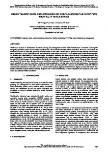
Figure.12 shows the paths of particle obtained from the experiment. These lines clearly prove that conical vortexes were generated by winds hitting the corner of edge of eaves of the roof floor on the windward side. It was also planned to carry out observation by the inertial single photogrammetry instrument and intertial stereo photogrammetry instrument, but the analysis was given up because too large number of bubbles and their too complicated move made stereo-matching impossible. It turned out that observation by theodolite cameras allowing sequence photography is useful for a situation like this experiment where the wind flows in a complicated way.
Figure 13. View of experiment Corner of builging
Figure 11. Outer view of building where the observation was carried out Legend ― ― ― ― ― ― ― ―
No.1 No.2 No.3 No.4 No.5 No.6 No.7 No.8
Figure 14. Paths of particle around the high building Main wind direction
C o rner building
8. CONCLUSION (1) We prepared soap bubbles useful as tracers in wind observation by photogrammetry and a soap bubble generator. (2) We developed an inertial single photogrammetry instrument and an inertial stereo photogrammetry instrument as new observation methods. (3) We summarized the advantages and disadvantages of these observation methods. (4) With their commercial use in view, we observed wind flows around an embankment, conical vortex at a corner of building and wind flows around a high building according to these
Sope bubble generator
Figure 12. Paths of particle of conical vortex at a corner of building
30
International Archives of the Photogrammetry, Remote Sensing and Spatial Information Sciences, Volume XXXIX-B5, 2012 XXII ISPRS Congress, 25 August – 01 September 2012, Melbourne, Australia
methods. As presented in this study as applications, the instruments were proved to be useful for wind observation. References: Koizumi, T., 2010. Development of wind observation system utilizing inertial single photogrammetry, Journal of the Japan Society of Photogrammetry and Remote Sensing, Vol.49, No.1, pp.21-31. Koizumi, T., et. al., 2011. Development of a wind observation system utilizing simplified aerial photogrammetry (3) -The measurement of wind flow by phototheodolite and soap bubbles-, Journal of Wind Engineering, JAWE, Vol.36, No.1 (No.126), pp.1-12.
31