4th IEEE Conference on Automation Science and Engineering Key Bridge Marriott, Washington DC, USA August 23-26, 2008
Development of Flexible Laboratory Automation Platform using Mobile Agents in the Clinical Laboratory Byung June Choi1 , Sung Moon Jin1 , Seung Hoon Shin1 , Ja Choon Koo1 , Sung Moo Ryew2, Min Cheol Kim3 , JinHyun Kim4 , Woong Hee Son5 , Ki Tak Ahn6 , Wankyun Chung7 and Hyouk Ryeol Choi∗1
Abstract— Recently, robotic automation in clinical laboratory becomes of keen interest as a fusion of bio and robotic technology. In this paper, we present a new robotic platform for clinical tests suitable for small or medium sized laboratories using mobile robots. The mobile robot called Mobile Agent is designed as transfer system of blood samples, reagents, microplates, and other instruments. Also, the mobile agent can perform diverse tests simultaneously based on its cooperative and distributed ability. The driving circuits for the mobile agent are embedded in the robot, and each mobile agent communicates with other agents by using Bluetooth communication. The RFID system is used to recognize patient information. The BioRobot platform based on mobile agents can control throughput according to the amount of tests. Also, the operation and maintenance of the system can be improved because its components are easily replaceable. To evaluate feasibility for BioRobot platform, the system was manufactured and validated by preliminary experiments.
I. INTRODUCTION Recently, automated machines have been used to carry out most of the laboratory works, so the need for robotic automation in the clinical laboratory has been growing rapidly. However, the Total Laboratory Automation(TLA) system to be used in large hospitals has been optimized by adopting the conveyer belt method for rapid inspect of a large number of samples. The conveyer belt system is difficult to setup in small or medium sized hospitals since the size of system is enormous, and large amount of investment is needed to introduce related facilities. Therefore, when
small or medium sized hospitals carry out clinical tests, they should process manual operation, or send the samples to dedicated facilities for testing. In order to realize the ordered medical diagnosis for patients, the new concept of clinical laboratory system is required to support high flexibility and personalization. The robotic technology for clinical testing related to miniaturization, modularization and intelligence can be proposed to the collective and distributed approaches using small mobile robots [1]- [6]. Up to now, many researches on analytical techniques or innovative analytical devices have been reported [1][21]. Also, personalized clinical test with modular robotic automation appears to be attractive as an alternative to the TLA system [7]. Robotic automation is defined as a dedicated robotic system capable of performing selective laboratory tasks. In general, robotic automation is flexible and requires less footprint and financial investment than the TLA system. Shortcoming of throughput compared to TLA is compensated with flexibility of operation under minimum overhead. Robotic automation systems designed for selective analytical tasks may better meet the needs of small- or medium-sized laboratories because these systems can either operate stand alone, or integrated to form work cells [8]- [11]. Also, the robotic system can be customized or personalized based on the needs and budget of individual laboratory [12]- [14].
This work was supported by “Development of Intelligent Robot Technologies for Laboratory Medicine by Applying Biotechnology” under the Development of Next-Generation New Technology program (100247152005-11) of the Korean Ministry of Commerce, Industry and Energy. H. R. Choi is with Professor of School of Mechanical Engineering, Sungkyunkwan University, Suwon, The Republic of Korea.
[email protected] S. M. Ryew is with Director of KnR System Inc., Youngin, The Republic of Korea.
[email protected] M. C. Kim is with Director of Robotous Co, Seongnam, The Republic of Korea.
[email protected] J. H. Kim is with Professor of Department of Mechanical Engineering, Seoul National University of Technology, Seoul, The Republic of Korea.
[email protected] W. H. Son is with Chief Researcher of Division of Applied Robot Technology, Korea Institute of Industrial Technology, Cheonan, The Republic of Korea.
[email protected] K. T. Ahn is with Researcher of Pohang Institute of Intelligent Robotics, Pohang, The Republic of Korea.
[email protected] W. K. Chung is with Professor of Department of Mechanical Engineering, Pohang University of Science and Technology, Pohang, The Republic of Korea.
[email protected]
978-1-4244-2023-0/08/$25.00 ©2008 IEEE.
Fig. 1. Concept of BioRobot platform using new transfer system called Mobile Agent
In this paper, the flexible laboratory automation using small mobile robots is proposed that can be used as various analyses for laboratory automation, including immunoassay analysis, serological tests, chemistry tests, peripheral blood
918
Authorized licensed use limited to: IEEE Xplore. Downloaded on February 10, 2009 at 21:01 from IEEE Xplore. Restrictions apply.
TABLE I S PECIFICATION OF B IO ROBOT P LATFORM Hardware components
Robot arm Sample tray Reagent tray Expected throughput Dimension(W×D×H)
2×Microplate loading module, 8×Recharging and docking module, 1×SCARA robot, 1×Dispensing channel, 1×Sample tray, 1×Reagent tray, 1×Incubator, 4×Spectrophotometer, Mobile Agents 4-DOF SCARA type 7mL tubes, 21 samples 40mL tubes, 72 samples 240 photometric tests/hour 1560×1100×1200(mm) (from the ground to the base plate (workspace of Mobile Agents))
tests, and blood transfusion tests, etc. The robotic platform consists of mobile robots, sample tray, supply parts for pipettes and microplates, robotic manipulator, reagent chamber module, incubator module, photometry scanner, etc. These mobile robots can be used in a determined space as a transfer system of blood samples, reagents, microplates, and any instruments. Our clinical laboratory system using mobile robot is referred to as the “BioRobot platform”, and mobile robot of the BioRobot platform is called the “Mobile Agent”. The BioRobot platform can be incorporated with various modules for pre- or postanalytical processing in the clinical tests [15]. This paper is organized as follows. In sections II and III, the motivation and design of BioRobot platform are presented. Also, the design of mobile agent system is described in section IV. In section V, schematic of controller for the BioRobot platform is presented. In section VI, experimental procedures for evaluation of the performance of the mobile agent are mentioned. Finally the paper is concluded with summary in section VII. II. MOTIVATION: NEW TRANSFER SYSTEM FOR CLINICAL TEST
Fig. 2.
System design of BioRobot platform for laboratory automation
Personalization, miniaturization and modularization in clinical test may open a new frontier in medical business such as remote medical care etc. The personalized robot system has advantages with respect to flexibility, maintenance cost, and investment, etc., though it cannot compete with the TLA in terms of throughput [12]- [16]. In addition, transport functions and post-analytical processors embedded in the system can guarantee convenience and efficiency of the clinical test. However, current clinical laboratories do not appear to have successfully incorporated robot technology in reality, though great progresses have been achieved in the robotics. In a general clinical laboratory system with optimized high-throughput, the blood sample is transported via a conveyer belt, and in one with optimized flexibility and diversity, the blood sample is transported via a robot arm. However, instrument using conveyer belt is difficult to deal with flexibility, and instrument using the robot arm is difficult to deal with high-throughput. Also, in the case of a conveyer belt system or robot arm, if the transporting system is in trouble, the entire system must be halted. In this paper, the new intelligent transfer system for clinical laboratory is proposed and developed, as shown in Fig. 1. The developed mobile agents can transport blood samples, and can perform various tests simultaneously. Also, it is controllable throughput according to amount of tests. Even in the event of an abnormal operation in any part of the robot system, the entire system can function very well without problems. It can minimize the transporting distance as being included in many clinical tests. III. D ESIGN OF B IO ROBOT P LATFORM As depicted in Fig. 2, a new BioRobot system for clinical tests should be considered to support near-patient testing in the small and medium sized hospitals or laboratories. It provides sufficient functions prerequisite in clinical diagnosis such as analytical methods of about 70 clinical tests. The BioRobot platform is composed of mobile agents, SCARA robot for handling samples and reagents, elevator module to supply microplates on the mobile agents, sample tray module(21 test tubes, each sample tube has an exclusive pipette tip to prevent the mixture of samples and reagents at the aspirating and aliquoting process), reagent chamber module(72 test tubes, each reagent tube has an exclusive pipette tip to prevent the mixture of samples and reagents at the aspirating and aliquoting process), incubator module, and photometry scanner. The basic functions of the proposed BioRobot platform are enlisted as loading of the sample and reagent, identification of sample, test planning, dispensing of the sample and reagent, transfer, incubation, and detection. First, the samples and reagents are loaded into individual tubes. Then, the samples and reagents are identified at each tray by using the RFID system. The user determines the test sequences using the provided scheduler software. Now, the BioRobot platform is automatically operated according to the job schedules. The microplate is loaded on the mobile agent
919 Authorized licensed use limited to: IEEE Xplore. Downloaded on February 10, 2009 at 21:01 from IEEE Xplore. Restrictions apply.
Microplate
using microplate loading module. After the mobile agent transfers the microplate from loading module to SCARA robot, it holds the microplate and waits until the dispensing task finishes. Next, the liquid handler combined with the pipette tip absorbs the samples or reagents from the each of the sample or reagent tubes, and each sample or reagent is dispensed to the well of the microplate. Then, the mobile agent with the microplate containing mixtures of the sample and the reagents is moved to the incubator module. The results of tests are read with a spectrophotometer. Finally, the mobile agent with the microplate returns to its initial position(microplate loading module). These functions can reduce the clinical test procedure. According to the integrated clinical test detector on the mobile agent, inspection is performed simultaneously. The clinical test process is changed from sequential procedure to parallel procedure. The efficiency and speed of a test are optimized. The clinical test system can be treated flexibly in the every clinical test method. Also, even if one of the mobile agents breaks down, the entire system remains unaffected. Lastly, the operation and maintenance of the system can be improved because its components are easily, replaceable.
Clinical Module
Mobile module Fig. 4.
Mobile agent for clinical test
Microplate RFID tag
Detector board for clinical test RFID antenna
Interface board
IV. DESIGN OF MOBILE AGENT SYSTEM Fig. 5.
Fig. 3.
System schematic of Mobile agent
To carry out clinical tests, mobile agents for laboratory automation were developed. The mobile agent is designed to integrate with the equipment based on small, modular systems, and to transport the reagents and blood samples for economical efficiency. As shown in Fig. 3, the proposed mobile agents system for BioRobot platform is composed of clinical test module, mobile module and stage module. The overview of BioRobot platform is shown in Fig. 4. A. Clinical Test Module The clinical test module of a mobile agent is used to perform various clinical tests such as the recognition of patient information and detection and inspection of blood samples, and so on. The proposed clinical test module is composed of a microplate, RFID tag and reader, and
Clinical module
interface board. The overview of the BioRobot platform is shown in Fig. 5. The size of the clinical module is 39.5 x 23.5(mm). The new microplate with 24 wells of 10 µ L in volume is designed and adapted to fit into the concept of miniaturization and throughput of small or medium sized hospitals. Also, an RFID tag is attached in the microplate. The patient information is previously registered in the RFID tag. Therefore, the microplate with the RFID tag prevents recognition error of as the mobile agent performs clinical tests. An RFID antenna is located under the microplate, it satisfies the recognition range of RFID tag (less than 30mm). The interface board of the clinical test module can be easily integrated with additional functions or devices of a clinical test. B. Mobile Module The mobile module of the BioRobot Platform, which can move on the stage and can communicate with the PC, is a small sized mobile robot of differential driving type for silent and stable traveling. As shown in Fig. 6, the mobile module is cylindrical of 118mm in diameter and 90mm in height. Also, it also weighs about 603g. The mobile agent uses two 2W DC motors and gears with 17:4 ratio. Two ball casters were used to prevent the inclined appearance. The mobile agent was designed to have 1m/s2 acceleration, and 1m/s velocity. The mobile module equipped the lithiumion battery can move independently, and can move about 60 minutes without recharging. Also, the electrical pads for recharge are exposed on the outside of the robot for
920 Authorized licensed use limited to: IEEE Xplore. Downloaded on February 10, 2009 at 21:01 from IEEE Xplore. Restrictions apply.
the locomotion of the mobile agent [18]- [21]. However, because the system needs precise position information for a clinical laboratory test, position error should be removed to implement the BioRobot system successfully. Therefore, we designed a stage module installed with permanent magnets to compensate the accumulated position error, as shown in Fig. 7. Therefore, the mobile agent can correct the error during the locomotion, and can reach one’s goal position accurately. Stage module for preliminary tests is composed of twelve stage boards. As shown in Fig. 7, the size of each board is 300 × 200 × 12(mm). Four permanent magnets are located in the center of the stage board, and position information is recognized by the magnetic hall sensor of the mobile module, which reads the magnetic field. When a mobile agent is situated on the permanent magnets, the magnetic hall sensor measures the position difference between coordinates of the mobile agent and coordination of magnets. Then, the output voltage is calculated in the DSP microprocessor, and is transmitted to the PC through Bluetooth communication. The position information is shown in the GUI in the PC according to previously measured relation of the output voltage and position of the mobile agent.
Recharging Connector Battery
Bluetooth Module
DSP Microprocessor
Motor & Encoder Motor & Encoder
Magentic Hall Sensor
Fig. 6.
Mobile module
TABLE II S PECIFICATION OF MOBILE MODULE Size (Radius × Height)[mm] Weight [kg] Microprocessor Actuator Sensor Power supply Communication
118 × 90 0.603 TMS320F2811 2 DC motors (17:4 gear ratio) Encoders, Magnetic Hall sensor 7.4V, 1020mAh, Lithium-Polymer rechargeable Bluetooth communication
automatic charging. The magnetic hall sensor is installed to remove and compensate the accumulated error of locomotion at the bottom of the mobile agent, which is the weak point of a mobile robot of differential driving type. Also, the position of a mobile module is initialized precisely by gripping the mobile module using the gripper of the docking module. All information is transmitted from the mobile agent to the PC via bluetooth communication. The mobile agent can control and communicate with the PC via the bluetooth communication method. Motors are controlled by the main microprocessor of mobile modules that is used TMS320F2811. Motor controllers control the two DC motor using PID control. States of the system can be monitored in the main controller by using the output signals of encoders, and magnetic hall sensors, and then, the feedback parameters are sent to the main controller. C. Stage Module
800 mm
Permanent Magnets
900 mm
Fig. 7.
Stage module
The mobile agents move on the BioRobot platform. The accumulated position error characteristically occurs from
Fig. 8.
Rechargeable docking module
As the other method for compensating the position, we propose a method that can adjust the position error. This method can be realized by arranging the automatic charging docking module with the gripper at the initial point or target point. Consequently, unless the stage module installed with a permanent magnet to remove the accumulated position error, the docking module was designed to provide absolute and precise position information by gripping mobile agent using the gripper in the area that is need precise posture, as shown in Fig. 8. Also, the docking module was designed to embed the charging circuit and device, and it can charge the mobile agents through electrical connectors that are exposed on the outside of the docking module. V. C ONTROLLER As shown in Fig. 9, the BioRobot platform is controlled by motion controllers that can provide the processing power, system stability, management capability, and real-time performance for low-level control of individual hardware devices such as motors and pneumatic actuators, and so on. Software with a scheduler interfaces with the hardware, while communicating with a personal computer for the user interface. The computer performs general control tasks for analyzers, providing support for a range of operating systems, development and user-interface tools, data management options, and interfaces for communication.
921 Authorized licensed use limited to: IEEE Xplore. Downloaded on February 10, 2009 at 21:01 from IEEE Xplore. Restrictions apply.
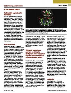
The cumulative error of x-axis Difference between real displacement without compensation and desired displacement Difference between real displacement with compensation and desired displacement
Error of x-axis displacement [mm]
50 45 40 35 30 25 20 15 10 5 0 300
600
900
1200
1500
Experiment Point [mm]
Fig. 11.
Fig. 9.
The cumulative error of x-axis displacement
The cumulative error of rotation
Schematic of control system
Difference between real angle without compensation and desired angle Difference between real angle with compensation and desired angle
2 0
BioRobot platform is fabricating for optimization of the module hardware, interfaces, and software. In this section, the mobile agent system for BioRobot platform was tested preliminarily with recognition of microplate of clinical test module, position estimation of mobile agents, and performance of the BioRobot platform for clinical test. It is important that the BioRobot system recognizes the microplates by means of clinical laboratory system. While a microplate is loaded in the clinical test module, the data about the microplate are transmitted to the mobile module every 200ms and transmitted via bluetooth communication packet. The Bluetooth communication packet is transmitted to the PC, and the user can manage the information such as what kind of microplate does the clinical module load, and which microplate is removed or changed, and so on. In the experiments, the three microplates were recognized after installing on the clinical modules. It is possible to confirm that the developed clinical module can detect the a specified microplate. The cumulative error of y-axis Difference between real displacement without compensation and desired displacement Difference between real displacement with compensation and desired displacement
Error of y-axis displacement [mm]
10 5 0 -5
300
600
900
1200
1500
-10 -15 -20 -25 -30 -35 -40 Experiment Point [mm]
Fig. 10.
The cumulative error of y-axis displacement
As mentioned above, the mobile agent generates odometric error because of the diameter tolerance of wheel, misalignment of the wheels, slipping, nonplanar surface,
Error from the real angle [Deg]
VI. EXPERIMENTS
-2
60
120
180
240
300
360
-4 -6 -8 -10 -12 -14 -16 -18 Desired angle [Deg]
Fig. 12.
The cumulative error of rotation
etc. More critical problems related to such error are continuously accumulated, and as a result, mobile agents can be moved away to an unexpected position and not to the target position. Therefore, to remove such position error, the mobile agent compensates the error by using stage installed with a permanent magnet. In the second experiments, the mobile agent installed with laser pointer was moved along the determined trajectory, and the indications of laser pointer were obtained when mobile agents came back to its initial point and target point. The determined trajectories with the displacement between 300mm and 1500mm were repeated about each displacement during 80 times, and the errors of y-axis and x-axis were obtained and averaged as shown in Figs. 10 and 11. Also, the error of rotation value θ was observed for each specific angle, as depicted in Fig. 12. Figs. 10, 11, and 12 show the results of measurement of the difference between the position error without compensation and that with compensation using magnets. From the experiments results, it was possible to confirm that the position error was continuously accumulated in the mobile agents with no compensation of the position information. Also, it is concluded that the mobile agent using the magnetic Hall sensor can estimate and compensate cumulative errors effectively. Also, the docking module could perform the task of initialization to provide absolute and precise position by gripping the mobile agent using the gripper. Finally, the overall mobile agent system was tested by
922 Authorized licensed use limited to: IEEE Xplore. Downloaded on February 10, 2009 at 21:01 from IEEE Xplore. Restrictions apply.
R EFERENCES
Fig. 13.
Movement of Mobile agents
reproducing a clinical test. We confirmed all information through the user interface on the PC. First, the microplates were loaded into individual mobile agents. Then, samples and reagents were identified at each tray by using an RFID system. Mobile agents were moved to the liquid module, and then, each sample or reagent was dispensed to the well of the microplate on the mobile agent. Then, the microplate containing mixtures of the sample and the reagents was transferred to the incubator module, and the results of tests were read with a spectrophotometer. Finally, the mobile agent returned to the initial position. According to the experiments, mobile agents can move to the target position precisely, and can perform the required task by means of distributed robotic system, as shown in Fig. 13. Therefore, it is possible to confirm that the mobile agent can be used in various applications as well as clinical tests. VII. CONCLUSIONS In this research, we proposed a new robotic platform for clinical tests suitable for small or medium sized laboratories using mobile robots. Different from the previous small mobile robots, a mobile agent was designed to carry out the clinical tests and attached with a special sensor to be used the clinical tests. BioRobot platform based on mobile agents can control throughput according to amount of tests. Also, the operation and maintenance of the system can be improved because its components are easily replaceable. To evaluate possibility for applying to the BioRobot platform, the mobile agent system was validated through preliminary experiments. As on going research, the entire BioRobot platform will be built for autonomous operation. Also, reliability of the system on the real circumstances will be carried, and as the results, further improvements should be accompanied in terms of optimization of the module hardware, interfaces, and software. Finally, we will control the mobile agent for clinical tests by using the complete BioRobot system, and evaluation will be performed.
[1] M. Sasaki, T. Kageoka, K. Ogura, H. Kataoka, T. Ueta, S. Sugihara, “Total laboratory automation in Japan past, present and the future”, Clinica Chimica Acta, vol. 278, 1998, pp. 217-227. [2] J. C. Boyd, R. A. Felder, J. Savory, “Robotics and the changing face of the clinical laboratory”, Clinical Chemistry, vol. 42, 1996, pp. 19011910. [3] J. W. Holman, T. E. Mifflin, R. A. Felder, L. M. Demers, “Evaluation of an Automated Preanalytical Robotic Workstation at Two Academic Health Centers”, Clinical Chemistry, vol. 48, no. 3, 2002, pp. 540-548. [4] S. Bauer, C. Teplitz, “Total lab automation: system design”, Medical Laboratory Observer, vol. 27, 1995, pp. 44-50. [5] S. Bauer, C. Teplitz, “Total laboratory automation: a view of the 21st century”, Medical Laboratory Observer, vol. 27, 1995, pp. 22-25. [6] J. Zakowski, D. Powell, “The Future of Automation in Clinical Laboratories”, IVD Technology Magazine, July 1999, pp. 48-59. [7] R. A. Felder, G. J. Kost, “Modular Stepwise Automation”, Medical Laboratory Observer, vol. 30, 1998,pp. 22-27. [8] S. Graves, B. Holman, R. A. Felder, “Modular Robotic Workcell for Coagulation Analysis”, Clinical Chemistry, vol. 45, no. 5, 2000, pp. 772-777. [9] R. A. Felder, G. J. Kost, “Modular Stepwise Automation and the Future of Diagnostic Testing”, Medical Laboratory Observer, vol. 30, 1998, pp. 46-56. [10] R. A. Felder, “Modular workcells: modern methods for laboratory automation”, Clinica Chimica Acta, vol. 278, 1998, pp. 257-267. [11] S. Graves, H. Holman, M. Rossetti, C. Estey, R. A. Felder, “Robotic automation of coagulation analysis”, Clinica Chimica Acta, vol. 278, 1998, pp. 269-279. [12] J. Boyd, “Robotic Laboratory Automation”, Science, Washington, D. C.,vol. 295m, 2002, pp. 517-518. [13] R. Petersen, M. G. Bissell, “Leveling the playing field: the economics of robotics in the hospital clinical lab”, Medical Laboratory Observer, vol. 30, 1998,pp. 42-45. [14] D. R. Meldrum, C. H. Fisher, M. P. Moore, M. Saini, M. R. Holl, W. H. Pence, S. E. Moody, D. L. Cunningham, P. J. Wiktor, “ACAPELLA5K, A High-Throughput Automated Genome and Chemical Analysis System”, Intl, Conference on Intelligent Robots and Systems, 2003, pp. 2321-2328. [15] B. J. Choi, S. M. Jin, S. H. Shin, J. C. Koo, S. M. Ryew, J. H. Kim, W. H. Son, K. T. Ahn, W. K. Chung, H. R. Choi, “Development of Flexible BioRobot Platform for Integrated Clinical Test”, Journal of the Association for Laboratory Automation, 2008, vol. 13, no. 2, pp. 90-96. [16] M. G Bissell, J. R. Petersen, “Automated integration of clinical laboratories: A reference”, AACC press (Washington, D. C.), 1998, pp. 60-97. [17] R. Schafer, “Concepts for Dynamic Scheduling in the Laboratory”, Journal of the Association for Laboratory Automation, vol. 9, no. 6, 2004, pp. 382-397. [18] F. Mondada, E. Franzi, and P. Ienne, “Mobile Robot Miniaturization: A Tool for Investigation in Control Algorithm”, Proceedings of the Third International Symposium on Experimental Robotics, Springer Verlag, 1993, pp. 501-513. [19] D. J. Stilwell and J. S. Bay, “Toward the Development of a Material Transport System using Swarms of Ant-like Robots”, Proceedings of International Conference on Robotics and Automation, 1993, pp. 756761. [20] R. Gro, M. Bonani, F. Mondada, M. Dorigo, “Autonomous SelfAssembly in Swarm-Bots”, IEEE Transactions on Robotics, vol. 22, no. 6, 2006, pp. 1115-1130. [21] R. Siegwart and I. R. Nourbakhsh, Introduction to Autonomous Mobile Robots, MIT Press, Cambridge, Massachusetts; 2004.
VIII. ACKNOWLEDGMENTS This work was supported by “Development of Intelligent Robot Technologies for Laboratory Medicine by Applying Biotechnology” under the Development of Next-Generation New Technology program (10024715-2005-11) of the Korean Ministry of Commerce, Industry and Energy.
923 Authorized licensed use limited to: IEEE Xplore. Downloaded on February 10, 2009 at 21:01 from IEEE Xplore. Restrictions apply.